1
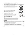
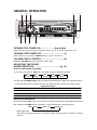
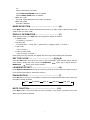
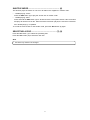
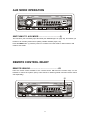
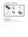
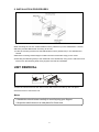
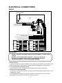
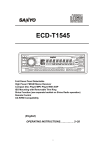
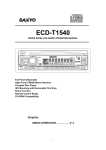
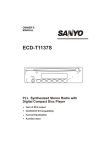
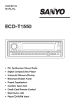
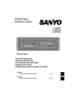
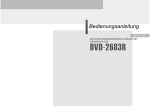
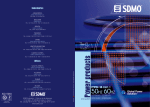
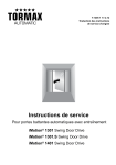
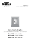
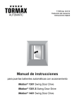
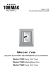
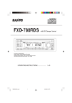
ECD-T1540
SIRIUS SATELLITE RADIO OPERATING MANUAL
VOLUME
45W x 4
MANU/SKIP
S-MOD
SAT
CAT
LOUD/
ENTER
P.SCAN
Full Panel Detachable
High Power FM/AM Stereo Receiver
Compact Disc Player
ISO Mounting with Removable Trim Ring
Sirius Function
Remote Control Ready
CD-R/RW Compatibility
(English)
SIRIUS OPERATION……………. 2~3
1
SIRIUS OPERATION
3
5
VOLUME
45W x 4
MANU/SKIP
S-MOD
SAT
CAT
LOUD/
ENTER
P.SCAN
2
4
8
6
7
1
SWITCHING TO SIRIUS MODE……………………..…(1)
Press MOD button (1) to select Sirius mode.
SELECTING USER-PRESET CHANNEL……………..(2)
At Sirius mode, the Sirius user-preset channel group (3 groups) is toggled cyclically through the
group by quickly pressing the BND/LOUD/ENTER button (2).
The channel will change in the following order:
SR1
SR2
SR3
SELECTING CHANNEL UP/DOWN……………………(3)
Press the MANU/SKIP
or
button (3) to select the channel up or down.
SEARCHING STATION…………………………….……(4)
When the AS/PS/P.SCAN button (4) is pressed, the channel searches for each user preset
station from SR1 to SR2 to SR3.
When an available channel is detected, the station will be held at that preset number and play for
5 seconds. After that, it will mute and search for another available station
STORING PRESET STATIONS .................................(8)
The preset buttons (8) can be used to store 6 stations for convenient access to your favorite
stations.
• Programming stations ..... 1. Select the desired station you want to store in memory.
2. Press and hold one of the preset buttons (8) for more than 2
seconds until the corresponding preset button number appears.
Repeat steps 1. and 2. to program additional stations.
• Quick tuning .................... Press one of the six preset buttons 8 shortly to select a preset
station directly.
2
SIRIUS MODE SELECTION ...........................…..(5)
Press LOC/S-MOD button (5) to switch Category mode, Skip mode or normal. It is used as the
selection of each:
Normal
Category mode
Direct Tune
Skip Channel mode
When Category mode or Skip mode is engaged, the “CATEGORY” or “SKIP” function is turned
on in the display. When Category mode or Skip mode is released, the “CATEGORY” or “SKIP”
function is turned off. When Direct mode is engaged, “DIRECT” of alphanumeric display is turned
on.
Select Category and TUNE UP/DOWN within selected Category
Use CAT
button (7) or
CAT button (6) to select desire Category and press
BND/LOUD/ENTER button (2).
In Category mode, stations can be tuned within the same category.
-
When the user wishes to search by Category, press LOC/S-MOD button (5) can be pressed
until it goes into Category search mode.
button (7) or
CAT button (6) up and down to get to the desired category.
-
Press CAT
-
To change channels, press LOC/S-MOD button (5) again to Normal mode, and then press
MANU/SKIP
or
button (3) to select the channel up or down.
The operation of skip channel function
In Skip mode, pressing LOC/S-MOD button (5) for more than 3 seconds sets the SKIP channel
mode. Details for set or release skip channel is as follows.
Use MANU/SKIP
or
button (3) to be switched to SKIP channel set or release mode
sequentially.
-
Press BND/LOUD/ENTER button (2) to select skip or release the following channel. (If the
channel was skipped, the “SKIP” icon will be displayed.
-
Press LOC/S-MOD button (5) for more than 3 seconds again to return to basic mode
automatically after 10 seconds.
Note:
In skip mode, use MANU/SKIP
or
button (3) to show skipped channels.
How to direct tune
1. In direct mode, display shows DIRECT and “000” channel number. (Hundred Digit flashing
on/off)
2. Use MANU/SKIP
or
button (3) to select hundred digit.
3. Press LOC/S-MOD button (5) again to confirm entry of the hundred digit and the 10s digit is
flashing on/off.
4. Use MANU/SKIP
or
button (3) to select 10s digit.
5. Press LOC/S-MOD button (5) again to confirm entry of the 10s digit and the 1s digit is
flashing on/off.
6. Press LOC/S-MOD button (5) again to confirm entry of the 1s digit.
7. Press BND/LOUD/ENTER button (2) to direct tune.
3
ECD-T1540
VOLUME
45W x 4
MANU/SKIP
S-MOD
SAT
CAT
LOUD/
ENTER
P.SCAN
Full Panel Detachable
High Power FM/AM Stereo Receiver
Compact Disc Player
ISO Mounting with Removable Trim Ring
Sirius Function (see separate booklet on Sirius Radio operation)
Remote Control Ready
CD-R/RW Compatibility
(English)
OPERATING INSTRUCTIONS… … … … … . 2~24
1
CONTENTS
COMPACT DISC CARE .................................................................................................. 3
DIGITAL DISPLAY ........................................................................................................... 4
DETACHABLE FRONT PANEL......................................................................................... 5
GENERAL OPERATION ................................................................................................... 6
RADIO OPERATION ........................................................................................................ 8
CD OPERATION.............................................................................................................. 10
CDC OPERATION............................................................................................................ 12
AUX MODE OPERATION ................................................................................................. 14
REMOTE CONTROL READY ........................................................................................... 14
ERROR SIGNS ................................................................................................................ 15
HINTS FOR PROPER AND SAFE OPERATION ................................................................ 16
TROUBLE SHOOTING ..................................................................................................... 17
ACCESSORIES AND HARDWARE ................................................................................... 18
INSTALLATION................................................................................................................ 18
UNIT REMOVAL .............................................................................................................. 19
ELECTRICAL CONNECTIONS ......................................................................................... 20
LINE OUT CONNECTIONS .............................................................................................. 22
AUXILIARY INPUT CONNECTIONS ................................................................................. 22
CAUTION
• This unit is designed to operate on 12 volts DC, NEGATIVE ground electrical systems only.
• When fuse replacement is necessary, use only a 15 amp fuse. Do not replace with a higher
rated fuse. If the fuse blows often, carefully check all electrical connections for any short
circuits and have your car’s voltage regulator checked also.
• Do not install the unit where it will be exposed to direct sunlight or hot air discharged from the
car heater.
• Do not expose the unit to water or moisture.
• To avoid damaging the unit, never insert anything other than a compact disc into the disc slot.
• This unit should not be adjusted or repaired by anyone except qualified service personnel.
If servicing is required, return the unit to an authorized SANYO mobile audio dealer.
• Use the Controls or adjustments or performance of procedures other than those specified
herein may result in hazardous radiation exposure.
• Changes or modifications not expressly approved by SANYO may void the user’s authority to
operate this equipment.
2
COMPACT DISC CARE
Dirt, dust, scratches and warpage can cause a deterioration in the sound or intermittent skipping
some tracks during play.
TEXT
ReWritable
• This unit has been designed to play compact
discs bearing the identification logo shown on
the left. No other discs can be played.
• Do not use non-conventional discs such as
heart- shaped, octagonal discs, etc.
The player could be damaged.
• Fingerprints and dust should be carefully
wiped off the signal surface of the disc
(glossy side) with a soft cloth.
Wipe in a straight motion from the inside to
the outside of the disc. Unlike conventional
records, the compact disc has no grooves to
collect dust and debris. Small dust particles
will have no effect on reproduction quality.
• Do not insert a disc which is cracked into the
unit.
• Do not apply paper or write anything on the
surface of the disc.
• To prevent warping the disc, do not expose
it to direct sunlight, high humidity or high
temperatures for extended periods of time.
• Never use chemicals such as record cleaning
sprays, antistatic sprays or fluids, benzene
or thinner to clean compact discs.
These chemicals will permanently damage
the plastic surface of the disc.
• When not using the disc player for extended
periods of time, remove the compact disc and
return it to the plastic storage case. This will
protect the disc from dust and exposure to
the sun.
Recommended CD-R/RW Media
Data may not be properly written to CD-R/RW media depending on the quality of the media.
If this happens, the data may not be reproduced correctly. We recommend the following
manufacturers to insure proper quality of the media.
CD-R Media
TDK USA Corp., Taiyo Yuden (U.S.A.), Inc., Ricoh Corporation, Eastman Kodak Company,
Maxell Corporation of America, Mitsubishi Chemical Corporation, Fuji Photo Film U.S.A.,
Inc., Mitsui Chemicals, Inc., Sony Corporation of America, Philips Electronics North
America Corporation, Imation Corp.
CD-RW Media
TDK USA Corp., Ricoh Corporation, Mitsubishi Chemical Corporation.
Additionally, CD-R media compatible with various speeds such as 2X and 1X-4X are
available. Please refer to the instruction manuals of the drive and the recording software
you are using to selection of the correct media.
3
DIGITAL DISPLAY
CD-IN indicator
Radio Frequency, Time, CD
Track Number, Audio Control
Selected Mode
Stereo
Local
SAT
Channel name
indicator
Category
CLASSIC
Mono
SAT
Skip
POP
Artist
Channel name
Loud
ROCK
Song title
4
DETACHABLE FRONT PANEL
The front panel is designed to be removable for antitheft purposes.
It is recommended that you remove and carry the front panel with you when you leave your car.
HOW TO ATTACH THE FRONT PANEL
Align the right side of the panel (A) with the stopper (B), and then
push the left side of the panel into the unit until it clicks.
A
B
HOW TO DETACH THE FRONT PANEL
Press the release button (REL ) to release the front panel.
Pull the entire panel to remove it from the unit.
REL button
RETURNING TO THE INITIAL SETTINGS
When the front panel is detached, you can find the RESET
button on the front side of the unit. Press the button, the
Microcomputer of the unit returns to the initial settings. If
the display window is not properly shown or the unit
malfunctions, press the RESET button.
RESET button
Note
The unit will not operate if panel is installed incorrectly.
CAUTION
•
•
•
•
•
•
•
Do not attempt to remove the panel in a manner other than that described above.
When installing the panel, do not force it into the unit.
Do not touch the connection terminals of the panel or the unit. It may cause poor contact.
Use a clean, dry cloth when cleaning the terminals.
Keep the panel out of direct sunlight and high temperatures.
Prevent the panel from coming into contact with benzene, thinner, or insecticides.
Do not drop the panel.
5
GENERAL OPERATION
5
10
2
8
VOLUME
9
45W x 4
MANU/SKIP
S-MOD
SAT
CAT
LOUD/
ENTER
1
3
6
P.SCAN
7
4
TURNING THE POWER ON........................Any button
Install the front panel and press any button (except
and
button) when ACC is on.
TURNING THE POWER OFF ...............................… .. (1)
When system is on, press the POWER button (1) to turn off the unit.
VOLUME LEVEL CONTROL.......................................(2)
Rotate the VOLUME dial (2) to adjust the volume level.
ADJUSTING THE SOUND
CHARACTERISTICS ..................................… ......(2), (3)
Press the SEL button (3) shortly:
1. Each time you press the SEL button (3) shortly, the item changes as follows;
VOL
BAS
TRE
BAL
FAD
(Volume)
(Bass)
(Treble)
(Balance)
(Fader)
2. Rotate the VOLUME\CH-SEL dial (2) to adjust the selected item. Make the adjustment within
5 seconds after selecting. After 5 seconds, the display window will revert to display priority.
Adjustment Range
BASS (BAS 00)
BAS –10
BAS 10
TREBLE (TRB 00)
TRB –10
TRB 10
BALANCE (BAL L=R)
10L
10R
FADER (FAD F=R)
10F
10R
Beep Sound Adjustment:
Press and hold the SEL button (3) for several seconds to enter beep sound adjustment mode,
then rotate the VOLUME dial (2) clockwise or counter-clockwise to select as follows:
BEEP 2ND
-
BEEP ALL
BEEP OFF
BEEP 2ND mode:
The beep is only generated when all allowed double function button is pressed for several
seconds.
6
e.g.
When preset button is pressed.
When BND/LOUD/ENTER button is pressed.
When AS/PS/P.SCAN button is pressed.
-
BEEP ALL mode:
The beep is generated when every button is pressed.
-
BEEP OFF mode:
The beep is disabled.
MODE SELECTION...................................… … ..… .....(4)
Press MOD button (4) to choose desired listening mode. (e.g. radio mode to SIRIUS mode to CD
mode to CDC (or AUX) mode)
DISPLAY INFORMATION..................… … … … … … ....(5)
When pressed quickly, the DSP button (5) changes the display as follows.
-
In AM/FM mode:
-> Frequency ->CLOCK ->
-
In Sirius mode:
-> Channel Name -> Song Title -> Artist Name -> Category Name -> CLOCK ->
-
In CD mode:
-> CD ->CLOCK ->
-
In CDC (or AUX) mode:
-> CDC (or AUX) ->CLOCK ->
Each display time is 5 seconds, the display will return to the first position after 5 seconds.
SET THE CLOCK… … … … … ............................(5),(8),(9)
Press the DSP button (5) to show the clock on the LCD display. Then hold the button until the
clock flashes. During this mode, press the MANU/SKIP
MANU/SKIP
button (8) to change hours or
button (9) to change minutes.
LOUDNESS EFFECT...................................… … ..… ..(6)
Press BND/LOUD/ENTER button (6) for several seconds to reinforce the bass output. Press it
for several seconds again to release this function.
EQUALIZATION......................… … ............… … … … ..(7)
Press EQ button (7) to turn on equalization function and to select desired audio mode. There are
five kinds of modes as below:
FLAT
CLASSICS
POP M
ROCK M
DSP OFF
MUTE FUNCTION...................................… … ..… .… (10)
Press MUT button (10) to mute down the sound instantly. If any button is pressed in the mute
state, the mute state is released.
7
RADIO OPERATION
6
3
7
VOLUME
45W x 4
MANU/SKIP
S-MOD
SAT
CAT
LOUD/
ENTER
P.SCAN
2
4
5
1
SWITCHING TO RADIO MODE… … … … … … … … .… (1)
Press MOD button (1) to select radio mode, the radio mode appears in the display together with
the memory band and frequency.
SELECTING THE FREQUENCY BAND… … … … … ..(2)
At radio mode, press BND/LOUD/ENTER button (2) quickly to select the desired band.
The band will change in the following order:
FM1
FM2
FM3
AM
RADIO TUNING… … … … … … … … … … … … … … … … (3)
Press the MANU/SKIP
or
button (3) shortly to activate automatic seek function.
Press for several seconds until “MANUAL” appears on the display, the manual tuning mode is
selected. If both buttons have not been pressed for several seconds, they will return to seek
tuning mode and “AUTO” appears on the display.
AUTOMATIC MEMORY
STORING & PROGRAM SCANNING… … … … … … … (4)
-
Automatic memory storing
Press AS/PS/P.SCAN button (4) for several seconds, the radio searches for the six
strongest stations and stores them into the presets of the currently selected band. While
searching, ”LOC” appears on the display.
-
Program scanning
Press AS/PS/P.SCAN button (4) shortly to scan preset station in memory
STORING PRESET STATIONS .................................(5)
The preset buttons (5) can be used to store 6 stations in each band (FM 1, FM 2, FM 3 and AM)
for convenient access to your favorite stations.
• Programming stations ..... 1. Select the desired band, then tune in the station you want to
store in memory.
2. Press and hold one of the preset buttons (5) for more than 2
seconds until the corresponding preset button number appears.
8
Repeat steps 1. and 2. to program additional stations.
• Quick tuning .................... Select the desired band, then press one of the six preset buttons (5).
LOCAL/DISTANT SELECTION ...........................… ..(6)
Press LOC/S-MOD button (6) to set local or distant stations.
Use local position (LOC appears on the display) for reception of strong station, and distant
position (DX appears on the display) for reception of weaker stations. This function is effective
during AUTO SEEK operation.
MONO/STEREO.......................… … … … … … … … … .(7)
Press MON button (7) to select mono or stereo mode. You can sometimes improve reception of
distant stations by selecting mono operation..
9
CD OPERATION
8
1
VOLUME
3
45W x 4
MANU/SKIP
S-MOD
SAT
CAT
LOUD/
ENTER
P.SCAN
4
5
6
7
2
LOADING AND EJECTING THE CD… … … … … … (1),(8)
Insert a disc into the CD slot (1) and the CD player will start.
Press the eject button (8) to eject a disc.
SWITCHING TO CD MODE............................… .........(2)
Press the MOD button (2) with the power on to switch from radio mode or Sirius mode or CDC
(or AUX) mode to CD mode.
When the entire disc has played, the unit returns to the first track and play resumes.
SKIPPING TRACKS ...............................................… (3)
Press the MANU/SKIP
button to skip to the beginning of the next track.
Press the MANU/SKIP
button to skip to the beginning of the previous track.
Press and hold the MANU/SKIP
or MANU/SKIP
button (3) for several seconds to
search quickly (with sound) in the forward or reverse direction.
When the button is released, the CD resumes normal play.
Notes:
• Some CD-Rs/CD-RWs (depending on the equipment used for its recording or the
condition of the disc) may not play on this unit.
• You cannot play CD-R/CD-RW that is not finalized. (A finalize process necessary for a
recorded CD-R disc to be played on the audio CD player.)
PLACING THE CD IN PAUSE MODE ........................ (4)
While playing a CD, press the PAU button (4).
To resume playing, press the PAU button (4) again.
Notes
• During playback of a CD, the CD running indicator
spins.
• The unit will turn-on automatically when a CD is inserted if the ignition switch is “ON”.
10
SCAN MODE (PLAYING THE BEGINNING
OF EACH TRACK) ...................................................... (5)
This function plays the first several seconds of each track sequentially.
Press the SCN button (5) to begin the scan mode.
To cancel this mode, press the SCN button (5) again.
REPEAT MODE ........................................................... (6)
Press the RPT button (6) to play the current track repeatedly.
To cancel this mode, press the RPT button (6) again.
SHUFFLE MODE.......................................................... (7)
This function plays the tracks on a CD in random order.
Press the SHF button (7) to begin shuffle play.
To cancel this mode, press the SHF button (7) again.
11
CD CHANGER OPERATION
2
VOLUME
45W x 4
MANU/SKIP
S-MOD
SAT
CAT
LOUD/
ENTER
P.SCAN
3
4
5
6
7
8
1
SWITCHING TO CD CHANGER (CDC) MODE..........(1)
Press the MOD button (1) with the power on to select CDC mode.
When the CDC mode is switched on, playback begins with the first CD that the CD changer
detects. (Note: Unit will only go to CDC mode if the SANYO CD changer is connected.)
SKIPPING TRACKS ...............................................… (2)
Press the MANU/SKIP
to skip to the beginning of the next track.
Press the MANU/SKIP
button to skip to the beginning of the previous track.
Press and hold the MANU/SKIP
or MANU/SKIP
button (2) for several seconds to
search quickly (with sound) in the forward or reverse direction.
When the button is released, the CD resumes normal play.
PLACING THE CD IN PAUSE MODE ....................... (3)
While playing a CD, press the PAU button (3).
To resume playing, press the PAU button (3) again.
SCAN MODE (PLAYING THE BEGINNING
OF TRACKS OR DISCS) ........................................... (4)
This function plays the first several seconds of each track or disc sequentially.
• Playing the beginning of tracks (Track Scan)
Press the SCN button (4) to play the first several seconds of each track on the current disc in
order.
• Playing the beginning of disc (Disc Scan)
Press and hold the SCN button (4) for several seconds to play the first several seconds of
each disc in the magazine.
To cancel the track scan or disc scan mode, press SCN button (4) again.
REPEAT MODE ..........................................................(5)
• Repeat tracks
Press the RPT button (5) to play the current track repeatedly.
• Repeat discs
Press and hold the RPT button (5) for several seconds to play the current disc repeatedly.
To cancel the track repeat or disc repeat mode, press the RPT button (5) again.
12
SHUFFLE MODE......................................................... (6)
This function plays the tracks on one CD or all CDs in the magazine in random order.
• “Shuffle-playing” tracks
Press the SHF button (6) to play the current disc in random order.
• “Shuffle-playing” discs
Press and hold the SHF button (6) for several seconds. The system selects a disc at random
and plays all tracks on that disc. When all tracks have been played, the next disc is selected
and “Shuffle-playing” is repeated.
To cancel the track shuffle or disc shuffle mode, press the SHF button (6) again.
SELECTING A DISC.............................................. (7),(8)
Press the CD- button (7) to select the preceding disc.
Press the CD+ button (8) to select the next disc.
Note
• Use with only SANYO CD Changer.
13
AUX MODE OPERATION
VOLUME
45W x 4
MANU/SKIP
S-MOD
SAT
CAT
LOUD/
ENTER
P.SCAN
1
SWITCHING TO AUX MODE.......................................(1)
The unit has a pair of auxiliary input terminals (see WIRING figure on page 22). This allows you
to listen to an auxiliary audio source (MP3, portable cassette player, etc).
Press the MOD button (1) with the power on to switch from radio mode or Sirius mode or CD
mode to AUX mode.
REMOTE CONTROL READY
REMOTE SENSOR… … ........… … … … … … … ..… .… ..IR
Point the remote control handset to the remote sensor IR. Press the function keys on the
handset to control the system. (Sanyo Card remote or Steering wheel mounted remote control
sold separately)
IR
VOLUME
45W x 4
MANU/SKIP
S-MOD
SAT
CAT
LOUD/
ENTER
P.SCAN
14
ERROR SIGNS
If a problem should occur while operating the CD player, one of the following error signs may be
displayed. Refer to the table below to identify the problem.
DISPLAY
DESCRIPTION
ERROR 1
MECHANISM ERROR
ERROR 2
SERVO ERROR
If a problem should occur while operating the CD CHANGER player, one of the following error
signs may be displayed. Refer to the table below to identify the problem.
DISPLAY
DESCRIPTION
ERROR 1
MAGAZINE or MECHANISM ERROR
ERROR 2
EJECT ERROR
ERROR 3
LOADING ERROR
ERROR 4
UNLOADING ERROR
ERROR 5
ELEVATOR ERROR
ERROR 6
SLED or SLED SWITCH ERROR
ERROR 7
FOCUSING or DISC DATA READ ERROR
ERROR 8
CLV or DATA READ ERROR
ERROR 9
TOC READ ERROR
ERROR 10
THERMAL ERROR
15
HINTS FOR PROPER AND SAFE OPERATION
• Condensation
Moisture can condense on the optical lens of the CD player during humid or rainy days, or after
the car heater is turned on. If this occurs the disc player may not function properly. To remedy
the situation, remove the disc from the unit and wait approximately one hour. This should allow
the moisture to evaporate and restore normal operation.
• Temperature Consideration
The unit may not operate correctly in extremely hot or cold temperatures. Avoid exposing the
unit to extremely high or low temperatures.
• Interruptions in the sound (skipping)
When the car is driven on very rough surfaces, the sound from the CD player may skip and be
interrupted. This will not cause any damage to the disc or the player. If this occurs, wait for the
road surface to improve before using the CD player.
• Safety
For safer driving, keep the volume at a moderate level to enable you to hear outside sounds
(such as emergency vehicle sirens).
• Cleaning the unit
Clean the unit with a soft, dry cloth. Stains should be removed by wiping the surfaces with a
soft cloth immersed in lukewarm water and wrung dry. Never use strong chemicals or solvents.
These will damage the finish of the unit.
• Disc care
When not using the disc player for extended periods, remove the compact disc and return it to
the plastic storage case. Do not leave a disc partially ejected from the player. If an ejected disc
remains in the loading slot for approximately 10 seconds, the player will reload the disc to
prevent damage.
• Servicing
Should a problem develop, do not open the unit or try to repair it yourself. If servicing is
required, bring the unit to a Sanyo Authorized Service Center.
16
TROUBLE SHOOTING
Sometimes a simple operational error or a mistake in the wiring can appear to be a problem with
the unit. Before having the unit serviced, refer to the troubleshooting chart below.
Symptom
Cause
Solution
The compact disc The volume control is turned down.
Turn up the volume control.
does not play when
inserted
into
unit.
the The power connections are not wired
Check the +12V
correctly.
connections.
No power.
The vehicle ignition is switched off.
and
ground
Switch the ignition to the “ON”
or “ACC” position.
The fuse is blown.
Replace the fuse with another 15A
fuse.
The unit does not
The microcomputer has been affected Press RESET button.
work properly
by electrical noise.
(Eject, Load, Play)
The sound from the The road surface is rough.
Wait for the road surface to
CD player skips.
improve before playing a disc.
The unit is not mounted securely.
Install the unit securely. Be sure to
use the rear strap if the vehicle
does not provide support for the
rear of the unit. (See page 21)
The disc is defective.
Try another disc.
If it plays properly, the first disc
may be defective.
The disc is dirty.
Clean the disc as explained on
page 3.
No radio reception. The antenna cable is not connected.
Insert the antenna cable firmly into
the antenna jack on the unit.
The radio does not The signals are weak.
Select a station using manual
stop on any
tuning.
stations when
automatic tuning is
used.
17
ACCESSORIES AND HARDWARE
INSTALLATION
Mounting Bracket
(Half Sleeve) X1
Removable Trim Ring
X1
Mounting Strap
and Screw X4
Unlock Levers
X2
Locking Screw
X1
Carrying Case
X1
INSTALLATION
1. BEFORE INSTALLATION
When mounting the unit in a car, keep the unit as level as possible.
If the unit must be mounted at an angle, due to the design of the vehicle, make sure the unit does
0
not tilt by more than 30 .
18
2. INSTALLATION PROCEDURES
When mounting the unit into a DIN–standard cutout (182x53 mm) in the dashboard or console,
attach the provided Removable Trim Ring to the unit.
1. Insert the mounting bracket into the DIN-standard cutout (182x53 mm) in the dashboard or
console.
2. Bend the mounting bracket stopper outward until the bracket fits snugly in the cutout.
3. Attaching the Mounting Strap to the underside of the dashboard, using screw. Attach the back
of the unit to the Mounting Strap using support stem bolt and hardware.
UNIT REMOVAL
1. Insert the unlock levers into the slots on each side of the unit until they click into place.
2. Pull the levers to remove the unit.
Notes
• Handle the unlock levers carefully to avoid injuring your fingers.
• Keep the unlock levers in a safe place for future use.
19
ELECTRICAL CONNECTIONS
WIRING
Antenna Socket
(BLACK)
(Brown)
Rch Red
(Brown)
Lch White
(Gray)
REAR LINE OUT CABLE
(BLACK)
(BLACK)
FRONT LINE OUT CABLE
(Gray)
Rch Red
AUN IN CABLE
Lch White
I.R REMOTE SENSOR SOCKET
CD CHANGER
AND SIRIUS RECEIVER
CONNECTOR SOCKET
Rch Red Lch White
Power Antenna/Amplifier Turn On (Blue/Red)
Ground Wire (Black)
+12V Constant Power Supply (Yellow)
+12V Accessory/Switched (Red)
2-SPEAKER SYSTEM
-
Rear Left
Speaker
4-SPEAKER SYSTEM
-
-
(GREEN/BLACK)
+
+
(GREEN)
-
-
(WHITE/BLACK)
+ (WHITE)
- (GRAY/BLACK)
Front Right
Speaker
+
+
-
-
Rear Right
Speaker
+
+ (VIOLET)
(GREEN/BLACK)
+
(GREEN)
-
-
(WHITE/BLACK)
+
-
(WHITE)
Front Right
Speaker
+
+
-
-
(VIOLET/BLACK)
Rear Right
Speaker
+
+
(VIOLET)
Front Left
Speaker
+
-
Rear Left
Speaker
Front Left
Speaker
(GRAY/BLACK)
+ (GRAY)
+ (GRAY)
(VIOLET/BLACK)
CAUTION
• DO NOT connect any speaker wires to the metal body or chassis of the
vehicle.
• DO NOT connect the speaker common (–) wires to each other.
• Connect each speaker wire directly to each speaker terminal.
• All speaker common (–) wires must remain floating.
1. Antenna Socket
• Insert the plug from the antenna installed in your vehicle into this socket. (If your vehicle has a
dual antenna system, a dual antenna to single antenna cable adaptor may be required.)
2. + 12V Constant Power Supply (Yellow)
• Connect this wire to the +12V power terminal which receives power continuously.
3. +12V Accessory/Switched (Red)
• Connect this wire to the terminal which receives power while the ignition switch is ON or in the
ACCESSORY position.
• If the ignition switch does not have on ACC position, connect this wire to a +12V power
terminal which receives power continuously. (Same as item 2.)
20
4. Ground Wire (Black)
• Connect this wire to the vehicle chassis.
5. Power Antenna/Amplifier Turn On (Blue/Red)
• Connect this wire to the control terminal of a Power Antenna or an external amplifier.
• When not using a Power Antenna or an external amplifier, this wire is not connected.
6. I.R Remote Sensor Socket
• Connect a remote IR sensor to I.R remote sensor socket to use with the corresponding
remote control and to extend range of remote control.
MAIN UNIT
(BLACK)
REMOTE IR SENSOR
(OPTIONAL)
I.R REMOTE SENSOR SOCKET
7. CD Changer and Sirius Receiving Connector Socket
• Connect a CD changer to the CD changer and Sirius Receiving Connector socket
MAIN UNIT
CDC
(sold separately)
• Connect a Sirius module to the CD changer and Sirius Receiving Connector socket
(see separat e instruction booklet on Sirius Radio operation)
MAIN UNIT
SIRIUS MODULE
(Sirius tuner module sold separately)
• Connect a Sirius module and a CD changer to the CD changer and Sirius Receiving
Connector socket (see separate instruction booklet on Sirius Radio operation)
MAIN UNIT
CDC
SIRIUS MODULE
(Sirius tuner module and CD changer sold separately)
21
LINE OUT CONNECTIONS
• The unit has two pairs of line out terminals (see WIRING figure above). You can use a
separate front or a separate rear channel amplifier to upgrade your system.
RCA Line- out Jacks
• Connect a patch cable (not supplied) from the White (left channel) and Red (right channel)
RCA line output jacks to the line input terminals of the external amplifier.
AUXILIARY INPUT CONNECTIONS
The unit has a pair of auxiliary input terminals. You can connect a portable audio player through
the terminals of the AUX IN cable (see WIRING figure above).
22
SANYO MOBILE AUDIO
MODEL ECD-T1540 LIMITED WARRANTY
OBLIGATIONS
In order to obtain warranty service, the product must be delivered to and picked up from an Authorized Sanyo Factory Service
Center at the user’s expense, unless specifically stated otherwise in this warranty. The names and addresses of Authorized
Sanyo Service Centers may be obtained by calling the toll-free number listed below.
For product operation, authorized service center referral, service assistance or problem resolution, call
FACTORY SERVICE 1-800-421-6382
Weekdays 8:00 AM - 5:00 PM Pacific Time
THIS WARRANTY IS VALID ONLY ON SANYO PRODUCTS PURCHASED AND USED IN THE UNITED STATES OF
AMERICA.
THIS WARRANTY APPLIES ONLY TO THE ORIGINAL RETAIL USER, AND DOES NOT APPLY TO PRODUCTS USED FOR
ANY INDUSTRIAL, PROFESSIONAL OR COMMERCIAL PURPOSE. THE ORIGINAL DATED BILL OF SALE OR SALES SLIP
MUST BE SUBMITTED TO THE AUTHORIZED SANYO SERVICE CENTER AT THE TIME WARRANTY SERVICE IS
REQUESTED.
Subject to the OBLIGATIONS above and EXCLUSIONS below, SANYO FISHER COMPANY (SFC) warrants this SANYO
product against defects in materials and workmanship for the periods specified below. SFC will repair or replace (at its option) the
product and any of its parts which fail to conform to this warranty with new or reconditioned products or parts. The warranty
period commences on the date the product was first purchased at retail.
LABOR: 1 YEAR
PARTS: 1 YEAR
EXCLUSIONS
This warranty does not cover (A) the adjustment of customer-operated controls as explained in the appropriate model’s
instruction manual, or (B) the repair of any product whose serial number has been altered, defaced or removed.
This warranty shall not apply to the cabinet or cosmetic parts, knobs, batteries or routine maintenance.
This warranty does not apply to uncrating, setup, installation, removal of the product for repair or reinstallation of the product after
repair.
This warranty does not apply to the elimination of car static or motor noise, correction of antenna problems, or damage to
compact discs, speakers, accessories or vehicle electrical systems. This warranty does not apply to repairs or replacements
necessitated by any cause beyond the control
of SFC including, but not limited to, any malfunction, defect or failure caused by or resulting from unauthorized service or parts,
improper maintenance, operation contrary to furnished instructions, shipping or transit accidents, modification or repair by the
user, abuse, misuse, neglect, accident, incorrect power line voltage, fire, flood or other Acts of God, or normal wear and tear.
The foregoing is in lieu of all other express warranties and SFC does not assume or authorize any party to assume for it any other
obligation or liability.
THE DURATION OF ANY WARRANTIES WHICH MAY BE IMPLIED BY LAW (INCLUDING THE WARRANTIES OF
MERCHANTABILITY AND FITNESS) IS LIMITED TO THE TERM OF THIS WARRANTY IN NO EVENT SHALL SFC BE LIABLE
FOR SPECIAL, INCIDENTAL OR CONSEQUENTIAL DAMAGES ARISING FROM OWNERSHIP OR USE OF THIS PRODUCT,
OR FOR ANY DELAY IN THE PERFORMANCE OF ITS OBLIGATIONS UNDER THIS WARRANTY DUE TO CAUSES
BEYOND ITS CONTROL.
SOME STATES DO NOT ALLOW LIMITATIONS ON HOW LONG AN IMPLIED WARRANTY LASTS AND/OR DO NOT ALLOW
THE EXCLUSION OR LIMITATION OF CONSEQUENTIAL DAMAGES, SO THE ABOVE LIMITATIONS AND EXCLUSIONS
MAY NOT APPLY TO YOU.
THIS WARRANTY GIVES YOU SPECIFIC LEGAL RIGHTS. YOU MAY HAVE OTHER RIGHTS, WHICH VARY FROM STATE
TO STATE.
For your protection in the event of theft or loss of this product, please fill in the information below for your own personal records.
Model No.
Serial No.
(Located on back or bottom side of unit)
Date of Purchase
Purchase Price
Where Purchased
23
21605 Plummer Street
Chatsworth, CA91311
ECD-T1540. Issue Number 1.
Printed in Hong Kong
88-C1980-00
24
21605 Plummer Street
Chatsworth, CA91311
ECD-T1540. Issue Number 1.
Printed in Hong Kong
4