1
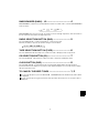
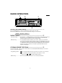
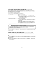
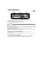
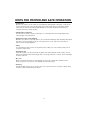
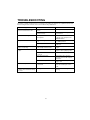
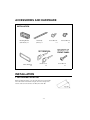
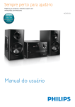
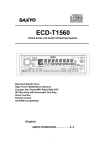
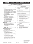
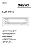
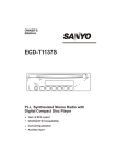
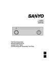
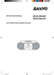
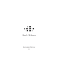
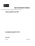
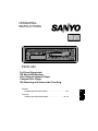
OPERATING
INSTRUCTIONS
FXCD-550
Full Panel Detachable
FM Stereo/AM Receiver
Auto Reverse Cassette Player
Compact Disc Player
ISO Mounting with Removable Trim Ring
(English)
OPERATING INSTRUCTIONS . . . . . . . . . . . . . . . . . . . 1~25
GB
(Español)
LIBRITO DE INSTRUCCIONES . . . . . . . . . . . . . . . . . 26~49
E
SANYO MOBILE AUDIO
MODEL FXCD-550
LIMITED WARRANTY
OBLIGATIONS
In order to obtain warranty service, the product must be delivered to and picked up from an Authorized Sanyo Factory Service Center at the
user's expense, unless specifically stated otherwise in this warranty. The names and addresses of Authorized Sanyo Service Cente r may be
obtained by calling the toll-free number listed below.
For product operation, authorized service center referral, service assistance or problem resolution, call
CUSTOMER INFORMATION 1-800-421-5013
Weekdays 8:00 AM - 5:00 PM Pacific Time
For accessories and/or parts not available from an authorized dealer, call
PARTS ORDER INFORMATION 1-800-726-9662
Weekdays 8:00 AM - 5:00 PM Pacific Time
THIS WARRANTY IS VALID ONLY ON SANYO PRODUCTS PURCHASED AND USED IN THE UNITED STATES OF
AMERICA. THIS WARRANTY APPLIES ONLY TO THE ORIGINAL RETAIL USER, AND DOES NOT APPLY TO PRODUCTS USED FOR ANY INDUSTRIAL, PROFESSIONAL OR COMMERCIAL PURPOSE. THE ORIGINAL DATED BILL
OR SALE OR SALES SLIP MUST BE SUBMITTED TO THE AUTHORIZED SANYO SERVICE CENTER AT THE TIME
WARRANTY SERVICE IS REQUESTED.
Subject to the OBLIGATIONS above and EXCLUSIONS below, SANYO FISHER COMPANY(SFC) warrants this SANYO product against defects in materials and workmanship for the periods specified below. SFC will repair or replace (at its option) the product and any of its parts
which fail to conform to this warranty. The warranty period commences on the date the product was first purchased at retail.
LABOR
PARTS
1 YEAR
1 YEAR
EXCLUSIONS
This warranty does not cover (A) the adjustment of customer-operated controls as explained in the appropriate model's instruction manual, or
(B) the repair of any product whose serial number has been altered, defaced or removed.
This warranty shall not apply to the cabinet or cosmetics parts, knobs or routine maintenance.
This warranty does not apply to uncrating, setup, installation, removal of the product for repair or reinstallation of the product after repair.
This warranty does not apply to repairs or replacements necessitated by any cause beyond the control of SFC including, but not imited
l
to,
any malfunction, defect or failure caused by or resulting from unauthorized service or parts, improper maintenance, operation contrary to furnished instructions, shipping or transit accidents, modification or repair by the user, abuse, misuse, neglect, accident, incorrect power line
voltage, fire, flood or other Acts of God, or normal wear and tear.
The foregoing is in lieu of all other expressed warranties and SFC does not assume or authorize any party to assume for it any other obligation
or liability.
THE DURATION OF ANY WARRANTIES WHICH MAY BE IMPLIED BY LAW (INCLUDING THE WARRANTIES OF
MERCHANTABILITY AND FITNESS) IS LIMITED TO THE TERM OF THIS WARRANTY. IN NO EVENT SHALL SFC BE
LIABLE FOR SPECIAL, INCIDENTAL OR CONSEQUENTIAL DAMAGES ARISING FROM OWNERSHIP OR USE OF
THIS PRODUCT, OR FOR ANY DELAY IN THE PERFORMANCE OF ITS OBLIGATIONS UNDER THIS WARRANTY
DUE TO CAUSES BEYOND ITS CONTROL. SOME STATES DO NOT ALLOW LIMITATIONS ON HOW LONG AN IMPLIED WARRANTY LASTS AND/OR DO NOT ALLOW THE EXCLUSION OR LIMITATION OF CONSEQUENTIAL DAMAGES, SO THE ABOVE LIMITAIONS AND EXCLUSIONS MAY NOT APPLY TO YOU.
THIS WARRANTY GIVES YOU SPECIAL LEGAL RIGHTS. YOU MAY HAVE OTHER RIGHTS, WHICH VARY FROM
STATE TO STATE.
ATTENTION
For your protection in the event of theft or loss of this product, please fill in the information below for your own personal records.
Model No.
Serial No.
(Located on back or bottom side of unit)
Date of Purchase
Purchase Price
Where Purchased
WARNING : TO PREVENT FIRE OR SHOCK HAZARD, DO NOT EXPOSE THIS APPLIANCE TO RAIN OR MOISTURE.
-1-
English
CONTENTS
COMPACT DISC CARE. . . . . . . . . . . . . . . . . . . . . . . . . . . . . . . . . . . . . . . . . . . . . . . . . . . . . . . 3
DIGITAL DISPLAY . . . . . . . . . . . . . . . . . . . . . . . . . . . . . . . . . . . . . . . . . . . . . . . . . . . . . . . . . . . 5
DETACHABLE FRONT PANEL . . . . . . . . . . . . . . . . . . . . . . . . . . . . . . . . . . . . . . . . . . . . . . . . . 6
GENERAL OPERATION . . . . . . . . . . . . . . . . . . . . . . . . . . . . . . . . . . . . . . . . . . . . . . . . . . . . . . 7
RADIO OPERATION . . . . . . . . . . . . . . . . . . . . . . . . . . . . . . . . . . . . . . . . . . . . . . . . . . . . . . . . . 9
TAPE OPERATION . . . . . . . . . . . . . . . . . . . . . . . . . . . . . . . . . . . . . . . . . . . . . . . . . . . . . . . . . 11
CD OPERATION . . . . . . . . . . . . . . . . . . . . . . . . . . . . . . . . . . . . . . . . . . . . . . . . . . . . . . . . . . . 13
ERROR SIGNS . . . . . . . . . . . . . . . . . . . . . . . . . . . . . . . . . . . . . . . . . . . . . . . . . . . . . . . . . . . . 15
CLOCK. . . . . . . . . . . . . . . . . . . . . . . . . . . . . . . . . . . . . . . . . . . . . . . . . . . . . . . . . . . . . . . . . . . 16
HINTS FOR PROPER AND SAFE OPERATION . . . . . . . . . . . . . . . . . . . . . . . . . . . . . . . . . . 17
TROUBLESHOOTING . . . . . . . . . . . . . . . . . . . . . . . . . . . . . . . . . . . . . . . . . . . . . . . . . . . . . . . 18
ACCESSORIES AND HARDWARE. . . . . . . . . . . . . . . . . . . . . . . . . . . . . . . . . . . . . . . . . . . . . 19
INSTALLATION . . . . . . . . . . . . . . . . . . . . . . . . . . . . . . . . . . . . . . . . . . . . . . . . . . . . . . . . . . . . 19
UNIT REMOVAL . . . . . . . . . . . . . . . . . . . . . . . . . . . . . . . . . . . . . . . . . . . . . . . . . . . . . . . . . . . 22
ELECTRICAL CONNECTIONS . . . . . . . . . . . . . . . . . . . . . . . . . . . . . . . . . . . . . . . . . . . . . . . . 23
LINE OUT CONNECTIONS . . . . . . . . . . . . . . . . . . . . . . . . . . . . . . . . . . . . . . . . . . . . . . . . . . . 24
SPECIFICATIONS . . . . . . . . . . . . . . . . . . . . . . . . . . . . . . . . . . . . . . . . . . . . . . . . . . . . . . . . . . 25
NOTE
This equipment has been tested and found to comply with the limits for a Class B digital device,
pursuant to Part 15 of the FCC Rules. These limits are designed to provide reasonable protection
against harmful interference in a residential installation. This equipment generates, uses, and can
radiate radio frequency energy and, If not installed and used in accordance with the instructions, may
cause harmful interference to radio communications. However, there is no guarantee that interference
will not occur in a particular installation. If this equipment does cause harmful interference to radio or
television reception, which can be determined by turning the equipment off and on, the user is
encouraged to try to correct the interference by one or more of the following measures:
- Reorient or relocate the receiving antenna.
- Increase the separation between the equipment and receiver.
- Connect the equipment into an outlet on a circuit different from that to which the receiver is connected.
- Consult the dealer or an experienced radio/TV technician for help.
CAUTION
• This unit is designed to operate on 12 volts DC, NEGATIVE ground electrical systems only.
• When fuse replacement is necessary, use only a 15 amp fuse. Do not replace with a higher rated fuse.
If the fuse blows often, carefully check all electrical connections for any short circuits and have your
car's voltage regulator checked also.
• Do not install the unit where it will be exposed to direct sunlight or hot air discharged from the car heater.
• Do not expose the unit to water or moisture.
• To avoid damaging the unit, never insert anything other than a compact disc into the disc slot.
• This unit should not be adjusted or repaired by anyone except qualified service personnel.
If servicing is required, return the unit to an authorized SANYO mobile audio dealer.
• Use of controls or adjustments or performance of procedures other than those specified herein may
result in hazardous radiation exposure.
• Changes or modifications not expressly approved by Sanyo may void the user's authority to operate
this equipment.
-2-
COMPACT DISC CARE
Dirt, dust, scratches and warpage can cause a deterioration in the sound or intermittent skipping some tracks
during play.
• This unit has been designed to play compact discs
bearing the identification logo shown on the left.
Discs bearing other types of identification logos
may not play properly.
• Playback may not be possible due to the
characteristics of the CD recorder or the CD-R/RW
used, or due to scratches or dirt on the CD.
• For some CD-R/RWs, depending on the quality
of their recording or storage media used, playback
may not be possible due to deterioration of
recorded of material.
• Do not use non-conventional discs such as
heart-shaped, octagonal discs, etc.
The player could be damaged.
Label Side
• Fingerprints and dust should be carefully wiped
from the signal surface of the disc (glossy side) with
a soft cloth.
Wipe in a straight motion from the inside to the
outside of the disc. Unlike conventional records,
the compact disc has no grooves to collect dust and
debris. Small dust particles will have no effect on
reproduction quality.
• Do not insert a disc which is cracked into the unit.
• Do not apply paper or write anything on the disc.
• To prevent warping the disc, do not expose it to
direct sunlight, high humidity or high temperatures
for extended periods.
-3-
Benzene Thinner Cleaning spray
• Never use chemicals such as record cleaning
sprays, antistatic sprays or fluids, benzene or
thinner to clean compact discs. These chemicals
will permanently damage the plastic surface of
the disc.
• When not using the disc player for extended
periods, remove the compact disc and return it to
the plastic storage case. This will protect the disc
from dust and exposure to the sun.
• Mixed-mode CDs
This product can only play audio tracks on mixed-mode CDs.
The initial track contains non-audio data, and so it does not produce any sound.
Playback will start from the next track.
(Mixed-mode CDs are CDs which contain both non-audio data and audio tracks.)
• CDs containing copy control protection technology.
It is possible that some CDs with copy control protection (added to prevent computer
duplication) may not play on this unit.
This is due to the CD with copy control protection not conforming to CD standards and is
not due to a malfunction of this unit.
If there are any problems playing a CD with copy control protection, consult the store where
the CD was purchased.
-4-
DIGITAL DISPLAY
Automatic Music Select System (AMSS)
Metal Display
Tape playing direction
Disc in
BASSXPANDER
Auto Travel Preset (ATP)
AM Band
FM Bands
Radio Frequency, Time,
CD Track Number,
Audio Control Selection,
Scan Play, Repeat Play,
Shuffle Play, Error Signs,
no Cd, no TAPE,
TAPE play
-5-
Preset Channel,
Auto Travel
Preset Channel
DETACHABLE FRONT PANEL
The front panel is designed to be removable for antitheft purposes.
It is recommended that you remove and carry the front panel with you when you leave your car.
A carrying case is provided with the unit for this purpose.
HOW TO DETACH THE FRONT PANEL
RELEASE KNOB
1 Press the release knob (REL) to release the front panel.
2 Pull the entire panel to remove it from the unit.
HOW TO REPLACE THE FRONT PANEL
Align the right side of the panel with the stopper,
and then push the left side of the panel into the
unit until it clicks.
FRONT PANEL
Note
The unit will not operate if it is installed incorrectly.
FRONT PANEL FIXING
The front panel can be installed so that it cannot be removed
to prevent theft or loss. Using the screw included with the
accessory kit, install it to the right side of the front panel.
CAUTION
• Do not attempt to remove the panel in a manner other than that described above.
• When installing the panel, do not force it into the unit.
• Do not touch the connection terminals of the panel or the unit. It may cause poor
contact.
• Use a clean, dry cloth when cleaning the terminals.
• Keep the panel out of direct sunlight and high temperatures.
• Prevent the panel from coming into contact with benzene, thinner, or insecticides.
• Do not drop the panel.
• Do not attempt to remove the radio front panel that takes your attention away from safety
driving you vehicle.
-6-
GENERAL OPERATION
4
8
7 6 5
1
3
2
TURNING THE POWER ON ........................................ 1
when ACC is on.
TURNING THE POWER OFF ...................................... 1
Press the ON/OFF button to stop the current operation.
Install the front panel and press the ON/OFF button
The button dims when the power is off (ACC on).
ELECTRONIC CONTROLS ......................................... 2, 3
Press the SEL button to select the audio functions as shown in the table below.
To adjust the volume, press the
or
buttons
while in the volume mode. To adjust the bass, treble,
balance or fader, press the SEL button to select the desired operation, then press the
or
buttons.
Note
While no other mode is displayed, the the
or
MODE
buttons function as a volume control.
(Max)
(Min)
bAS (bass)
Down
-5
Up
5
TRE (treble)
Down
-5
Up
5
bAL (balance)
Left
L15
Right
R15
FAd (fader)
Rear
R15
Front
F15
VOL (volume)
Down
0
Up
50
ELECTRONIC CONTROL RESET................................ 2
Press the SEL button
be reset.
for about 3 seconds until the unit beeps, the audio controls, except for volume, will
-7-
BASSXPANDER (BASX) - 1/2 ..................................... 4
BASSXPANDER is a dual-mode sound equalization feature. Press button
mode as follows;
b-1
b-2
to select the BASSXPANDER
OFF
BASSXPANDER offers two preset mode: b-1 enhances the low and high frequencies, while b-2 enhances
the low frequencies and reduces the high frequencies.
RADIO SELECTION BUTTON (BND) ........................... 5
Press the BND button to switch from CD player, or tape mode to radio.
Each time the button is pressed, the function changes as shown below.
FMI
FMII
AM
TAPE SELECTION BUTTON (TAPE) ............................ 6
Press the TAPE button
with a tape slot to switch from radio or CD player mode to tape mode.
CD SELECTION BUTTON (CD) ................................... 7
Press the CD button
with a CD slot to switch from radio or tape mode to CD player mode.
CLOCK BUTTON (DISP) ............................................ 8
Press the DISP button to switch between the clock and audio display. When an audio function is
performed while the time display is selected, the audio display will appear for 5 seconds, then the display
will return to the time mode.
TO CANCEL THE BEEP TONES ................................. 1, 2
1 To cancel the beep tones, press the SEL button
is displayed.
and ON/OFF button simultaneously until “b : OFF”
2 To turn on the beep tones again, perform the same procedure. The beep tones are set and “b : On” is
displayed.
-8-
RADIO OPERATION
2
4
1
3
SELECTING RADIO MODE ........................................ 1
Press the BND button to switch from CD player or tape mode to the radio.
Each time the BND button is pressed, the selected band changes as shown below.
FMI
FMII
AM
RADIO TUNING ........................................................ 2
• Automatic tuning ............ Press the FF + or - REW button for more than 0.5 second until it beeps twice if
the beep tones are on. When the button is released, the system will start
automatic tuning and stop at the next receivable station.
• Manual tuning ................ To select higher frequency stations, press the FF + button for less than 0.5
seconds.To select lower frequency stations, press the - REW button for less than
0.5 seconds. To quickly scan up or down in frequency, press and hold the FF +
or - REW button. Release the button when the display approaches the desired
frequency, then press and release the button repeatedly until the desired
frequency is displayed.
STORING PRESET STATIONS ................................... 3
The preset buttons can be used to store 6 stations in each band (FMI, FMII and AM) for convenient
access to your favorite stations.
• Programming stations..... 1 Select the desired band, then tune in the station you want to store in memory.
2 Press and hold one of the preset buttons for more than 2 seconds.
Repeat steps 1 and 2 to program additional stations.
• Quick tuning.................... Select the desired band, then press one of the six preset buttons.
-9-
ATP (AUTO TRAVEL PRESET) OPERATION ................ 4
The Auto Travel Preset function searches for and memorizes the 6 strongest stations in one of the two
bands (FM, AM) in the order of signal strength.
This feature is useful when you are driving in an unfamiliar location and want to memorize local stations
without changing the standard preset stations.
A total of 12 stations (6 FM and 6 AM) can be programmed.
• To set the stations............................... 1 Select the desired band.
2 Press and hold the ATP button
for more than 2 seconds.
“ATP” appears in the display.
When the stations have been memorized, scanning stops and the
strongest station is selected.
• Quick Tuning of ATP Stations ................. 1 Select the desired band.
2 Press the ATP button if the “ATP” indicator does not appear in
the display.
3 While ATP is illuminated, press the ATP button and the unit
seeks ATP1-6. If there is no preset ATP, - 0 - appears in the
display.
• To scan programmed stations............. See “PRESET-SCAN-BUTTON OPERATION”.
Notes
• If no station can be received, “- 0 -” appears in the display.
• If fewer than 6 stations can be received, the system will memorize as many stations as
possible, then select the strongest one.
• If ATP mode is selected in FMII band, FMI ATP mode is selected.
To cancel the ATP, press the BND button
mode is canceled.
. When ATP is canceled, the ATP indicator disappears and ATP
PRESET-SCAN-BUTTON OPERATION ........................ 1, 4
This function scans each of the preset stations stored in the selected band (both manual preset and
auto travel presets).
1 Select the desired band or ATP mode.
for FMI, FMII or AM. Press the ATP button to select the ATP mode.
for more than 2 seconds. The system will select and receive each preset station
Press the BND button
2 Press the BND button
for five-second.
3 To stop scanning and retain the station currently selected, press the BND button
five-second period.
-10-
again during this
TAPE OPERATION
5 4
2
3
1
9 8
7 6
LOADING AND EJECTING THE TAPE ......................... 1, 2
Insert a cassette into the tape slot and the tape player will start.
Press the eject button to eject a tape.
CAUTION
• Only cassette tapes that play no longer than 90 minutes should be used. Tapes exceeding 90 minutes
are thin and may easily break.
SELECTING TAPE MODE .......................................... 3
Inserting a cassette into the tape slot as start the tape player. If radio, CD player is in operation with a tape
loaded, press the TAPE button to switch to tape mode.
SWITCHING THE TAPE DIRECTION ........................... 3
Press the TAPE button .
When the tape reaches the end of one side, the unit will automatically switch to the opposite side of the tape.
FAST FORWARD AND REWIND ................................. 4, 5
Press the FF + button to fast forward and press the - REW button to rewind the tape.
Pressing the TAPE button during fast forward and rewind operation resumes tape playing.
-11-
LOCATING THE BEGINNING OF A PROGRAM
(AMSS) .................................................................... 4, 5, 6
This system is equipped with a function that allows you to skip forward or backward to locate the beginning
of a particular selection on the tape. (Automatic Music Select System : AMSS)
. "AMSS TAPE" is displayed.
to skip forward up to 9 selections from the current location on the tape.
e.g.) With "AMSS TAPE" displayed, press button three times. "AMSS F3" is displayed.
1 Press the AMSS button
2 Press the FF + button
The system will search for 3 blank spaces between selections in the forward direction, then begin
playing the third selection from the starting point.
3 Press the - REW button
to skip backward to the beginning of the current selection, or up to 8 selections
from the current location on the tape.
e.g.) With "AMSS TAPE" displayed, press button five times. "AMSS R5" is displayed.
The system will search for 5 blank spaces between selections in the backward direction, then begin
playing the forth selection from the starting point. (The blank space before the current selection
counts as one blank space.)
4 To cancel AMSS mode, press button
again.
Notes
• If AMSS detects 15 seconds of blank space, it will automatically advance the tape
to the next selection.
• AMSS may not operate properly if
• A tape was recorded at a low level.
• A tape has long, silent intervals.
• A tape is a live recording.
METAL PLAY MODE ................................................. 7
If a metal or high-position tape is used, press the MTL button
is indicated.
to make the player in metal play mode. MTL
SCAN MODE ............................................................ 8
Scan helps to find a program by playing about the first 10 seconds of each selection.
Press the SCN button during play to start scan operation. "SCn" is displayed.
To cancel scan, press the SCN button again.
REPEAT MODE ......................................................... 9
This operation makes it possible to listen repeatedly to a selection.
Press the RPT button ➈ during play. "RP" is displayed, the selection playing will continue until RPT is
pressed again.
Notes
RPT/SCN may not operate properly if
• A tape was recorded at a low level.
• A tape has long, silent intervals.
• A tape is a live recording.
-12-
CD OPERATION
2 5 4
1
3
6 7 8
LOADING AND EJECTING THE CD ............................ 1, 2
Insert a disc into the CD slot and the CD player will start playing.
Press the eject button to eject a disc.
CAUTION
• This CD player is not designed for 8 cm CDs.
Please do not use an 8 cm CD nor 8 cm CD adaptor.
• If the unit is already loaded with a CD, please do not attempt to insert another disc,
which may result in damage to both of the discs and the unit.
SWITCHING TO CD MODE ......................................... 3
Press the CD button to switch from radio or tape mode to CD player mode.
When the CD mode is switched on while a disc is loaded, play resumes from the point at which play was
stopped.
When the entire disc has played, the unit returns to the first track and play resumes.
The CD player continues playing the disc until the ON/OFF button is pressed, the other mode is selected, or
the disc is ejected.
-13-
SKIPPING TRACKS ................................................... 4, 5
Press the FF + button to skip to the beginning of the next track.
Press the - REW button to skip to the beginning of the track currently playing.
Press the - REW button twice to skip to the beginning of the previous track.
Press and hold the FF + or - REW button for more than 0.5 seconds to search quickly
(with sound) in the forward or reverse direction.
When the button is released, the CD resumes normal play.
SHUFFLE MODE ....................................................... 6
This function plays the tracks on a CD in random order.
Press the SHF button
to begin shuffle play. The SHF indicator lights.
Press the FF + or - REW button to select another random track.
To cancel this mode, press the SHF button again or eject the CD.
Notes
If a disc is already loaded under the following conditions, shuffle play will resume
from the point at which play was stopped:
• If the vehicle ignition is turned off, then on again.
• If the power is switched off, then on again with the ON/OFF button.
REPEAT MODE ......................................................... 7
Press the RPT button to play the current track repeatedly. The RPT indicator lights.
To cancel this mode, press the RPT button again or eject the CD.
Notes
If a disc is already loaded under the following conditions, repeat play will resume:
• If the vehicle ignition is switched off, then on again.
• If the power is switched off, then on again with the ON/OFF button.
SCAN MODE (PLAYING THE BEGINNING
OF EACH TRACK) ..................................................... 8
This function plays the first 10 seconds of each track sequentially.
Press the SCN button to begin the scan mode. The SCN indicator lights.
To cancel this mode, press the SCN button again.
Note
Scan mode will be canceled when the vehicle ignition is turned off, or when the disc
is ejected.
-14-
ERROR SIGNS
CD Player
If a problem should occur while operating the built-in CD player, one of the following error signs
may be displayed:
Error Sign
Cause
Remedy
Abnormal mechanism function.
Press the eject button.
Turn the power off and then on again.
If it is not corrected, contact the place
of purchase.
The disc is inserted incorrectly.
Eject the disc and insert it properly.
The disc is dirty.
Clean the disc.
The disc is defective.
Use another disc.
There is condensation on the
optical lens.
Leave the disc player off for an hour
or so, then try again.
Internal connection check error.
Turn the power off and then on again.
If it is not corrected, contact the place
of purchase.
-15-
CLOCK
3 2
1
4
DISPLAY MODE CHANGE.......................................... 1
The display on the unit can be changed by pressing DISP button . Press the DISP button to switch
between the clock and audio display. When a radio, tape and CD function is performed while the time display
is selected, the audio display will appear for 5 seconds, then the display will return to the time mode.
ADJUSTING THE TIME .............................................. 1, 2, 3
To adjust the time, press the DISP button for more than 2 seconds. The time display blinks.
To adjust the minute, press the FF + button .
To adjust the hour, press the - REW button .
To advance the time rapidly, hold the FF + or - REW button continuously.
Press DISP button again to start the clock.
CLOCK RESET ......................................................... 1, 4
Press DISP button for more than 2 seconds and the time display blinks. While blinking, press preset
button 6 to skip to the nearest half-hour as follows:
Example: 3:00 ~ 3:29
3:30 ~ 3:59
3:00
4:00
Notes
• This unit uses a 12-hour clock.
• The clock function and radio presets are retained in memory when the audio is switched off.
-16-
HINTS FOR PROPER AND SAFE OPERATION
• Condensation
Moisture can condense on the optical lens of the CD player during humid or rainy days, or after the car
heater is turned on. If this occurs the disc player may not function properly. To remedy the situation,
remove the disc from the unit and wait approximately one hour. This should allow the moisture to
evaporate and restore normal operation.
• Temperature Consideration
The unit may not operate correctly in extremely hot or cold temperatures. Avoid exposing the unit to
extremely high or low temperatures.
• Interruptions in the sound (skipping)
When the car is driven on very rough surfaces, the sound from the CD player may skip and be interrupted.
This will not cause any damage to the disc or the player. If this occurs, wait for the road surface to
improve before using the CD player.
• Safety
For safer driving, keep the volume at a moderate level to enable you to hear outside sounds (such as
emergency vehicle sirens).
• Cleaning the unit
Clean the unit with a soft, dry cloth. Stains should be removed by wiping the surfaces with a soft cloth
immersed in lukewarm water and wrung dry. Never use strong chemicals or solvents. These will damage
the finish of the unit.
• Disc care
When not using the disc player for extended periods, remove the compact disc and return it to the
plastic storage case. Do not leave a disc partially ejected from the player.
• Servicing
Should a problem develop, do not open the unit or try to repair it yourself. If servicing is required, bring
the unit to a Sanyo Authorized Service Center.
-17-
TROUBLESHOOTING
Sometimes a simple operational error or a mistake in the wiring can appear to be a problem with the unit.
Before having the unit serviced, refer to the troubleshooting chart below.
Symptom
The compact disc does not play
when inserted into the unit.
Cause
Solution
The volume control is turned
down.
Turn up the volume control.
The power connections are not
wired correctly.
Check the +12V and ground
connections.
No sound is coming out.
The speaker code connection is
imcomplete.
Check the connection of the
speaker code, and press the
ON/OFF button.
No power.
The vehicle ignition is switched
off.
Switch the ignition to the "ON"
or "ACC" position.
The fuse is blown.
Replace the fuse with another
15A fuse.
The unit does not work properly
(Eject, Load, Play).
The microcomputer has been
affected by electrical noise.
Eject the disc, then insert it
again.
The sound from the CD player
skips.
The road surface is rough.
Wait for the road surface to
improve before playing a disc.
The unit is not mounted
securely.
Install the unit securely.
The disc is defective.
Try another disc. If it plays
properly, the first disc may be
defective.
The disc is dirty.
Clean the disc as explained on
pages 3-4.
No radio reception.
The antenna cable is not
connected.
Insert the antenna cable firmly
into the antenna jack on the
unit.
The radio does not stop on any
stations when automatic tuning
is used.
The signals are weak.
Select a station using manual
tuning.
-18-
ACCESSORIES AND HARDWARE
Mounting Bracket
(Half Sleeve) x 1
Rear Strap
(Brace) x 1
Removable Trim Ring
x1
Screw M5 x 14
x1
Unlock Levers
x2
INSTALLATION
1. BEFORE INSTALLATION
When mounting the unit in a car, keep the unit as level as possible.
If the unit must be mounted at an angle, due to the design of the
vehicle, make sure the unit does not tilt by more than 30°.
-19-
Hex bolt M5 x 8
x1
Screw M2 x 8
x1
2. ISO MOUNTING WITH REMOVABLE TRIM RING
When mounting the unit into a DIN-standard cutout (182 × 53 mm) in the dashboard or
console, attach the provided Removable Trim Ring to the unit.
DASHBOARD OR CONSOLE
182 mm
AUDIO UNIT
53 mm
REMOVABLE TRIM RING
3. INSTALLATION PROCEDURES
M5 x 14
HEX BOLT
REAR STRAP
(BRACE)
DASHBOARD
OR CONSOLE
182 mm
53 mm
REMOVABLE
TRIM RING
MOUNTING BRACKET
(HALF SLEEVE)
AUDIO UNIT
1.
2.
3.
4.
Insert the mounting bracket into the DIN-standard cutout (182 × 53 mm) in the dashboard or console.
Bend the mounting bracket stopper outward until the bracket fits snugly in the cutout.
Push the unit into the mounting bracket until it locks in place.
Secure the rear strap to the audio unit and vehicle dashboard.
-20-
4. Installation to TOYOTA/NISSAN Vehicles
Install the unit using the existing TOYOTA/NISSAN Mounting Bracket and Screws. Use mounting holes in
the unit chassis. "T" or "N" is engraved next to each mounting hole. Use "T" holes for Toyota vehicles and
"N" holes for Nissan vehicles.
TOYOTA/NISSAN
Mounting Bracket
Screw
CAUTION
ONLY USE M5 x 6 SCREW
(NOT INCLUDED WITH THIS
UNIT) AS ILLUSTRATED ABOVE.
USE OF ANY OTHER SCREW OR
HARDWARE MAY RESULT DAMAGE
TO HEAD UNIT.
Screw
-21-
UNIT REMOVAL
AUDIO UNIT
3
2
2
3
3
UNLOCK LEVERS
1. Remove the front panel by pressing the release knob.
2. Insert the unlock levers into the slots as illustrated.
Note
The jagged side of the key should face outward.
3. Slide down keys outward and pull to remove the audio unit.
-22-
ELECTRICAL CONNECTIONS
1. ANTENNA SOCKET
ANTENNA PLUG
2-speaker System
4-speaker System
(White)
(White/Black)
(Gray)
(Gray/Black)
(Green)
(Green/Black)
(Violet)
(Violet/Black)
Front Left
Speaker
2.
3.
4.
5.
6.
(White)
(White/Black)
(Gray)
(Gray/Black)
(Green)
(Green/Black)
(Violet)
(Violet/Black)
Front Right
Speaker
Rear Left
Speaker
Rear Right
Speaker
+12V Constant Power Supply (Yellow)
+12V Accessory/Switched (Red)
Ground Wire (Black)
Power Antenna (Blue/Red)
Amplifier Turn On (Blue/White)
Left
Speaker
Right
Speaker
Do Not
Connect
Do Not
Connect
CAUTION
• DO NOT connect any speaker wires to the metal body or chassis of the vehicle.
• DO NOT connect the speaker common (-) wires to each other.
• Connect each speaker wire directly to each speaker terminal.
• All speaker common (-) wires must remain floating.
1 Antenna socket
• Insert the plug from the antenna installed in your vehicle into this socket. (If your vehicle has a dual
antenna system, a dual antenna to single antenna cable adaptor may be required.)
2 +12V Constant Power Supply (Yellow)
• Connect this wire to the +12V power terminal which receives power continuously.
• Connect to location drawing 10 A amperage or more.
3 +12V Accessory/Switched (Red)
• Connect this wire to the terminal which receives power while the ignition switch is at ON or
ACCESSORY position.
• If the ignition switch does not have an ACC position, connect this wire to a +12V
power terminal which receives power continuously. (Same as item 2.)
• Connect to location drawing 100 mA amperage or more.
4 Ground wire (Black)
• Connect this wire to the vehicle chassis.
5 Power Antenna (Blue/Red)
• Connect this wire to the control terminal of a Power Antenna.
• When not using a Power Antenna, this wire is not connected.
6 Amplifier Turn On (Blue/White)
• Connect this wire to an external amplifier.
• When not using an external amplifier, this wire is not connected.
-23-
Notes
• When using a two-speaker installation, the Green, Green/Black, Violet, Violet/Black wires,
which are used for a four-speaker installation, are not used. The ends of these wires must
be covered with electrical tape to prevent them from shorting to the unit or the vehicle chassis.
• When using a two-speaker installation, set the
FADER control to the center position.
• When fuse replacement is necessary remove
the blown fuse by using pliers.
Then install the new 15 amp. fuse.
Fuse 15A
NG
OK
Burnt
LINE OUT CONNECTIONS
• The unit has a line output terminals. You can use a separate amplifier to upgrade your system.
RCA Line-out Jacks
OUTPUT
FRONT REAR
White
L (eft)
R (ight)
Red
External
Amplifier
Rear Speaker
Front Speaker
RCA Line-out Jacks (For Speakers)
• Connect a patch cable (not supplied) from the White (left channel) and Red (right channel) RCA line output
jacks to the line input terminals of the external amplifier.
-24-
SPECIFICATION
FM TUNER SECTION
Frequency Range . . . . . . . . . . . . . . . . . . . . . . . . . . . . . . . . . . . . . . . . . . . . . . . . . . 87.5MHz~107.9MHz
Usable Sensitivity . . . . . . . . . . . . . . . . . . . . . . . . . . . . . . . . . . . . . . . . . . . . . . . . . . . . . . . . . . . . . . 15dBf
50dB Quieting Sensitivity . . . . . . . . . . . . . . . . . . . . . . . . . . . . . . . . . . . . . . . . . . . . . . . . . . . . . . . . . 30dBf
Frequency Response (±3dB) . . . . . . . . . . . . . . . . . . . . . . . . . . . . . . . . . . . . . . . . . . . . . . 50Hz~12.5kHz
I.F. Rejection . . . . . . . . . . . . . . . . . . . . . . . . . . . . . . . . . . . . . . . . . . . . . . . . . . . . . . . . . . . . . . . . . .100dB
Image Rejection . . . . . . . . . . . . . . . . . . . . . . . . . . . . . . . . . . . . . . . . . . . . . . . . . . . . . . . . . . . . . . . . .65dB
Signal-to-Noise Ratio . . . . . . . . . . . . . . . . . . . . . . . . . . . . . . . . . . . . . . . . . . . . . . . . . . . . . . . . . . . . . 60dB
Selectivity. . . . . . . . . . . . . . . . . . . . . . . . . . . . . . . . . . . . . . . . . . . . . . . . . . . . . . . . . . . . . . . . . . . . . .65dB
Stereo Separation . . . . . . . . . . . . . . . . . . . . . . . . . . . . . . . . . . . . . . . . . . . . . . . . . . . . . . . . . . . . . . . 27dB
Capture Ratio. . . . . . . . . . . . . . . . . . . . . . . . . . . . . . . . . . . . . . . . . . . . . . . . . . . . . . . . . . . . . . . . . . . .2dB
Antenna Impedance. . . . . . . . . . . . . . . . . . . . . . . . . . . . . . . . . . . . . . . . . . . . . . . . . . . . . . . . . . . . . . 75Ω
AM TUNER SECTION
Frequency Range . . . . . . . . . . . . . . . . . . . . . . . . . . . . . . . . . . . . . . . . . . . . . . . . . . . . . 530kHz~1710kHz
Usable Sensitivity (S/N 20dB) . . . . . . . . . . . . . . . . . . . . . . . . . . . . . . . . . . . . . . . . . . . . . . . . . . . . . 20µV
I.F. Rejection . . . . . . . . . . . . . . . . . . . . . . . . . . . . . . . . . . . . . . . . . . . . . . . . . . . . . . . . . . . . . . . . . . .80dB
Image Rejection . . . . . . . . . . . . . . . . . . . . . . . . . . . . . . . . . . . . . . . . . . . . . . . . . . . . . . . . . . . . . . . . .75dB
S/N Ratio . . . . . . . . . . . . . . . . . . . . . . . . . . . . . . . . . . . . . . . . . . . . . . . . . . . . . . . . . . . . . . . . . . . . . .50dB
Antenna Impedance . . . . . . . . . . . . . . . . . . . . . . . . . . . . . . . . . . . . . . . . . . . . . . . . . . . . . . . . . . . . . 75Ω
TAPE SECTION
Wow and Flutter. . . . . . . . . . . . . . . . . . . . . . . . . . . . . . . . . . . . . . . . . . . . . . . . . . . . . . . . . . . . . . . . . 0.1%
S/N Ratio (Normal) . . . . . . . . . . . . . . . . . . . . . . . . . . . . . . . . . . . . . . . . . . . . . . . . . . . . . . . . . . . . . . 52dB
Separation . . . . . . . . . . . . . . . . . . . . . . . . . . . . . . . . . . . . . . . . . . . . . . . . . . . . . . . . . . . . . . . . . . . . .50dB
Frequency Response. . . . . . . . . . . . . . . . . . . . . . . . . . . . . . . . . . . . . . . . . . . . . . . . . . . . . . 50Hz–15kHz
CD SECTION
Disc size . . . . . . . . . . . . . . . . . . . . . . . . . . . . . . . . . . . . . . . . . . . . . . . . . . . . . . . . . . . . . . . . . . . . . . . . 5”
Channels . . . . . . . . . . . . . . . . . . . . . . . . . . . . . . . . . . . . . . . . . . . . . . . . . . . . . . . . . . . . 2-channel stereo
Sampling Frequency . . . . . . . . . . . . . . . . . . . . . . . . . . . . . . . . . . . . . . . . . . . . . . . . . . . . . . . . . . 44.1kHz
D/A Converter . . . . . . . . . . . . . . . . . . . . . . . . . . . . . . . . . . . . . . . . . . . . . . . . . . . . . . . . . . . . . Twin, 1–bit
Pickup . . . . . . . . . . . . . . . . . . . . . . . . . . . . . . . . . . . . . . . . . . . . . . . Optical 3-beam semiconductor laser
Digital Filter . . . . . . . . . . . . . . . . . . . . . . . . . . . . . . . . . . . . . . . . . . . . . . . . . . . . . . . . . . . . . . . . . . . . . 4 fs
Frequency Response. . . . . . . . . . . . . . . . . . . . . . . . . . . . . . . . . . . . . . . . . . . . . . . . . . . . . . 20Hz~20kHz
Total Harmonic Distortion . . . . . . . . . . . . . . . . . . . . . . . . . . . . . . . . . . . . . . . . . . . . . . . . . . 0.1% (1 kHz)
Dynamic Range . . . . . . . . . . . . . . . . . . . . . . . . . . . . . . . . . . . . . . . . . . . . . . . . . . . . . . . . . . . . . . . . .85dB
Signal-to-Noise Ratio . . . . . . . . . . . . . . . . . . . . . . . . . . . . . . . . . . . . . . . . . . . . . . . . . . . . . . . . . . . . . 90dB
Wow and Flutter. . . . . . . . . . . . . . . . . . . . . . . . . . . . . . . . . . . . . . . . . . . . . . . . . Below measurable limits
Channel Separation (1kHz) . . . . . . . . . . . . . . . . . . . . . . . . . . . . . . . . . . . . . . . . . . . . . . . . . . . . . . . . 85dB
AUDIO SECTION
RMS Power Rating (3% THD) . . . . . . . . . . . . . . . . . . . . . . . . . . . . . . . . . . . . . . . . . . . . 20W × 4 (14.4 V)
RMS Power Rating (10% THD) . . . . . . . . . . . . . . . . . . . . . . . . . . . . . . . . . . . . . . . . . . . 24W × 4 (14.4 V)
Maximum Output Power . . . . . . . . . . . . . . . . . . . . . . . . . . . . . . . . . . . . . . . . . . . . . . 50W × 4CH (15.5 V)
Load Impedance . . . . . . . . . . . . . . . . . . . . . . . . . . . . . . . . . . . . . . . . . . . . . . . . . . . . . . . . . . . . . . . . . 4Ω
GENERAL
Operating Voltage . . . . . . . . . . . . . . . . . . . . . . . . . . . . . . . . . . . . . . . . . . . . . . . . . . . 12V (10.5—15.5 V)
Operating Current Maximum . . . . . . . . . . . . . . . . . . . . . . . . . . . . . . . . . . . . . . . . . . . . . . . . . . . . . . . . 13A
IMPORTANT INFORMATION
Because its products are subject to continuous improvement, SANYO reserves the right to modify
product designs and specifications without notice and without incurring any obligation.
-25-
Printed in Malaysia
21605 Plummer Street
Chatsworth, CA91311
1ED6P10A18700
Rev.0