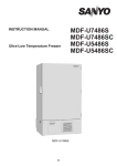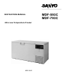
1
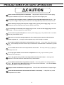
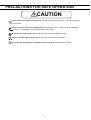
INSTRUCTION MANUAL
Ultra Low Temperature Freezer
MDF-593C
MDF-593C
MDF-793C
Note:
1. No part of this manual may be reproduced in any form without the expressed written
permission of SANYO.
2. The contents of this manual are subject to change without notice.
3. Please contact SANYO if any point in this manual is unclear or if there are any
inaccuracies.
SANYO Electric Biomedical Co., Ltd.
All rights reserved.
Printed in Japan.
CONTENTS
PRECAUTIONS FOR SAFE OPERATION
P. 2
CAUTIONS FOR USAGE
P. 7
ENVIRONMENTAL CONDITIONS
P. 9
FREEZER COMPONENTS
P. 10
INSTALLATION
P. 13
START-UP OF UNIT
P. 15
OPERATING INSTRUCTIONS
P. 16
TEMPERATURE RECORDER
P. 21
ROUTINE MAINTENANCE
P. 25
TROUBLESHOOTING
P. 26
DISPOSAL OF UNIT
P. 27
RECYCLE OF NICKEL-CADMIUM BATTERY
P. 28
SPECIFICATIONS
P. 29
PERFORMANCE
P. 29
SAFETY CHECK SHEET
P. 30
1
PRECAUTIONS FOR SAFE OPERATION
It is imperative that the user complies with this manual as it contains
important safety advice.
Items and procedures are described so that you can use this unit correctly and safely.
If the precautions advised are followed, this will prevent possible injury to the user and
any other person.
Precautions are illustrated in the following way:
WARNING
Failure to observe WARNING signs could result in a hazard to personnel
possibly resulting in serious injury or death.
CAUTION
Failure to observe CAUTION signs could result in injury to personnel and
damage to the unit and associated property.
Symbol shows;
this symbol means caution.
this symbol means an action is prohibited.
this symbol means an instruction must be followed.
Be sure to keep this manual in a place accessible to users of this unit.
< Label on the unit >
This mark is labeled on the cover in which the electrical components of high voltage are
enclosed to prevent the electric shock.
The cover should be removed by a qualified engineer or a service personnel only.
WARNING
As with any equipment that uses CO2 gas, there is a likelihood of oxygen depletion in the vicinity of the
equipment. It is important that you assess the work site to ensure there is suitable and sufficient
ventilation. If restricted ventilation is suspected, then other methods of ensuring a safe environment must
be considered. These may include atmosphere monitoring and warning devices.
2
PRECAUTIONS FOR SAFE OPERATION
WARNING
Do not use the unit outdoors. Current leakage or electric shock may result if the unit is exposed to
rain water.
Only qualified engineers or service personnel should install the unit.
unqualified personnel may cause electric shock or fire.
The installation by
Be sure to install the unit on a sturdy floor. If the floor is not strong enough or the installation site
is not adequate, this may result in injury from the unit falling or tipping over.
Never install the unit in a humid place or a place where it is likely to be splashed by water.
Deterioration of the insulation may result which could cause current leakage or electric shock.
Never install the unit in a flammable or volatile location. This may cause explosion or fire.
Never install the unit where acid or corrosive gases are present as current leakage or electric
shock may result due to corrosion.
Make sure a dedicated power source is used as indicated on the rating label attached to the unit.
Make sure to remove dust from the power supply plug before inserting in a power source. A
dusty plug or improper insertion may cause a hazard.
Use a power supply outlet with ground (earth) to prevent electric shock. If the power supply
outlet is not grounded, it will be necessary to install a ground by qualified engineers.
Never ground the unit through a gas pipe, water main, telephone line or lightning rod. Such
grounding may cause electric shock in the case of an incomplete circuit.
Never store volatile or flammable substances in this unit. This may cause explosion or fire.
Never store corrosive substances in this unit. This may lead to damage to the inner components
or electric parts.
Use this unit in safe area when treating the poison, harmful or radiate articles. Improper use
may cause bad effect on your health or environment.
Always disconnect the power supply to the unit prior to any repair or maintenance of the unit in
order to prevent electric shock or injury.
3
PRECAUTIONS FOR SAFE OPERATION
WARNING
Ensure you do not inhale or consume medication or aerosols from around the unit at the time of
maintenance. These may be harmful to your health.
As with any equipment that uses CO2 gas, there is a likelihood of oxygen depletion in the
vicinity of the equipment. It is important that you assess the work site to ensure there is
suitable and sufficient ventilation. If restricted ventilation is suspected, then other methods
of ensuring a safe environment must be considered. These may include atmosphere
monitoring and warning devices.
Never splash water directly onto the unit as this may cause electric shock or short circuit.
Never disassemble, repair, or modify the unit yourself. Any such work carried out by an
unauthorized person may result in fire or injury due to a malfunction.
Disconnect the power supply plug if there is something wrong with the unit.
abnormal operation may cause electric shock or fire.
Continued
If the unit is to be stored unused in an unsupervised area for an extended period, ensure that
children do not have access and that doors cannot be closed completely.
The disposal of the unit should be accomplished by appropriate personnel. Always remove
doors to prevent accidents such as suffocation.
Make sure to connect a carbon dioxide cylinder or a oxygen gas cylinder to this unit correctly.
Incorrect connection may cause explosion or fire.
Ventilate the room air when using the carbon dioxide gas for the back-up system. The CO2
density level in the air could rise and may be harmful to humans.
Make sure to prepare a safety check sheet when you request any repair or maintenance for the
safety of service personnel.
4
PRECAUTIONS FOR SAFE OPERATION
CAUTION
Select a level and sturdy floor for installation. This precaution will prevent the unit from tipping.
Improper installation may result in water spillage or injury from the unit tipping over.
Connect the unit to a power source as indicated on the rating label attached to the unit. Use
of any other voltage or frequency other than that on the rating label may cause fire or electric shock.
When removing the plug from the power supply outlet, grip the power supply plug, not the cord.
Pulling the cord may result in electric shock or fire by short circuit.
Never damage or break the power supply plug or cord. Do not use the supply plug if its cord
is loose. This may cause fire or electric shock.
Do not touch any electrical parts such as the power supply plug or any switches with a wet hand.
This may cause electric shock.
Make sure to check the setting temperature when starting up the operation after the power
failure or power off. A change of set temperature may cause damage to contents.
Do not put a container with water or heavy articles on the unit. It may cause injury if the articles
fall. Current leakage or electric shock may be resulted form the deterioration of insulation by spilled
water.
Do not climb onto the unit or do not put articles on the unit. This may cause injury by tipping or
damage to the unit.
Do not put glass bottles or cans into the compartment since they may be broken by frozen
contents and cause injury.
Put on dry gloves when you take out refrigerated articles from the freezer.
contents or the inside walls with naked hands may cause frostbite.
Handing frozen
Do not defrost inside walls using a knife or ice pick. There are pipelines for cooling behind the
walls. Be careful not to damage the lines as this could cause a breakdown. Also, do not make a
hole in the wall for installation of attachments.
Always hold the handle when closing the door. This will reduce the likelihood of a trapped finger.
Check the filter mentioned in this manual and clean it as necessary.
temperature rise or failure.
5
A dusty filter may cause
PRECAUTIONS FOR SAFE OPERATION
CAUTION
Do not touch the condenser directly when the filter is removed for cleaning.
by hot surface.
This may cause injury
Always disconnect the power supply plug before moving the unit. Take care not to damage the
power cord. A damaged cord may cause electric shock or fire.
Be careful not to tip over the unit during movement to prevent damage or injury.
Always disconnect the power plug when the unit is not used for long periods.
Do not put the packing plastic bag within reach of children as suffocation may result
6
CAUTIONS FOR USAGE
■ Always use a dedicated power source. The power source of this freezer is single phase and local
voltage. The power source should be the dedicated circuit with a dedicated breaker. Do not connect
this freezer to the branch circuit for other electric appliances.
■ Put on dry gloves when you take out refrigerated articles from the freezer. Handing frozen contents or
the inside walls with naked hands may cause frostbite.
■ For the cleaning of the unit, use a cloth containing diluted neutral dishwashing detergent (Undiluted
detergent may break the plastic parts. For the dilution, follow the instruction enclosed with the
detergent). When a diluted neutral dishwashing detergent is used to clean the unit, wipe the unit
thoroughly with a cloth soaked in clean water. Then wipe the unit with a dry cloth to eliminate the
moisture.
■ Do not clean the unit with scrubbing brushes, acid, thinner, solvents powdered soap, cleanser or hot
water. These agents can scratch the paint or cause it to peel. Plastic and rubber parts can be easily
damaged by these materials. Especially never use any volatile solvent to clean the plastic or rubber
parts.
■ The cooling pipe is routed in the rear of the freezer. Never use a knife or a screw driver, etc. to
remove the frost. They may cause damage of chamber wall or improper operation of the unit. And do
not make any holes for attaching accessories on the freezer wall.
■ The digital thermometer of this unit is designed to display the temperature of the center part of the
freezing compartment. Although the thermometer sometimes display a temperature about 2oC higher
than the actual temperature of the center part, it gradually approaches the real temperature.
■ Do not put too many warm articles into a freezer compartment before enough operating. Put items in
a few at a time after the freezer compartment temperature has cooled enough.
■ The space near the freezer compartment door, about 10 cm from the inner lid, sometimes shows a
higher temperature than the center part. The difference is about 5oC; the lower part may be better for
long term storage.
■ Before operating the freezer, an inner lid should be put in to reduce temperature difference between
top and bottom of the freezing compartment.
■ When it is desired to place an instrument requiring measuring cable and power cord in the cabinet, the
cable and cord can be led through the access port provided on the left side wall on the cabinet. After
installation, replace a rubber cap and insulation as they are. Failure to use a rubber cap or insulation
can interfere with the proper lowering of temperature and lead to condensation on the outside of the port.
7
CAUTIONS FOR USAGE
■ The top surface of the frame sometimes becomes hot during the initial operation or when operating in a
hot environment. This is due to the hot gas circuit for preventing dew, and is not an indication of a
malfunction.
■ This unit is provided with the filter check lamp. If the filter check lamp is flashed, clean the condenser
filter. Refer to page 25 “Cleaning of condenser filter”. A clogged filter may cause poor cooling and
compressor trouble.
■ When connecting a liquid CO2 cylinder for the back-up system , consult your dealer of a neighboring
engineering shop of high pressure gas.
■ Leave the remote alarm switch “OFF” until the inside temperature of the freezer reaches the
appropriate level. Leave the back-up system switch “OFF” as well. After the inside temperature
reaches the appropriate level, set the needle for the warning device operation of the temperature
recorder.
■ When the unit is first installed, or re-started after long period of no use, the power failure alarm may not
operate, because its Cadnica batteries have completely discharged. This does not denote a malfunction.
In this case, continue to operate the unit for about 3 hours. To fully recharge the completely discharged
batteries, the unit has to be operated for about 2 days.
■ Cover the control panel with the control panel cover to avoid the malfunction resulting from an
accidental contact with control panel (such as power switch OFF).
8
ENVIRONMENTAL CONDITIONS
This equipment is designed to be safe at least under the following conditions (based on the IEC 1010-1):
1. Indoor use;
2. Altitude up to 2000 m;
3. Ambient temperature 5oC to 40oC
4. Maximum relative humidity 80% for temperature up to 31oC decreasing linearly to 50% relative
humidity at 40oC;
5. Mains supply voltage fluctuations not to exceed
10% of the nominal voltage;
6. Other supply voltage fluctuations as stated by the manufacturer;
7. Transient over-voltages according to Installation Categories (Over-voltage Categories) II; For mains
supply the minimum and normal category is II;
8. Pollution degree 2 in accordance with IEC 664.
9
FREEZER COMPONENTS
1
2
13
14
3
4
8
5
12
10
11
16
9
6
15
7
MDF-593C
10
FREEZER COMPONENTS
1. Lock
2. Door: Hinged type. The door can be opened in any angle on the way to full open.
3. Magnetic door gasket:
Seals the door and prevents leakage of cold air.
4. Inner lid: Serves as a means of reducing cold air leakage when the door is open. Remove the frost
before it is accumulated too much.
5. Access port: Serves a means of leading the measuring cable from the freezing room to the outside.
6. Caster:
4 casters are provided. They make the moving of the unit easier.
7. Leveling foot: Serves to adjust the height and to settle the frame.
8. Temperature display area: The digital temperature indicator, alarm lamp, and filter check lamp are
installed.
9. Exhaust air vent: Be careful not to block this.
10. Control panel cover
11. Control panel cover lock:
contact.
12. Control panel:
details.
To lock the control panel cover to avoid the setting by accidental
Temperature set key, power switch and so on are installed. Refer to page 12 for
13. Back-up system joint (rear side): It is positioned at rear of the unit. Serves to connect with the
pipelines from the liquid CO2 cylinder.
14. Side panel: For cleaning the condenser filter and condenser.
inside the panel.
The remote alarm terminal is located
15. Air intake vent (grille): Do not block this vent to keep the proper cooling performance.
16.
11
FREEZER COMPONENTS
Control panel
10 12 11 9
1
5
6
2 3
7
8
4
1. Power switch (POWER): Power all functions except remote alarm and back-up system for AT type.
2. CO2 Back-up switch (CO2 BACK UP):
MDF-593C is not equipped.
MDF-793C is not equipped.
3. CO2 Back-up test switch (TEST):
MDF-593C is not equipped.
MDF-793C is not equipped.
4. Remote alarm switch (REMOTE ALARM):
remote alarm, turn the switch to “ON”.
This switch is for remote alarm. In case of operating
5. Temperature setting key. (PV/SV): This key has functions.
PV: Present freezer compartment temperature is displayed.
SV: Setting temperature is displayed. When the desired temperature is set, this key should be
passed (SV side). The temperature setting can be done by using (6),(7),(8), keys, initial setting
temperature is -85oC.
6. Digit shift key (
using this key.
7. Figure shift key (
): The digital of the figure displayed for temperature adjustment can be shifted
): The figure that is displayed digitally can be changed by pressing this key.
8. Enter key (ENT): When the desired temperature is reached, press this key.
commence toward this new point.
9. Alarm test key (ALARM):
deep-freezer is operating well.
Check that the alarm lamp and the buzzer are functional when the
10. Buzzer key (BUZZER): To stop the alarm from sounding, press this key.
abnormality occur, the buzzer will sound automatically.
11. Alarm lamp (ALARM) and buzzer:
a)
Operation will
Should a further
they operate in the following cases:
Break down or power failure at the power supply.
- Alarm lamp flickering, buzzer sounds.
b)
Temperature rises about 10oC higher than the setting temperature.
- Alarm lamp flickering, buzzer sounds about 15 minutes later.
12. Filter check lamp (FILTER CHECK):
This lamp lights when the condenser filter is clogged.
12
Clean the condenser filter according to page 25 “Cleaning of condenser filter”.
INSTALLATION
Installation site
To operate this unit properly and to obtain maximum performance, install the unit in a location with the
following conditions:
■ A location not subjected to direct sunlight
The direct sunlight to the freezer causes too high temperature and the chamber temperature may not
reach -85oC.
■ A location with adequate ventilation
Leave at least 10 cm around the unit for ventilation. Poor ventilation will result in a reduction of the
refrigeration capacity.
■ A location away from heat generating sources
Avoid installing the unit near heat-emitting appliances such as gas ranges or stoves. Heat can cause
inefficient refrigeration.
■ A location with a sturdy and level floor
Install the unit on a sturdy floor to avoid vibration and noise. Placing the unit on an unsteady floor may
cause vibration and noise.
■ A location not prone to high humidity
WARNING
Install the unit on a sturdy floor. If the floor is not strong enough or the installation site is not
adequate, this may result in injury from the unit falling or tipping over.
Select a level and sturdy floor for installation. This precaution will prevent the unit from tipping.
Improper installation may result in water spillage or injury from the unit tipping over.
■ A location not prone to high humidity
WARNING
Do not use the unit outdoors. Current leakage or electric shock may result if the unit is exposed to
rain water.
Never install the unit in a humid place or a place where it is likely to be splashed by water.
Deterioration of the insulation may result which could cause current leakage or electric shock.
■ A location without flammable or corrosive gas
WARNING
Never install the unit in a flammable or volatile location. This may cause explosion or fire.
Never install the unit where acid or corrosive gases are present as current leakage or electric shock
may result due to corrosion.
13
INSTALLATION
Installation
1. Remove the packaging materials and tapes
Remove all transportation packaging materials and tapes. Open the doors and ventilate the unit. If
the outside panels are dirty, clean them with a diluted neutral dishwashing detergent. (Undiluted
detergent can damage the plastic components. For the dilution, refer to the instruction of the
detergent.) After the cleaning with the diluted detergent, always wipe it off with a wet cloth. Then
wipe off the panels with a dry cloth.
2. Adjust the leveling foot
Extend the leveling feet by rotating them
counterclockwise to contact them to the floor.
Ensure the unit is level.
Leveling foot
3. Fix the unit
Two fixtures are attached to the rear of the frame. Fix the frame to the wall with these fixtures and
rope or chain.
If holes can be opened on the wall, open a hole with a 10.5mm diameter and fix the frame by using the
special bolt-nut supplied with this unit. This bolt-nut can be used only on concrete walls.
4. Ground (earth)
WARNING
Use a power supply outlet with ground (earth) to prevent electric shock. If the power supply outlet
is not grounded, it is necessary to install a ground by qualified engineers.
Never ground the unit through a gas pipe, water main, telephone line or lightning rod. Such
grounding may cause electric shock in the case of an incomplete circuit.
14
START-UP OF UNIT
Follow the procedures for the initial and consequent operations of the unit.
1. Make sure that all the switches on the control panel, such as the power switch, the remote alarm
switch, the back-up system switch are off.
2. Liquid CO2 gas cylinder is set at this time.
3. Shut the door and connect the power cable to the power supply after the inner lid is installed.
4. Turn on the power supply switch and the temperature is displayed on the digital indicator.
5. Set the desired chamber temperature by using the keypads on the control panel. Do not set the
chamber temperature at lower than -90oC.
6. Set the temperature at which the back-up system activates according to the procedure on page 21
when the temperature display pointer of temperature recorder corresponds with the desired temperature
if the back-up system is used.
7. Switch on the remote alarm switch and back-up system switch.
8. Check that the alarm lamp lights and the buzzer sound by pressing the alarm test key.
9. Make sure that liquid CO2 spouts into the chamber by pushing the back-up test switch.
10. Now you can put articles into the freezer chamber. Switch off the remote alarm switch and the
back-up system switch temporarily when putting in a lot of warm articles. Switch on these switches
again after a certain period of operation.
Operation after power failure
The set value is memorized by nonvolatile memory in the event of power failure.
freezer resumes the operation with setting before power failure.
15
Accordingly, the
OPERATING INSTRUCTIONS
Temperature setting
Table 1 shows the basic operation method. Perform key operations in the sequence indicated in the
table. The example in the table is based on the assumption that the temperature is -70oC.
Note: The unit is set at the factory that the chamber temperature is -85C.
Table 1.
Chamber temperature -70oC)
Basic operation sequence (Example:
Description of operation
1 Turn on the power switch.
Press mode change key when
1 changing the set temperature
during operation.
Key operated
Indication after operation
The current chamber temperature is
displayed.
-----
PV/SV
The second digits blinks.
2
Set the second digit to 7 with the
numerical value shift key.
When pressed, the figure of settable
digit changes.
3
By pressing the digit shift key, set
the first digit.
The first digit blinks.
4
Set the first digit to 0 with the
numerical value shift key.
When pressed, the figure of settable
digit changes.
5 Press enter key.
ENT
Set temperature is memorized and
the current chamber temperature
is displayed.
Note: The temperature set mode returns to the temperature display mode automatically when 90
seconds has passed without any key operation.
Remote alarm terminal
The terminal of the remote alarm is located at rear of the machinery room, upper side of the electric box.
The signal is contact output. The recommended contact capacity is between 2 A (DC 30V) .
Contact output: : normal close connect with N.O. and COM.
Consult our dealer or our office for installation of the remote alarm.
16
OPERATING INSTRUCTIONS
Alarm temperature setting
This unit is provided with the high temperature alarm. The setting of high temperature alarm is 10oC or
15oC higher than the setting of chamber temperature. The procedure in table 2 shows the sequence to
set the high temperature alarm at 15oC higher than the setting of chamber temperature. Set the figure to
000 at step 5 when setting the high temperature alarm at 10oC higher than the setting of chamber
temperature.
Note:
The alarm temperature is set at the factory 10oC higher than the setting of chamber temperature.
Table 2.
High temperature alarm setting (15oC higher than the setting of chamber temperature)
Description of operation
1
Key operated
-----
Indication after operation
The current chamber temperature is
displayed.
2
Press the numerical value shift key
for about 5 seconds.
The first digit blinks.
3
Set the first digit to 1 with the
numerical value shift key.
The first digit blinks.
4 Press ENT key.
5
ENT
Set the first digit to 1 with the
numerical value shift key.
6 Press ENT key.
The first digit blinks.
When pressed, the figure of settable
digit changes.
ENT
Alarm temperature is memorized and
the current chamber temperature
is displayed.
Note: The setting is not memorized if the mode change key (PV/SV) is pressed during alarm
temperature setting. The chamber temperature is displayed for 3 seconds when the numerical value
shift is pressed 5 times continuously.
17
OPERATING INSTRUCTIONS
Setting of alarm resume time
The alarm buzzer is silenced by pressing BUZZER key on the control panel during alarm condition (Initial
setting 100: The remote alarm is not silenced).
The buzzer will be activated again after certain suspension if the alarm condition is continued. The
suspension time can be set by following the procedure shown in the Table 3 below.
The example in the table is based on the assumption that the desired duration is 30 minutes.
Note: The duration is set to 100 (no alarm resume time) at the factory.
Table 3.
Setting procedure (change to 30 minutes from no alarm resume time)
Description of operation
1
2
Key operated
-----
Press the numerical value shift key
for about 5 seconds.
The settable digit is shifted.
When pressed, the figure of settable
digit changes.
ENT
The current setting is displayed
and the first digit blinks.
The settable digit is shifted.
Set to 130 with the digit shift key
5
and numerical value shift key.
6 Press ENT key.
The current chamber temperature is
displayed.
The first digit blinks.
Set to F25 with the digit shift key
3
and numerical value shift key.
4 Press ENT key.
Indication after operation
When pressed, the figure of settable
digit changes.
ENT
Alarm resume time is memorized
and the current chamber
temperature is displayed.
• The settable alarm resume time is between 10 and 60 minutes with 1 minute increment. (The setting is
010, 111, ------- 159, 160). The buzzer would not reset if the resume time is set in 000.
• The buzzer is ON when the resume time is changed in F25 while the resume time is counted (the
buzzer is silenced by BUZZER key). The count of resume time is stopped.
• The setting cannot be changed during power failure.
• The set mode returns to the temperature display mode automatically when 90 seconds has passed
without any key operation. In this case, any setting before pressing ENT key is not memorized.
• It is selectable whether the buzzer is in conjunction with the remote alarm or not when the buzzer is
silenced by BUZZER key. (The remote alarm is not in conjunction with the buzzer by factory setting.)
• The remote alarm is activated in conjunction with the buzzer if the third digit “1” is set to “0” in the step 5
above
18
OPERATING INSTRUCTIONS
Alarm and safety functions
This unit has the alarm and safety functions shown in table below, and also self diagnostic function.
Table 4.
Alarm and safety function
Alarm & safety
Situation
High temperature
alarm
When the chamber temp. is
approx. 10oC (or 15oC) higher
than the set temp.
Power failure
alarm
Filter check
Auto-return
At power failure
When power cord is
disconnected.
When the condenser filter
is clogged.
When there is no key
pressing in each setting
mode for 90 seconds.
If the thermal sensor is
disconnected.
If the thermal sensor is
shirt-circuited.
Sensor
abnormality
If the cascade sensor is
disconnected.
If the cascade sensor is
shirt-circuited.
If the filter sensor is
disconnected.
If the filter sensor is
short-circuited.
Indication
Alarm lamp blinks.
Alarm lamp blinks.
Buzzer
Safety operation
Intermittent
tone
with Remote alarm
12
with 12 min. delay
min. delay
Intermittent
tone
Filter check lamp lights.
-----
Chamber temp. is
displayed.
-----
Alarm lamp blinks.
E01 and 50oC is
displayed alternately.
Alarm lamp blinks.
E01 and -170oC is
displayed alternately.
Alarm lamp blinks.
E03 and chamber temp.
is displayed alternately.
Alarm lamp blinks.
E04 and chamber temp.
is displayed alternately.
Alarm lamp blinks.
E05 and chamber temp.
is displayed alternately.
Alarm lamp blinks.
E06 and chamber temp.
is displayed alternately.
Remote alarm
----Finishing of each
setting mode
Intermittent
tone
Remote alarm
Continuous
operation
Intermittent
tone
Remote alarm
Intermittent
tone
Remote alarm
Note
The filter check lamp sometimes lights at the start-up under high ambient temperature. The lamp will is
off when the chamber temperature is getting lower.
Operation after power failure
The set value (setting of chamber temperature and alarm temperature) is memorized by nonvolatile
memory. Accordingly, the freezer resumes the operation with setting before power failure.
19
OPERATING INSTRUCTIONS
Back-up system
WARNING
As with any equipment that uses CO2 gas, there is a likelihood of oxygen depletion in the vicinity
of the equipment. It is important that you assess the work site to endure there is suitable and
sufficient ventilation. If restricted ventilation is suspected, then other methods of ensuring a
safe environment must be considered. These may include atmosphere monitoring and warning
devices.
The freezer is provided with an automatic liquid CO2 gas injection device as a back-up system. This
freezer prevents the chamber temperature from going up by injecting the liquid CO2 gas when the power
supply is disconnected (power failure, disconnection of power cord, breaker OFF) or in the case of failure
of freezer itself. The liquid CO2 gas is injected with the activation of solenoid valve energized by battery
when the chamber temperature reaches the alarm temperature.
Following shows the procedure for setting the back-up system.
1. Setting of liquid CO2 gas cylinder
By using the joint and pipe enclosed with the
freezer, connect the liquid CO2 gas cylinder to the
joint of the back-up system. For this setting,
consult with a qualified gas supplier or Sanyo sales
agency.
Liquid CO2
gas cylinder
Battery
2. After setting the liquid CO2 gas cylinder, operate
the freezer until the chamber temperature reaches
the required level.
Solenoid valve
Pipe
3. Set the warning indicator of the recorder at the
temperature higher than -70oC. The back-up
system is operated continuously if the warning
indicator is set at the temperature lower than -70oC.
This means the liquid CO2 gas is consumed very
quickly.
4. Switch on the back-up system.
5. Make sure that liquid CO2 gas spouts into the freezer chamber by pressing the back-up test switch.
Note:
• The liquid CO2 gas cylinder loses its cooling capacity at speed when the ambient temperature is over
31oC. Install the liquid CO2 gas cylinder in the cool environment. And the duration of back-up time per
one liquid CO2 gas cylinder varies depending on the ambient temperature. Refer to “Installation of
back-up system” enclosed with the freezer for the available back-up time.
• The liquid CO2 gas cylinder should be a siphon type.
• Use the pipe encloses with the freezer for the setting. (The extension of the pipe is not permitted
because of cooling capacity.)
20
TEMPERATURE RECORDER
The figure below shows the description of a temperature recorder.
Time
Temperature
Warning indicator
Recording indicator
Pen holder lever
Door
Cartridge
Feeding of chart
1. Open the door and let down the lever of the penholder; the pen point is apart from the chart. (Fig. 1)
2. Pull the cartridge out of the mounted position. (Fig. 2)
3. Set a new chart in place on the rear bottom of the cartridge. Set the hole on the chart in the cog of the
chart driving assembly and feed the chart in the direction of the arrow by driving the cog wheel.
4. Set the chart according to the mark of day and time. (Fig. 3)
5. When mounting, lay down the cartridge first, and push into the mounting position with the groove set a
the projection on the position.
6. Set up the cartridge and settle in position.
Fig. 2
Fig. 1
Fig. 3
Replacement of cell
Replace the dry cell once a year as follows:
1. Put up the penholder first, then pull out cartridge
from the mounted position.
2. Reset the battery chamber cover with wire, on the
bottom left side, and take out the cell.
3. Set a new cell by turning its anode to this side.
4. Shut the cover after exchanging cells. Mount the
cartridge as before and lay down the penholder.
Cell
21
TEMPERATURE RECORDER
Setting of back-up temperature
1. There is a red guide on the top of the temperature displayer. Adjust the guide with your finger to
back-up temperature, at which temperature the auxiliary cooling system starts to operate.
2. Set at a temperature 15oC higher than that of the freezer compartment.
Penholder
Install a recording pen in the recording hand as
shown in the figure. Make sure that the pen is
completely inserted for accurate recording. The
pen is packed together with the chart.
1. Let down the lever of the penholder, then pull out
the cartridge from the mounted position.
2. Insert a new pen.
3. Mount the cartridge into place.
4. Lift up the penholder lever and make sure that the
pen point touches the chart.
Note:
■ Turn off the back-up switch when the freezer operation is stopped or the back-up system is not used.
The battery for back-up system is discharged when the back-up switch is kept on.
■ The additional felt pen or recording paper is available from Sanyo sales agency.
■ To stop the temperature recorder, remove the cell from the recorder. The back-up system can
operate without recorder cell. Always remove a felt pen as well because the recording paper can be torn
resulting from ink spot. The torn paper may interfere pen tip movement, which results in no activation of
back-up system.
■ The cell for recorder normally keeps about 1 year. However, the cell life is shorten depending on the
ambient temperature condition. The enclosed cell may have shorter life since it is for monitor.
■ The liquid leakage or rust can be caused when a used cell or a cell over effective limit is left as it is,
which gives adverse effect on the recorder.
22
TEMPERATURE RECORDER
When a 7day circular type recorder is installed, a slip chart recorder can not be attached.
Follow the procedure bellow to attach a 7day circular chart recorder to the freezer.
NOTE: Only a specified recorder is applicable to the freezer. For the selection of an applicable recorder,
please consult with a sales shop
1. Make sure that all the switches including power supply are turned
off.
2. Remove the side cover by loosening four screws. (Fig.1)
3. After removing a grille screw, open the grille as shown in Fig. 1.
4. Remove the control panel by loosening two screws on the lower
outside (A) and upper inside (B) of the control panel. (Fig. 1)
5. Detach the cover on the control panel by removing four screws.
Fig. 1
(Fig. 1)
Control Panel
6. As shown in Fig.2, secure the temperature recorder to the control
panel using with the fixing kit.
7DAY CIRCULAR
CHART RECORDER
Fig. 2
7. Replace the control panel with the recorder attached and fix the
panel with screws. (Fig. 3)
Fig. 3
23
TEMPERATURE RECORDER
8. Remove the sensor cover at the rear of the chamber wall. (Fig.
4)
Fig. 4
9. Pass through the hole under the temperature control sensor. (Fig.
5)
Tool for the hole:
Screw driver
(example)
Hole depth:
135mm (5.3inch) Hole diameter: 13mm (0.5inch)
10. Route the recorder sensor into the chamber by sassing the hole.
(Fig. 4)
Fig. 5
11. Remove the sensor support and position the recorder sensor and
then replace the stopper. (Fig. 4)
12. Seal around the hole for recorder sensor completely by applying
the sealing compound (RTV) to outside and inside of the chamber.
(Fig. 4)
13. Connect the power cord of the recorder to the terminal as shown
in Fig. 6.
N
Neutral
L
Live
E
Earth
14. Fix the grille with a screw and replace the side cover.
24
Fig. 6
ROUTINE MAINTENANCE
WARNING
Always disconnect the power supply to the unit prior to any repair or maintenance of the unit in
order to prevent electric shock or injury.
Ensure you do not inhale or consume medication or aerosols from around the unit at the time of
maintenance. These may be harmful to your health.
Cleaning
1. Clean the unit once a month. Regular cleaning keeps the unit looking new.
2. Use a dry cloth to wipe off small amounts of dirt on the outside and inside of the unit and all
accessories. If the unit is very dirty, use a neutral detergent.
3. After cleaning, wipe away the cleaner completely with a cloth washed in clean water.
4. Never pour water onto or into the unit. Doing so can damage the electric shock or short circuit.
5. The compressor and other mechanical part are completely sealed. This unit requires absolutely no
lubrication. There is a fan behind the compressor, so be very careful if you stick your hand into this part
of the unit.
Cleaning of condenser filter
This unit is provided with the filter check lamp. This lamp
flickers and the buzzer sounds when the condenser filter is
clogged. Clean the filter according to the following
procedure. As a clogged filter may cause poor cooling
and compressor trouble, clean it once a month.
1. The filter fitted to the grille can be removed as shown in
the figure.
2. Remove the mounting screw securing the grille and pull
out the grille.
3. Remove the filter installed inside the grille, wash it with
water and dry it naturally.
4. Replace the clean filter as before.
5. Replace the grille and tighten the screw and check that
the filter check lamp is off.
Defrosting of inside wall
Defrost the inside wall of the freezer as follows:
Normal defrosting
Remove the frost by the enclosed scraper.
Take care not to damage the inside wall.
Thorough defrosting
1. Take out and transfer all the contents to another freezer or container which contains liquid CO2, liquid
N2, or dry ice. Switch off the alarm and back-up system of AT type. Switch off the power supply.
2. Open the door and remove the inner lid. Leave the freezer as it is. The water remaining in the
freezer compartment should be wiped up.
3. After cleaning is completed, restart the operation according to the procedure. Put back the articles
into the sufficiently cooled freezer compartment.
25
TROUBLE SHOOTING
If the unit malfunctions, check out the following before calling for service, after transferring all the contents
to another freezer
No refrigeration
■ The voltage is too low. (In this case, call an electrician.)
■ The breaker is free.
■ The fuse is blown.
Sometimes the freezer is not cooled at all for about 5 minutes after starting-up.
Poor refrigeration
■ The ambient temperature is too high.
■ The door is not shut tightly.
■ The inner lid is not installed correctly.
■ The set temperature in the controller is not set properly.
■ The grille is blocked out.
■ The filter is clogged. Clean the filter when the filter check lamp lights.
■ The freezer is in the direct sunlight.
■ There is any heating source near the freezer.
■ A rubber cap and insulation for the access port are not set correctly.
■ You put too many unfrozen articles into the freezer compartment.
■ Too much frost is accumulated in the chamber.
Noise
■ The freezer is not installed on the sturdy floor.
■ There is anything touching the frame.
■ The freezer is not leveled with the leveling feet.
■ It is the immediately after starting of refrigeration.
The freezer causes larger noise when the chamber temperature is high because of large load. The
noise gets smaller along with chamber temperature.
Alarm test key cannot actuate the alarm function
■ The alarm test key does not function when the power switch of the freezer is OFF.
■ When only the buzzer or only the alarm is actuated by the alarm test key, the unactuated part is out of
order, and must be replaced.
Recorder does not operate normally (AT type only)
■ If the chart is not advanced, examine the dry cell. Replace the cell for recorder every 1 year.
■ If the temperature is not recorded, examine the recording pen. The pen should be our specified one.
Back-up test switch does not operate normally (AT type only)
■ The liquid CO2 cylinder is empty.
■ The valve of the liquid CO2 cylinder is not opened.
■ The ambient temperature is too high. In this case, move the liquid CO2 cylinder to a cool location.
Inquire at liquid CO2 suppliers about cylinder check, adjustment, installation, or move.
26
DISPOSAL OF UNIT
WARNING
If the unit is to be stored unused in an unsupervised area for an extended period ensure that children
do not have access and doors cannot be closed completely.
The disposal of the unit should be accomplished by appropriate personnel. Always remove
doors to prevent accidents such as suffocation.
27
RECYCLE OF NICKEL-CADMIUM BATTERY
The unit contains a rechargeable battery. The battery is recyclable. At the end
of it’s useful life, check with you local solid officials option or proper disposal.
Label indication is obliged to comply with Taiwanese battery regulation.
Location of a nickel-cadmium battery
This unit is provided a nickel-cadmium battery for the power failure alarm. The battery is located in the
control box behind the control panel.
Removal of nickel-cadmium battery
1. Turn off the power switch and disconnect the power supply plug.
2. As shown in the Fig. 1, remove 4 fixing screws on the front panel and remove the front panel.
3. Remove 4 fixing screws on the control panel and take out the control panel. (Fig. 2)
4. Remove 2 fixing screws on the control box to remove the control box cover. (Fig. 3)
5. Remove 2 screw fixing the clips securing the battery and then disconnect the connector. (Fig. 4)
Handling of battery
Cover the battery terminal with an insulating tape to avoid the short circuit. Then follow the procedure
for recycling or proper disposal.
Control box
Side Cover
Fig. 1
Fig. 2
Battery
Control box
Clip
Connecter
Fig. 3
28
Fig. 4
SPECIFICATIONS
Name
Ultra-Low Temperature Freezer
Model
MDF-593C
MDF-793C
External dimensions
W2010 x D770 x H1070 (mm)
W2570 x D770 x H1070 (mm)
Internal dimensions
W1280 x D500x H762 (mm)
W1840 x D500x H762 (mm)
487 L
701 L
Effective capacity
Exterior
Baked on acrylic finish on galvanized steel
Interior
Stainless steel
Door
Baked on acrylic finish on galvanized steel
Insulation
Rigid polyurethane foamed-in place
Compressor
Motor for compressor
Hermetic type
Condenser
High stage side; 750 W
High stage side; 1100 W
Low stage side; 750 W
Low stage side; 1100 W
High stage side; fin and tube type, Low stage side; shell and tube type
Evaporator
Tube on sheet type
Refrigerant
High stage side; R-407D , Low stage side; R-508 (TP5R3)
Power source
Temperature controller
AC 200 V, 60 Hz
Microprocessor control system, Setting range; -20 to -95oC, 1oC graduation
Digital display (+50 to -100oC)
Temperature display
Pt 100
Sensor
Alarm
Nickel-cadmium battery, Remote alarm contact, Buzzer and lamp
Battery
For power failure alarm; 6VDC, 270mAh
Voltage booster
Accessories
Electrical; 208/230 V, 1 HP, 60 Hz
Minimum operating voltage; 193 V at start-up of compressor
1 set of key, 2 rubber caps, 1 scraper
Weight
319 kg
Option
Note
380 kg
Aluminum container; MDF-59SC, Inventory rack; IR213C, IR309C
Temperature recorder; MTR-85H, CVK-UB2
Design or specifications will be subject to change without notice.
The battery for power failure alarm is an article for consumption. It is recommended that the battery
will be replaced about every 3 years. Contact Sanyo sales agency at the time of replacement of the
battery for recycling.
PERFORMANCE
Model
MDF-593C
Cooling performance
-20 to -85oC
Temperature Control range
Power source
Rated power consumption
Noise level
Maximum pressure
Note
MDF-793C
Center part of freezing room; -86oC (Ambient temperature; +30oC, no load)
AC 200V, 60Hz
1100 W
1240 W
61 dB [A] (background noise; 20 dB)
1.9 Mpa
2.1 MPa
The unit with CE mark complies with EC directives 89/336/EEC, 93/68/EEC and 73/23/EEC
29
CAUTION
Please fill in this form before servicing.
Hand over this form to the service engineer to keep for his and your
safety.
Safety check sheet
1. Refrigerator contents :
Risk of infection:
Risk of toxicity:
Risk from radioactive sources:
Yes
No
Yes
Yes
Yes
No
No
No
(List all potentially hazardous materials that have been stored in this unit.)
Notes :
2. Contamination of the unit
Unit interior
No contamination
Decontaminated
Contaminated
Others:
Yes
No
Yes
Yes
Yes
No
No
No
3. Instructions for safe repair/maintenance of the unit
a) The unit is safe to work on
Yes
No
b) There is some danger (see below)
Yes
No
Procedure to be adhered to in order to reduce safety risk indicated in b) below.
Date :
Signature :
Address, Division :
Telephone :
Product name:
Ultra-low temperature
freezer
Model:
Serial number:
MDF-
Please decontaminate the unit yourself before calling the service engineer.
30
Date of installation:
7FB6P10140700
SANYO Electric Biomedical Co., Ltd.
(22 Feb. 2005)
Recycled paper
CEM
10-15, Hongo 3-Chome
Bunkyoku, Tokyo 113-8434 Japan
Printed in Japan