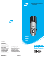
1
■ Before attempting to operate this product, please read
the instructions carefully.
•ENGLISH
•ESPAÑOL
•日本語
SALES NETWORK
SAMSUNG TECHWIN CO., LTD.
145-3, Sangdaewon 1-dong, Jungwon-gu,
Seongnam-si, Gyeonggi-do 462-703, Korea
Tel : +82-31-740-8137~8141 Fax : +82-31-740-8145
SAMSUNG OPTO-ELECTRONICS AMERICA, INC.
ELECTORONIC IMAGING DIV.
40 Seaview Drive, Secaucus, NJ 07094, U.S.A
Tel : +1-201-902-0347 Fax : +1-201-902-0429
SAMSUNG TECHWIN MOSCOW OFFICE
Korp 14, 37-A, PR-KT, Lenningradsky,
Moscow 125167, Russia
Tel : +7-95-258-9296, 9298 Fax : +7-95-258-9297
http://www.samsungtechwin.com
http://www.samsungcctv.com
SAMSUNG OPTO-ELECTRONICS UK LTD.
Samsung House, 1000 Hillswood Drive,
Hillswood Business Park Chertsey, Surrey KT16 OPS
Tel : +44-1932-45-5308 Fax : +44-1932-45-5325
TIANJIN SAMSUNG OPTO-ELECTRONICS CO., LTD .
7 Pingchang Rd., Nankai Dist. Tianjin 300190, P.R China
Tel : +86-22-2761-4724(33821) Fax : +86-22-2761-6514
P/No.:6806-0575-01A
Operation/Programming
ENGLISH
Thank you for purchasing a SAMSUNG CCTV CAMERA.
Before operating the camera, confirm the camera model and proper
input power voltage. In order that you can understand this manual
thoroughly, we'll introduce our model description.
Model Description
SPD-2200 x
Signal System
• Signal System
N
NTSC Model
P
PAL Model
The lightning flash with an arrowhead symbol, within an equilateral
triangle is intended to alert the user to the presence of uninsulated
“dangerous voltage” within the product's enclosure that may be of
sufficient magnitude to constitute a risk of electric shock to persons.
The exclamation point within an equilateral triangle is intended to alert the
user to the presence of important operating and maintenance (servicing)
instructions in the literature accompanying the appliance.
INFORMATION -This equipment has been tested and found to comply with
limits for a Class A digital device, pursuant to part 15 of the FCC Rules.
These limits are designed to provide reasonable protection against harmful
interference when the equipment is operated in a commercial environment.
This equipment generates, uses, and can radiate radio frequency energy
and, if not installed and used in accordance with the instruction manual, may
cause harmful interference to radio communications.
Operation of this equipment in a residential area is likely to cause harmful
interference in which case the user will be required to correct the
interference at his own expense.
WARNING - Changes or modifications not expressly approved by the
manufacturer could void the user’s authority to operate the equipment.
CAUTION : To prevent electric shock and risk of fire hazards:
Do NOT use power sources other than that specified.
Do NOT expose this appliance to rain or moisture.
This installation should be made by a qualified service person
and should conform to all local codes.
2
SPEED DOME CAMERA
SPEED DOME CAMERA
3
Contents
Camera settings ...................................................................................... 26
Main Features ........................................................................................... 9
OSD Menu Configuration .............................................................. 26
Components ............................................................................................ 10
Front Panel ................................................................................... 10
Back Panel .....................................................................................11
Dome Camera User’s Menu Setting ............................................ 28
Camera Setting ............................................................................. 28
Sequence Setting ......................................................................... 35
P/T Setting .................................................................................... 40
Getting started ......................................................................................... 12
Bracket Setup for Installation .........................................................12
Initial Setting ..................................................................................13
Accessories ....................................................................................19
How to Install ........................................................................................... 20
OSD Setting ................................................................................. 44
Alarm Setting ............................................................................... 47
Initialize Setting ............................................................................. 50
Status ............................................................................................ 51
Product Appearance and Installation Method ......................................... 52
Cable ..............................................................................................20
Accessories (option) .......................................................................22
How to Install Camera ....................................................................24
4
SPEED DOME CAMERA
System configuration................................................................................ 53
Specifications .......................................................................................... 55
SPEED DOME CAMERA
5
ENGLISH
Warning & Caution .................................................................................... 6
Warning & Caution
The unit should be installed by trained
personnel.
Always stop using the product if it emits smoke
or becomes unusually hot.
Warning / Caution
Warning
If you fail to read this information, or handle the product
incorrectly, death or serious injury may result.
Caution
If you fail to read this information, or handle the product
incorrectly, serious injury or physical damage may result.
Installation by unskilled personnel without sufficient experience or
expertise may result in fire or electric shock. Always ask your sales
agent to perform installation.
Never install the product in areas exposed to
water, oil or gas.
Continuing to use it under such circumstances may result in fire.
Never install the product on a ceiling that Is not
strong enough to bear its weight.
Sign
Doing so may result in malfunctions, electric shock or fire.
Not allowed.
Never touch the power cord with wet hands.
The product may fall.
Never disassemble the product or insert foreign
bodies into it.
No disassembly.
Be sure to keep this.
Touching the power cord with wet hands may result in electric shock.
6
SPEED DOME CAMERA
Malfunction may result.
SPEED DOME CAMERA
7
ENGLISH
Please read the instructions carefully for correct use of the product, and observe these
cautions to prevent danger or physical damage while operating it.
Warning
Caution
Never install the product in places where the
lighting conditions fluctuate.
Auto-focusing 22x Zoom lens
Day & Night function
The digital zoom function of the built-in 22x zoom
lens, together with its auto-focus feature, zooms
an image by up to 220x.
Slow-shutter and day and night switching enable
optimum screen monitoring over 24 hours.
Various auto-surveillance functions
Installing the product in areas subject to temperatures of over 50°C
or below 0°C may result in deterioration of picture quality or other
problems. Pay special attention to ventilation when installing the
product in high ambient temperatures.
Never drop the product, or subject it to severe
impact or vibration.
Frequent changes of illumination, for example from unstable
fluorescent lighting, may result in malfunction.
Never expose the product to direct sunlight or
harmful rays.
·PTZ trace
Manually plays recorded images of up to about
120 seconds.
·Auto swing
Repeats pan and tilt between two preset
positions.
·Group sequence
Switches to and checks a maximum of 128
preset positions in order.
·Tour sequence
Switches to and checks a maximum of 6 group
sequences in order.
Malfunction may result.
Never touch the glass on the front of the
product.
This glass is one of the key components.
Be careful not to leave fingerprints or other marks on the glass.
8
SPEED DOME CAMERA
Direct sunlight or harmful rays may cause fatal damage to the CCD
or internal circuitry.
Never install the product in areas exposed to
rain or water.
If water gets into the product it may cause failure.
Smart P/T function
Pan and tilt speed compensation function linked
to zoom position allows fine manual operation
even during zooming.
✽Slow-shutter function improves CCD sensitivity
by electrically lengthening exposure time.
✽Day & Night function enables the color and
black and white screens to be used respectively
during the day and at night.
OSD (On Screen Display) function
Provides character information displayed on the
monitor, such as the camera ID address, camera
name, preset number, preset name, area name
and sequence status, and easily sets various
camera functions from the OSD menu screen.
Home Position Auto Return function
Returns the dome to a specified preset position
at a fixed time after ending manual operation.
128 Preset Positions
A maximum of 128 preset positions can be set.
The preset function enables you to set the
location you want to monitor at any time.
Area Masking for 8 points
Auto Flip
Area Masking can be set up for up to 8 points.
For Privacy, this device provides a function for
hiding the points for which Area Masking is
selected from the screen.
For monitoring an object moving below a
camera, run Auto Flip using a joystick controller,
and moving objects can be monitored without
reversing, both up and down and left to right.
SPEED DOME CAMERA
9
ENGLISH
Never install the product in locations with
extreme high or low temperature.
Main Features
Components
ENGLISH
Front Panel
Back Panel
Connector Cable
Connect to the bracket
connector for installation.
Power Switch
Rotary Switch 2 (SW2)
Power on or off
(※Factory default : OFF)
Camera ID address setting
switch.
Protocol Selection Switch
Rotary Switch 1 (SW1)
Camera ID address setting
switch.
Controller In Terminal
DIP Switch (SW3)
For setting each function
1. For selecting a controller
2. For factory setting
3. For terminal setting
4. For terminal setting
Video Out Terminal
ALARM Out
AC 24V Out
Cautions
·If the Rotary Switch and DIP Switch (SW3) are not displayed, turn the power off and on again. Both switches will then be
displayed.
·Do not pull or hold onto the connector cables when moving or delivering the product. It may cause operational failure.
·See the inside of the door for settings for the switches on the main unit of the product.
10
SPEED DOME CAMERA
Power LED
ALARM In
Power In Terminal
SPEED DOME CAMERA
11
Getting started
Initial Setting
ENGLISH
Bracket Setup for Installation
Video Out
Alarm In 1
Alarm In 2
● Communication Protocol Setting (Installation Bracket)
Select and set SW1 on the installation bracket for setting the communication protocol.
Alarm In 3
Alarm In 4
Alarm Out 1
Alarm Out 2
SW1
0
1
2
3
4
5~F
Note) Factory Default : 0 (Samsung, 9600)
Protocol
Samsung
Samsung
Pelco-D
Pelco-D
Pelco-D
Reserve
Baud Rate (BPS)
9,600
19,200
2,400
4,800
9,600
● Baud Rate Setting by DVR Model
AC 24V Output (for Heater connection)
Mainframe 18PIN Connector
For control of the speed dome camera using DVR without a dedicated controller, set the baud rate by DVR
model as described below.
Protocol
Samsung
Pelco
DVR Model
SVR-430
9600,19200
9,600
SVR-900/1620
9600,19200
4800, 9600
SVR-1630
9600,19200
2400,4800,9600
Note) A faster rate may degrade stability.
The control function may not be available depending on the DVR Firmware version.
Be sure to install the latest DVR Firmware version.
● Camera ID Setting (Mainframe front panel)
·Set the Camera ID using the two rotary switches. SW1 and SW2
refer to the lower and upper positions, respectively.
·EX) If the camera ID is number 1, set as described below.
12
SPEED DOME CAMERA
SW2
SW1
0
1
SW2
SW1
SPEED DOME CAMERA
13
Getting started
Camera ID
ID = 0
ID = 1
ID = 2
ID = 3
ID = 4
ID = 5
ID = 6
ID = 7
ID = 8
ID = 9
ID = 10
ID = 11
ID = 12
ID = 13
ID = 14
ID = 15
ID = 16
ID = 17
ID = 18
ID = 19
ID = 20
ID = 21
ID = 22
ID = 23
ID = 24
ID = 25
ID = 26
ID = 27
ID = 28
ID = 29
ID = 30
ID = 31
ID = 32
ID = 33
ID = 34
ID = 35
ID = 36
ID = 37
ID = 38
ID = 39
ID = 40
ID = 41
ID = 42
ID = 43
ID = 44
ID = 45
ID = 46
ID = 47
14
SW2
0
0
0
0
0
0
0
0
0
0
0
0
0
0
0
0
1
1
1
1
1
1
1
1
1
1
1
1
1
1
1
1
2
2
2
2
2
2
2
2
2
2
2
2
2
2
2
2
SPEED DOME CAMERA
SW1
0
1
2
3
4
5
6
7
8
9
A
B
C
D
E
F
0
1
2
3
4
5
6
7
8
9
A
B
C
D
E
F
0
1
2
3
4
5
6
7
8
9
A
B
C
D
E
F
Remarks
Not applicable
Camera ID
ID = 48
ID = 49
ID = 50
ID = 51
ID = 52
ID = 53
ID = 54
ID = 55
ID = 56
ID = 57
ID = 58
ID = 59
ID = 60
ID = 61
ID = 62
ID = 63
ID = 64
ID = 65
ID = 66
ID = 67
ID = 68
ID = 69
ID = 70
ID = 71
ID = 72
ID = 73
ID = 74
ID = 75
ID = 76
ID = 77
ID = 78
ID = 79
ID = 80
ID = 81
ID = 82
ID = 83
ID = 84
ID = 85
ID = 86
ID = 87
ID = 88
ID = 89
ID = 90
ID = 91
ID = 92
ID = 93
ID = 94
ID = 95
SW2
3
3
3
3
3
3
3
3
3
3
3
3
3
3
3
3
4
4
4
4
4
4
4
4
4
4
4
4
4
4
4
4
5
5
5
5
5
5
5
5
5
5
5
5
5
5
5
5
SW1
0
1
2
3
4
5
6
7
8
9
A
B
C
D
E
F
0
1
2
3
4
5
6
7
8
9
A
B
C
D
E
F
0
1
2
3
4
5
6
7
8
9
A
B
C
D
E
F
Remarks
Camera ID
ID = 96
ID = 97
ID = 98
ID = 99
ID = 100
ID = 101
ID = 102
ID = 103
ID = 104
ID = 105
ID = 106
ID = 107
ID = 108
ID = 109
ID = 110
ID = 111
ID = 112
ID = 113
ID = 114
ID = 115
ID = 116
ID = 117
ID = 118
ID = 119
ID = 120
ID = 121
ID = 122
ID = 123
ID = 124
ID = 125
ID = 126
ID = 127
ID = 128
ID = 129
ID = 130
ID = 131
ID = 132
ID = 133
ID = 134
ID = 135
ID = 136
ID = 137
ID = 138
ID = 139
ID = 140
ID = 141
ID = 142
ID = 143
SW2
6
6
6
6
6
6
6
6
6
6
6
6
6
6
6
6
7
7
7
7
7
7
7
7
7
7
7
7
7
7
7
7
8
8
8
8
8
8
8
8
8
8
8
8
8
8
8
8
SW1
0
1
2
3
4
5
6
7
8
9
A
B
C
D
E
F
0
1
2
3
4
5
6
7
8
9
A
B
C
D
E
F
0
1
2
3
4
5
6
7
8
9
A
B
C
D
E
F
Remarks
Camera ID
ID = 144
ID = 145
ID = 146
ID = 147
ID = 148
ID = 149
ID = 150
ID = 151
ID = 152
ID = 153
ID = 154
ID = 155
ID = 156
ID = 157
ID = 158
ID = 159
ID = 160
ID = 161
ID = 162
ID = 163
ID = 164
ID = 165
ID = 166
ID = 167
ID = 168
ID = 169
ID = 170
ID = 171
ID = 172
ID = 173
ID = 174
ID = 175
ID = 176
ID = 177
ID = 178
ID = 179
ID = 180
ID = 181
ID = 182
ID = 183
ID = 184
ID = 185
ID = 186
ID = 187
ID = 188
ID = 189
ID = 190
ID = 191
SW2
9
9
9
9
9
9
9
9
9
9
9
9
9
9
9
9
A
A
A
A
A
A
A
A
A
A
A
A
A
A
A
A
B
B
B
B
B
B
B
B
B
B
B
B
B
B
B
B
SW1
0
1
2
3
4
5
6
7
8
9
A
B
C
D
E
F
0
1
2
3
4
5
6
7
8
9
A
B
C
D
E
F
0
1
2
3
4
5
6
7
8
9
A
B
C
D
E
F
Remarks
Not applicable
Not applicable
SPEED DOME CAMERA
15
ENGLISH
● Camera ID Switch Setting
Getting started
Camera ID
ID = 192
ID = 193
ID = 194
ID = 195
ID = 196
ID = 197
ID = 198
ID = 199
ID = 200
ID = 201
ID = 202
ID = 203
ID = 204
ID = 205
ID = 206
ID = 207
ID = 208
ID = 209
ID = 210
ID = 211
ID = 212
ID = 213
ID = 214
ID = 215
ID = 216
ID = 217
ID = 218
ID = 219
ID = 220
ID = 221
ID = 222
ID = 223
ID = 224
ID = 225
ID = 226
ID = 227
ID = 228
ID = 229
ID = 230
ID = 231
ID = 232
ID = 233
ID = 234
ID = 235
ID = 236
ID = 237
ID = 238
ID = 239
16
SW2
C
C
C
C
C
C
C
C
C
C
C
C
C
C
C
C
D
D
D
D
D
D
D
D
D
D
D
D
D
D
D
D
E
E
E
E
E
E
E
E
E
E
E
E
E
E
E
E
SPEED DOME CAMERA
SW1
0
1
2
3
4
5
6
7
8
9
A
B
C
D
E
F
0
1
2
3
4
5
6
7
8
9
A
B
C
D
E
F
0
1
2
3
4
5
6
7
8
9
A
B
C
D
E
F
Remarks
Camera ID
ID = 240
ID = 241
ID = 242
ID = 243
ID = 244
ID = 245
ID = 246
ID = 247
ID = 248
ID = 249
ID = 250
ID = 251
ID = 252
ID = 253
ID = 254
ID = 255
SW2
F
F
F
F
F
F
F
F
F
F
F
F
F
F
F
F
SW1
0
1
2
3
4
5
6
7
8
9
A
B
C
D
E
F
Remarks
ENGLISH
Note
·Factory Default : Camera ID = 1
The rotary switch is on the controller board (controllable from the initial PAN position)
·The three kinds of camera ID below cannot be used.
Camera ID
R-SW2
R-SW1
ID = 0
0
0
ID = 160
A
0
ID = 175
A
F
● Controller Model Setting (Mainframe front panel)
·Set the controller model by switching Dip Switch No. 1
ON
OFF
SW3
SW3-#1
Functions
ON
OFF
Controller Setting
SVR-430/900 /1620/1630
SCC-16, SCC-3000
Note) Factory Default : OFF
Simultaneous control by a controller and a DVR is not allowed.
● Factory Default (Mainframe front panel)
Functions
SW3-#2
OFF
ON
Factory Default
OFF for both switches
Note) Factory Default : OFF
● RS-485 Terminal Setting (Mainframe front panel)
·Set the terminal by switching Dip Switch No. 3 and 4 On/Off.
Camera Connection Position
SW3-#3
SW3-#4
Longest Route Terminal
ON
ON
On the route
OFF
OFF
Note) Factory Default: On for both switches
SPEED DOME CAMERA
17
Getting started
ENGLISH
It is necessary to connect the terminating resistance to the two units that are furthermost from the relevant
camera/controller on the RS-485 Interface in order to prevent signal attenuation.
Accessories
Since cameras have embedded terminating resistance, select whether to activate or deactivate their terminating
resistance by using the DIP Switch. Refer to the connection layout below for deciding which unit is to be connected to
the terminating resistance. Set the terminating resistance to the gray colored unit.
The maximum distance for setting the terminating
resistance is 1.2Km.
Template
User’s manual
3 fixing screws
1cable lock screw
Installation Bracket
Safety wire
※Options
The components below are options
Component
Camera Controller
SPEED DOME CAMERA
SCC-16, SCC-3000
Description
Pan/Tilt/Zoom/Focus Control, OSD Action, a variety of function settings
Indoor Housing
STH-160PI
Housing for Indoor Installation
Indoor Embedded Housing
STH-128PE
Ceiling Embedded Indoor Housing
Outdoor Housing
STH-160PO
Housing (with built-in fan and heater) for outdoor installation
Wall mounted
STB-270PW
Wall mounted type
Ceiling mounted
STB-496PP
Ceiling mounted type
AC Adapter
18
Model
STA-110
STA-230
Input : AC 110V
Input : AC 230V
SPEED DOME CAMERA
19
How to Install
Preparation
Connection
For SPD-2200 installation, the cables listed below have to be prepared.
1. First, connect one end of the BNC cable to the video
out terminal.
● Power adapter cable
The cable to be connected to the power in the SPD-2200 terminal includes the power adapter, for which the rated
voltage is AC24V, 2.5A as described below. (Use UL listed class 2 power source.)
ENGLISH
Cable
Monitor In Terminal
Video Out Terminal
2. Connect the other end of the BNC cable to the video
in terminal of the monitor.
Monitor
● Video Cable
The cable connecting the SPD-2200 video out terminal and the monitor is the BNC cable as described below.
Screwdriver
3. Connect one end of the power adapter, comprising
two lines, to the Power In Terminal of the bracket
using the flathead screwdriver as shown in the figure
below.
Power In Terminal
Power Adapter
4. Connect the power adapter plug to the power outlet.
● RS-485 Communication Cable
The cable connecting the controller for the SPD-2200’s RS-485 communication is described below.
Controller Connection
Terminal
5. Connect the connection terminal of the SPD-2200
controller to the external controller.
Data Box
Note
·Adapter, Video and RS-485 communication cables not supplied.
Controller
20
SPEED DOME CAMERA
SPEED DOME CAMERA
21
How to Install
4) Wall Mounting (STB-270PW)
Assembly used when an indoor and outdoor housing for a speed dome camera is to be mounted on a wall.
● Cautions
- Confirm that the installation location is strong enough to bear more than 4 times the total weight of the
assembly and the speed dome camera (SPD-2200).
- Only install the camera where there is more than 500mm of space above the ceiling board.
- In installing the bracket, use the installation guide template, screws and cables supplied with the camera.
- There is a risk that the camera may be dropped during installation. Prevent any possibility of the camera falling
by using the security cable during installation. Unauthorized persons should be prevented from gaining access
to the installation site.
5) Ceiling Mounting (STB-496PP)
● Options related to installation
The options below, when purchased, will facilitate the installation in a variety of different sites.
Assembly used when an indoor and outdoor housing for a speed dome camera is to be mounted on a
concrete ceiling.
1) Indoor embedded Housing (STH-128PE)
This housing is used when a speed dome camera is embedded in a double ceiling.
2) Indoor and Outdoor Housing (STH-160PI, STH-160PO)
This housing is used when a speed dome camera is mounted on a wall or ceiling inside or outside.
Cautions
·When installing the speed dome camera in an indoor/outdoor housing, remove the dome cover (front glass) to obtain a clearer
image.
22
SPEED DOME CAMERA
SPEED DOME CAMERA
23
ENGLISH
Accessories (option)
How to Install
① Make a hole of 155mm in diameter in the ceiling to install the camera. Pull the cable down through it.
ENGLISH
How to Install the Camera (using the Embedded Housing)
Embedded Housing
Ceiling
Hole for Fixing the Dome Camera
Installation Bracket
Installation bracket connector
Camera connector
Installation Pin
Screws to prevent the
camera from coming loose.
② Connect the video cable, controller cable and power adapter cable to the mounting bracket. (See Page 19)
Controller connection cable
Video connection cable
Power adapter connection cable
External Cover (Decoration ring)
③
④
⑤
⑥
⑦
⑧
⑨
Fix the mounting bracket to the Embedded housing using three screws.
Fasten the eye bolt on the housing and fix the housing to the ceiling, using the cable to prevent it from falling.
Fix the housing to the ceiling using three screws.
Connect the Installation bracket to the connector of the speed dome camera.
Insert the pin at the bottom of the camera into the bracket fixing hole and turn it anticlockwise to secure.
Fasten the lock screw.
Place the external cover over the housing and then rotate and fix it.
24
SPEED DOME CAMERA
Cautions
·Check the power adapter input power before connecting the power supply.
·Install the camera using the installation template and cable and fixing screws that are supplied separately for installations
without a housing.
·Note that the locking screws should be fastened. If one of the locking screws is not properly fastened, the camera may fall due
to vibration or impact once it is installed.
SPEED DOME CAMERA
25
Camera setting
This model enables dome camera setting, using the OSD (On Screen Display) menu displayed on the video output,
by exclusive control.
The joystick in the OSD menu modes is controlled as described below.
This function is also enabled by sending the exclusive control code from a PC to a dome camera.
Menu
Functions
TILT Up
Up on the OSD
TILT Down
Down on the OSD
PAN Left
Left on the OSD
PAN Right
Right on the OSD
● Menu Configuration
P1
P2
Focus
White Balance
P3
Focus Mode
Digital Zoom
AWB Mode
AE Mode
Exposure
Camera
Setting
Back Light
Sync
D&N Mode
Slow Shutter
Mode
Area
Weight
Internal
Line Lock
Brightness
Flickerless
Others
26
SPEED DOME CAMERA
ON/OFF
Sharpness
Mirror
Nega/Posi
P4
Auto/Manual/One Shot AF
Defaults
One Shot AF
4X
Auto
AUTO/AWC/MANUAL
/OUTDOOR/INDOOR
Manual : WB RED
000
WB BLUE
000
AUTO/AGC OFF/ALL/AGC/IRIS/SHUTTER
Auto
- Shutter SPD
1/60
- Iris Adjust
170
- AGC Adust
Auto/Day/Night
Auto
0(OFF), 1~9 (2Fields~128Fields)
OFF
ON/OFF
OFF
Center/Upper/Lower/Left/Right Center
Low/High
Low
Internal
Line Lock Phase
225
050
OFF
10
ON/OFF
OFF
Negative/Positive
Positive
Setting/Execute/Clear/Status
Setting/Execute/Clear
Setting/Execute/Clear
Auto/Manual
Sequence
Setting
Group1~Group6
Setting/Execute/Clear
Setting/Execute/Clear
Replay/Memorize
ON/OFF
Position/ON/OFF
Position/ON/OFF
Area 1~ Area 8
Name/Position/Clear/On/Off
Mask1~Mask8
Position ON/OFF
Area Masking
ON/OFF
P/T Setting
Setting
Home Position
ON/OFF
ON/OFF
Smart P/T
ON/OFF
Auto Filp
ON/OFF
Camera ID
Camera Name Edit, ON/OFF
Preset Number ON/OFF
OSD Setting
Edit, ON/OFF
Preset Name
Sequence Status ON/OFF
ON/OFF
Area Name
ON/OFF
Alarm Enable
NC/NO/OFF
1~4(Priority)
Alarm Input
Alarm1~Alarm4
Preset/Group/Tour
1~4
Out1 SET~Out2 SET
MD
1~60(Sec)
Alarm Out
Alarm
Out1 Time~Out2 Time 1~60(Min)
Setting
1~60(Hour)
Out1 Off~Out2 Off
MD Execute
Detect Area
Whole/Upper/Lower/Center
Motion
Detection
Sensitivity
Preset No.
Power On Reset Cancel / Execute
Factory Default Set Cancel / Execute
Camera Default Set Cancel / Execute
Inltialize
OFF, 1~7 Days
Auto Refresh
ENGLISH
OSD Menu Configuration
Set Preset
Pan Swing
Tilt Swing
Swing Focus Mode
Group SEQ
Tour SEQ
PTZ Trace
Power On Resume
Pan Limit
Tilt Limit
Area Setting
MANUAL
OFF
ON
ON
ON
ON
ON
OFF
OFF
Whole
12
7 Days
Status
Note
·Preset setting is available both from the controller and the OSD menu.
SPEED DOME CAMERA
27
Camera setting
How to Use the OSD Menu
Check whether the camera is set to manual mode and press the OSD Menu Key, or 1 and the MENU Key at the
same time.
The screen will then display the contents as shown below.
Main Menu
Main Menu
Camera Setting
Sequence Setting
P/T Setting
OSD Setting
Alarm Setting
Initialize
Status
Move the cursor downwards to the submenu to set. Press the
Enter key on the selected submenu. You can then change and
set the submenu. Press the ESC KEY, and the OSD menu
closes.
For more details, please see the Controller User Manual.
FOCUS
The Focus menu sets the focus mode to either Auto or Manual Mode.
① Focus Mode
·Auto : Automatically focuses by continuous monitoring in Auto Mode. Since the focus is automatically
adjusted when the Zoom key is controlled, Focus key input is not applied.
·Manual : The Manual mode enables the user to manually adjust the focus.
·One Shot AF : One Shot AF activates auto-focusing when the camera stops moving.
When the camera stops, it works as in Manual Mode.
② Digital Zoom
Changes the digital Zoom factors.
※We recommend setting the digital zoom factor before presetting.
Cautions
Digital Zoom
1) Camera Setting
·The higher the digital zoom factor, the lower the image quality.
Select Camera Setting in the Main Menu Window, and the Camera Setting Menu appears.
Camera Setting Menu
Camera Setting
Focus
White Balance
Exposure
Back Light
Sync
Brightness
Flickerless
Others
28
SPEED DOME CAMERA
Focus
Focus Mode One Shot Af
Digital Zoom
4X
OFF
Press the
Enter key
Auto-focus
·The Auto-Focus may not work properly under the conditions below.
- If the illumination in a monitoring zone is low
- If the Slow-Shutter is activated
- If the amplification degree is increased
- If the illumination in a monitoring zone is excessively high
- If both remote objects and close objects are included in a monitoring zone
- If there is no contrast (black and white), such as the sky or a wall, within the picture
- If there is a thin horizontal line within an image
050
OFF
SPEED DOME CAMERA
29
ENGLISH
● Dome Camera Users’Menu Settings
Camera setting
White Balance
AWB Mode AUTO
OFF
Press the
Enter key
050
OFF
White Balance
Exposure
The White Balance menu activates the white balance function, which adjusts the correct white color for lighting with any color
temperature.
Controls the camera exposure
Select from Auto/AWC/Indoor/Outdoor/Maunual
① AWB Mode
·Auto : Automatically adjusts the colors according to changes in the light source.
·AWC : Sets the lighting condition for an object and forcibly adjusts its color to white. Images can only
be captured under this preset condition
·Manual : Sets the color temperature with the appropriate ratio of RED to BLUE.
- WB Manual
Users can adjust the colors by adding or reducing the percentage of Red or Blue.
- WB Red
The Red Gain can be changed.
- WB Blue
The Blue Gain can be changed.
·Outdoor : Sets the color temperature to 5,600K.
·Indoor : Sets the color temperature to 3,200K.
30
SPEED DOME CAMERA
Exposure
AE Mode
D & N Mode
Slow Shutter
Camera Setting
Focus
White Balance
Exposure
Back Light
Sync
Brightness
Flickerless
Others
OFF
ENGLISH
Camera Setting
Focus
White Balance
Exposure
Back Light
Sync
Brightness
Flickerless
Others
AUTO
AUTO
6
Press the
Enter key
050
OFF
① AE Mode
·Auto: Automatically adjusts the video signal brightness according to the light intensity.
·AGC OFF : Sets AGC Gain as OFF.
·All: Manually sets the electronic Shutter, Iris and AGC.
·AGC: Manually sets AGC.
-AGC Adjust : The AGC (Automatic Gain Control) menu sets whether or not to control the gain
automatically when an object is viewed in poor lighting, such that the image
brightness is below a certain level. Select the AGC Adjust menu, and you can increase
or decrease the level value.
·IRIS: Manually sets the Iris.
-Iris Adjust : Sets the video signal brightness on the screen by adjusting the Iris level.
·Shutter: Manually sets the electronic Shutter rate.
-Shutter SPD : The Shutter SPD supports 8 shutter speed rates from 1/60 sec. to 1/10,000 sec.
[Table-1 Step-by-Step Setting]
High-Speed Shutter
1
2
3
4
5
6
7
8
(Sec)
1/60
1/125
1/250
1/500
1/1,000
1/2,000
1/4,000
1/10,000
SPEED DOME CAMERA
31
Camera setting
② D&N Mode (Day & Night Mode)
·Auto : When the Auto Mode is selected, it automatically switches to Color mode to maintain optimum color
during the day, and to Black and White mode at night for clearer pictures in poor lighting.
However, the Slow Shutter doesn’t work in Auto Mode.
·Day : Maintains color images. The Slow Shutter function is activated in this mode.
·Night : Maintains black and white images. The Slow Shutter function is deactivated in this mode.
③ Slow Shutter
The Slow Shutter is activated only in Day Mode and keeps the screen bright and clear in low lighting
conditions.
Increase the level in the menu, and the maximum level can be adjusted. (X2~X128) The larger the scale, the
brighter the screen. However, the after-image of moving objects is also increased.
[Table-2 Step-by-Step Setting]
Low-Speed Shutter
0
1
2
3
4
5
6
7
8
9
(Fields)
Shutter OFF
X2
X4
X8
X12
X16
X24
X32
X64
X128
Note
Camera Setting
Focus
White Balance
Exposure
Back Light
Sync
Brightness
Flickerless
Others
Back Light
Mode
Press the
Enter key
ENGLISH
Automatically detects the degree of darkness at night, or in poor lighting conditions, and so keeps the screen
bright and clear.
OFF
Area
CENTER
Weight
LOW
050
OFF
Back Light Ctrl
·BLC Mode
Use when the difference between light levels at the center of the screen and the edge of the screen is great –
for example when there is backlight.
ON activates the Backlight function and OFF deactivates it. The default is OFF.
·Area Mode
Set the area for backlight compensation. The default is Center.
- Center : compensates for backlight in the center area of the screen.
- Upper : compensates for backlight in the upper area of the screen.
- Lower : compensates for backlight in the lower area of the screen.
- Left : compensates for backlight in the left area of the screen.
- Right : compensates for backlight in the right area of the screen.
The relationship between AE Mode and D&N Mode is described below.
AE
D&N
Day(OFF)
Shutter
Iris
Adjustable
Adjustable
Adjustable
Auto
Auto Mode
Keep the Day status value (No change allowed)
Keep the Day status value (No change allowed)
Night(ON)
Auto Mode
Keep the Day status value (No change allowed)
Keep the Day status value (No change allowed)
The relationship between AE Mode and D&N Mode is described below.
AE
D&N
Day(OFF)
Auto
AUTO
Center
AGC
Manual
Slow Shutter Mode available
Slow Shutter Mode not available
Automatic D&N switching available
Automatic D&N switching not available
Upper
Lower
Left
Right
·Weight
Set the level of backlight compensation. The default is High.
- Low : slightly improves the backlight compensation.
- High : substantially improves the backlight compensation.
Note
·The Area and Weight set by BLC Mode are only effective only when a camera is not moving. When the camera is rotating, as with
Preset/Group/Tour/Trace, the camera works with the Area on Center and the Weight on High.
32
SPEED DOME CAMERA
SPEED DOME CAMERA
33
Camera setting
Sync
Internal
Sync Mode
Line Lock Phase 225
Press the
Enter key
050
OFF
2) Sequence Setting
Sequence Setting
Set Preset
Pan
Swing
Tilt Swing
Swing Focus Mode MANUAL
Group SEQ
Tour SEQ
PTZ
Trace
Power On Resume
OFF
ENGLISH
Camera Setting
Focus
White Balance
Exposure
Back Light
Sync
Brightness
Flickerless
Others
Set Preset
Setting
Execute
Clear
Status
Press the
Enter key
Sync
Selects Internal synchronization/Line Lock. The default is Internal synchronization.
·Internal : Internal sync method
·Line Lock : The internal sync method is the power-frequency synchronization method. The power phases of
several units can be adjusted.
·Line Lock Phase : With the Line Lock, the phase can be adjusted from 0°to 360°. The default is 225°.
※For Internal, the Line Lock Phase cannot be adjusted.
Brightness
Sets video signal brightness on the screen.
Flickerless
Flickerless Mode
Sets the Flickerless Mode ON or OFF. Fluorescent tube flicker is eliminated.
Note
·D/N Mode is not activated when the Flickerless mode is ON.
① Set Preset
When users set their own chosen PAN/TILT positions or ZOOM and FOCUS, they can call frequently and monitor
the status. Up to 128 positions can be preset. (1~128)
·Setting :
·Execute :
·Clear :
·Status :
Select the preset No. to set, adjust the PAN/TILT/ZOOM and press Enter.
Select the preset No. to run, and the relevant camera starts running.
Select the preset No. to clear, and the relevant setting is deleted.
Displays the current preset No.
Sequence Setting
Set Preset
Pan
Swing
Swing
Tilt Swing
Swing Focus Mode MANUAL
Group SEQ
Tour SEQ
PTZ
Trace
Power On Resume
OFF
Pan Swing
Setting
Execute
Clear
Press the
Enter key
Others
① Sharpness
Highlights image contour by increasing the Aperture Gain of the camera.
② Mirror
Reverses the video output signal from left to right and vice versa
③ Nega/Posi
The video output signal is changed to positive or negative.
34
SPEED DOME CAMERA
② Pan Swing
Activates and sets Swing monitoring in the Pan direction and deletes data
·Setting : Selects the preset swing position with the joystick and sets the position with the Enter key.
SPD is the speed the camera moves.(001~240°/sec)
DWL is the dwell time for the camera.(1~128sec)
Completes the setting by pressing the Enter key on the selected position.
·Execute: Starts swing monitoring.
Stops it with the Stop key.
·Clear : Deletes the swing data
SPEED DOME CAMERA
35
Camera setting
Set Preset
Pan
Swing
Tilt Swing
Swing Focus Mode MANUAL
Group SEQ
Tour SEQ
PTZ
Trace
Power On Resume
OFF
Tilt Swing
Setting
Press the
Enter key
Activates and sets Swing monitoring in the Tilt direction and deletes data
·Setting
SSelects the preset swing position with the joystick and sets the position with the Enter key.
SPD is the speed with which the camera moves.(001~240°/sec)
DWL is the dwell time for the camera.(1~128sec)
Completes the setting by pressing the Enter key on the selected position.
·Execute
Starts swing monitoring.
Stops it with the Stop key.
·Clear
Deletes the swing data.
Notes
·For 0° Tilt in Wide mode, about a third of the object does not appear on the screen.
Some objects may appear whiter than the actual colors as a result of the AGC effect.
SPEED DOME CAMERA
Set Preset
Pan
Swing
Tilt Swing
Swing Focus Mode MANUAL
Group SEQ
Tour SEQ
PTZ
Trace
Power On Resume
OFF
Execute
Clear
③ Tilt Swing
36
Sequence Setting
ENGLISH
Sequence Setting
④ Swing Focus Mode
This mode is for activating the Auto Focus during continuous operation of Pan or Tilt Swing.
Note) Excessively fast Pan or Tilt Swing may disrupt the Auto Focus.
·AUTO/MANUAL
AUTO activates the Auto Focus.
Sequence Setting
Set Preset
Pan
Swing
Tilt Swing
Swing Focus Mode MANUAL
Group SEQ
Tour SEQ
PTZ
Trace
Power On Resume
OFF
Press the
Enter key
Group SEQ
Group 1
Group 2
Group 3
Group 4
Group 5
Group 6
⑤ Group SEQ
Starts and sets Sequence monitoring and deletes the data. Registers up to 6 groups.
·Setting
Select the Preset Position to monitor using the joystick, and set the position using the Enter Key.
SPD is the speed with which the camera moves. (001~240°/sec)
DWL is the dwell time for the camera. (1~128sec)
Completes the setting by pressing the Enter key on the selected position.
·Execute
Starts Group monitoring.
Stops it with the Stop key.
·Clear
Deletes the group data.
SPEED DOME CAMERA
37
Camera setting
Set Preset
Pan
Swing
Tilt Swing
Swing Focus Mode MANUAL
Group SEQ
Tour SEQ
SEQ
PTZ
Trace
Power On Resume
OFF
Tour SEQ
Setting
Press the
Enter key
Execute
Clear
⑥ Tour
Starts and sets Group monitoring and deletes the data.
•Setting
Selects the procedure for the registered Group Sequence with the joystick and sets it with the Enter key.
If an unregistered number is designated, the number cannot be entered.
Completes the setting by pressing the Enter key on the selected position.
SPD is the speed the camera moves. (001~240°/sec)
DWL is the dwell time for the camera.(1~128 sec)
•Execute
Starts Group monitoring.
Sequence Setting
Set Preset
Pan
Swing
Tilt Swing
Swing Focus Mode MANUAL
Group SEQ
Tour SEQ
PTZ Trace
Trace
Power On Resume
OFF
PTZ Trace
Replay
Replay
ENGLISH
Sequence Setting
Memorize
Press the
Enter key
⑦ PTZ Trace
Memorizes and plays the manual control routes (Pan, Tilt, Zoom and Focus)
•Replay
Repeatedly plays the manual control routes
Stops it with the Stop key.
※If the control range is restricted to ① Pan Limit and ② Tilt Limit, the operation is not allowed beyond the
controlled range. Exercise caution.
•Memorize
While the manual setting is memorized in the internal memory for at least 120 seconds after this function is activated,
the memory time varies depending on the PTZ operation.
OVER means that the Memorize function is ended.
※ When the control range is restricted to ① Pan Limit and ② Tilt Limit, it is memorized.
•Clear
Sequence Setting
Deletes the Group monitoring data.
Set Preset
Pan
Swing
Tilt Swing
Swing Focus Mode MANUAL
Group SEQ
Tour SEQ
PTZ
Trace
Power On Resume
OFF
⑧ Power On Resume
When the power supply is resumed after suspension due to power failure, the Sequence operation set before the
power failure is maintained.
38
SPEED DOME CAMERA
SPEED DOME CAMERA
39
Camera setting
ENGLISH
3) P/T Setting
P/T Setting Menu
P/T Setting
Pan
Limit
Tilt Limit
Area Setting
Area Masking
Home Position
Smart P/T
Auto Flip
Pan Limit
Position
On/Off
ON
ON
Press the
Enter key
① Pan Limit
Limits the range of movement in the PAN direction
•Position
Sets the range of movement. Determines the position measured from the left using the joystick and the Enter key. The
end position can be changed to the initial operation when power is resumed, depending on the setting position. This
represents normal operation.
•ON/OFF
Limit starts working when ON is selected.
P/T Setting
Pan
Limit
Tilt Limit
Area Setting
Area Masking
Home Position
Smart P/T
Auto Flip
Tilt Limit
Position
On/Off
ON
ON
Press the
Enter key
P/T Setting
Pan
Limit
Tilt Limit
Area Setting
Area Masking
Home Position
Smart P/T
Auto Flip
ON
ON
Press the
Enter key
Area Setting
Area 1
Area 2
Area 3
Area 4
Area 5
Area 6
Area 7
Area 8
③ Area setting
Indicates the zone. Sets up to 8 areas.
•Area Name
Sets the area names. Up to 12 characters (English, Chinese, Numbers, etc.) can be entered using the joystick
and the Enter key. After input, put the area marks to SET using the joystick and press the Enter key. The setting
is then completed.
•Position
Sets the range of an area. Determines the position measured from the left using the joystick and the Enter key.
When the range of an area is overlapped, the area with the lower number indicates the overlapped area.
•ON/OFF
Sets the area display On or Off. This setting is valid from when a camera moves from the current area to another
area.
Set the OSD Setting ON. When the OSD Setting is OFF, this function doesn’t work. The default is OFF.
② Tilt Limit
Limits the range of movement in the Tilt direction.
•Position
Sets the range of movement. Determines the position measured from above using the joystick and the Enter key.
The end position can be changed to the initial operation when power is resumed depending on the setting position.
It is the normal operation.
•ON/OFF
Limit starts working when ON is selected.
40
SPEED DOME CAMERA
SPEED DOME CAMERA
41
Camera setting
Pan
Limit
Tilt Limit
Area Setting
Area Masking
Home Position
Smart P/T
ON
Auto Flip
ON
Press the
Enter key
Area Masking
Mask1
Mask2
Mask3
Mask4
Mask5
Mask6
Mask7
Mask8
P/T Setting
Area Masking
Pan
Limit
Tilt Limit
Area Setting
Area Masking
Home Position
Smart P/T
P/T
Smart
Auto Flip
Position
On/Off
Press the
Enter key
④ Area Masking
ENGLISH
P/T Setting
ON
ON
⑥ Smart P/T
The area to be excluded from the monitoring operation is displayed in white. Up to 8 areas can be set to be in white.
•Position
Changes the speed of PAN and TILT according to the zoom factor. In Tele, Pan/Tilt becomes slow. In Wide, Pan/Tilt
becomes fast. One rotation in Tele and Wide takes about 15 seconds and 3 seconds respectively.
Select the scope of the display using the joystick and Enter Key.
•ON/OFF
Sets the area display function On or Off.
P/T Setting
P/T Setting
Pan
Limit
Tilt Limit
Area Setting
Area Masking
Home Position
Position
Home
Smart P/T
Auto Flip
Pan
Limit
Tilt Limit
Area Setting
Area Masking
Home Position
Smart P/T
Auto Filp
Flip
Auto
Home Position
Setting
On/Off
ON
ON
Press the
Enter key
⑤ Home position
If any motion is detected within a certain period, the camera moves to the preset position.
•Setting
Sets the preset position number to which a camera moves, and when it moves.
Preset Position : 01 ~ 128
Time: 00~60 Min. (00 means 30 seconds)
ON
ON
⑦ Auto Flip
When Tilt is set to the 90°Limit using the joystick, and the setting is kept for a certain period, the Auto Flip
function makes PAN automatically rotate 180°and enables the Tilt area to be seen on the opposite side of the
screen.
With this function, the Tilt range is extended to 180°. For monitoring a moving object under a camera, activate
Auto Flip using the controller joystick, and you can monitor the object without the screen turning upside down
or reversing left to right.
•ON/OFF
Sets the activation of this function.
42
SPEED DOME CAMERA
SPEED DOME CAMERA
43
Camera setting
4) OSD Setting
ENGLISH
OSD Setting Menu
OSD Setting
Camera ID
Camera Name
Preset Number
Preset Name
Sequence Status
Area Name
OSD Setting
ON
Camera ID
Camera Name
Preset Number
Preset Name
Sequence Status
Area Name
ON
ON
OFF
ON
ON
OFF
③ Preset Number
Sets the preset numbers.
① Camera ID
Sets the camera ID display.
Camera Name
On/Off
OSD Setting
Camera ID
Camera Name
Preset Number
Preset Name
Sequence Status
Area Name
ON
ON
OFF
Preset Name
On/Off
OSD Setting
OFF
Edit
ON
Press the
Enter key
0123456789
ABCDEFGHIJKLMNOPQRSTUVWXYZ
abcdefghijklmnopqrstuvwxyz
!?▷◁▶◀【】()〈〉[]×**÷+-=_‖/○□
〜↑↓→←´˝,.·‥…;:¥$¢£%#&
Chinese1 Back Space CLR SET
Camera ID
Camera Name
Preset Number
Preset Name
Sequence Status
Area Name
ON
Edit
ON
ON
OFF
Press the
Enter key
0123456789
ABCDEFGHIJKLMNOPQRSTUVWXYZ
abcdefghijklmnopqrstuvwxyz
!?▷◁▶◀【】()〈〉[]×**÷+-=_‖/○□
〜↑↓→←´˝,.·‥…;:¥$¢£%#&
Chinese1 Back Space CLR SET
For editing, move the
cursor to Edit and press
the Enter key.
② Camera Name
44
ON
For editing, move the
cursor to Edit and press
the Enter key.
④ Preset Name
·Edit
Sets the camera names using up to 12 characters in English (or Chinese), numbers and special characters.
·Edit
Sets the preset names using up to 12 characters in English (or Chinese), numbers and special characters.
·On/Off
Set whether to display a camera name.
·On/Off
Set whether to display a preset name.
SPEED DOME CAMERA
SPEED DOME CAMERA
45
Camera setting
ENGLISH
5) Alarm Setting
Alarm Setting Menu
Alarm Setting
OSD Setting
Camera ID
Camera Name
Preset Number
Preset Name
Sequence Status
Area Name
Alarm Enable
OFF
Alarm Input
Alarm Out
Motion Detection
ON
ON
ON
OFF
① Alarm Enable
To determine whether to activate the alarm, set to Alarm Enable.
·ON/OFF
The alarm is activated with ON.
⑤ Sequence Status
Sets the sequence groups
Alarm Setting
OSD Setting
Camera ID
Camera Name
Preset Number
Preset Name
Sequence Status
Area Name
ON
ON
ON
OFF
Alarm Enable
OFF
Alarm Input
Alarm Out
Motion Detection
Alarm In[Mode P P/G/T No
Press the
Enter key
INPUT1 OFF 1 OFF
***
INPUT2 OFF 1 OFF
***
INPUT3 OFF 1 OFF
***
INPUT4 OFF 1 OFF
***
② Alarm Input
Sets the Alarm Input Mode, Priority and Alarm Activation Method
⑥ Area Name
Sets the area names
✽ With the area name off, the area can’t be displayed.
·NC/NO/OFF
Selects NC, NO or OFF depending on the alarm sensor types.
·1~4 (Priority)
Sets the priority of four alarm inputs and reacts to the alarm input in accordance with the priority.
·Preset/Group/Tour Number
Sets the Preset, Group or Tour for reaction to the alarm input.
In case of alarm, moves to the Preset/Group/Tour/Off corresponding to each alarm. If there are several
alarms in sequence, stays in the Preset/Group/ Tour position during the Dwell Time according to the input
sequence. The pattern- linked alarm then carries out the relevant pattern motion in sequence.
46
SPEED DOME CAMERA
SPEED DOME CAMERA
47
Camera setting
Alarm Enable
OFF
Alarm Input
Alarm Out
Motion Detection
Press the
Enter key
Alarm Output
OUT1 SET 1 2 3 4
OUT1 SET 1 2 3 4
OUT1 TIME OFF 01
OUT2 TIME OFF 01
OUT1 OFF
OUT2 OFF
Alarm Setting
MD
MD
Sec
Sec
③ Alarm Out
Matches each alarm input to one of two Alarm Outs
·OUT1 SET/OUT2 SET
Matches two alarm outputs to one of four alarm inputs and MD.
·OUT1 TIME/OUT2 TIME
Sets the ON/OFF and operating time in units of seconds, minutes or hours for two alarm outputs.
(1~59 sec., 1~59 min., 1~59 hours)
·OUT1 OFF/OUT2 OFF
When each alarm output is activated, select this function to forcibly release the alarm outputs. The alarm
output is then deactivated.
Alarm Enable
OFF
Alarm Input
Alarm Out
Motion Detection
Press the
Enter key
ENGLISH
Alarm Setting
Motion Detection
MD Execute
Detect Area
WHOLE
Sensitivity
12
Preset No
***
④ Motion Detection
Motion Detection sets the motion detection function, areas to detect motion, and sensitivity of motion
detection. With Motion Detection on, the movements of an intruder can be detected. When motion is detected,
an alarm signal is sent to the Alarm Out.
·MD Execute
With Motion Detection On, moves to the preset position and then to On.
·Detect Area
Sets the area to detect.
- Whole : Detects motion on the whole screen.
- Upper : Detects motion on the upper side of the screen
- Lower : Detects motion on the lower side of the screen
- Center : Detects motion on the center of the screen
WHOLE
UPPER
LOWER
CENTER
·Sensitivity
Sets the detection sensitivity. The higher the number, the smaller the motion the sensor reacts to.
·Preset No
Sets the preset number to which to move a camera when motion is detected.
48
SPEED DOME CAMERA
SPEED DOME CAMERA
49
Camera setting
Press the
Enter key
Initialize
Power
Power On
On Reset
Reset
Factory Default Set
Camera Default Set
Auto Refresh
7Days
6) Initialize Setting
① Power On Reset
·Initialize a camera to the status prior to power supply
② Factory Default Set
·Initialize to the factory default. Data such as preset is deleted. This function is used to initialize a variety of
settings. However, the digital zoom factor is not changed.
③ Camera Default Set
·When a single camera module is replaced due to a defect only in that camera, Camera Default Set is used to
set the replacement camera module to the setting of the previous camera.
④ Auto Refresh
·Optimize the built- in electrical circuit and the status of fixtures and devices in a camera at a pre-determined
interval (operating intervals can be set).
This is used for keeping, maintaining and correcting the camera settings when a camera directly faces a
specific light source, or the setting is not preserved because the camera has been rotating left, right, up and
down in a specific area for a long time.
The default is 7 Days.
·OFF, 1~7Days
Auto Refresh won’t run when OFF is selected. Select between 1~7 Days, and Auto Refresh will run at the
selected intervals.
Auto Refresh takes less than about 10 seconds.
The message “Auto Refresh” disappears when the operation is completed.
50
SPEED DOME CAMERA
Main Menu
Camera Setting
Sequence Setting
P/T Setting
OSD Setting
Alarm Setting
Initialize
Status
Press the
Enter key
ENGLISH
Main Menu
Camera Setting
Sequence Setting
P/T Setting
OSD Setting
Alarm Setting
Initialize
Status
Cam Model =22NC
Cam Version=03.05
Dome Version=01.00
Con Protocol=SAMSUNG
Dome ID=001
Come Mode=DUPLEX
Factory Set=ON
7) Status
Displays the dome camera setting.
Cam Model =22NC
Cam Version=03.05
Dome Version=01.00
Con Protocol=SAMSUNG
Dome ID=001
Controller=Type1-9600
Mounted Camera Model
Mounted Camera S/W Version
Control Board S/W Version
Setting Protocol
Dome Camera ID
Communication Mode Setting Status
SPEED DOME CAMERA
51
Product Appearance and Installation Method
System configuration
● Dimension
ENGLISH
1
2
3
253
128mm
SPD-2200
SPD-2200
207.5mm
125.6mm
● Installation Method
SVR-1630
SVR-1630 (P/T Control Function)
PowerAC
AC24V
24V
Ceiling
Power AC 24V
SPD-2200
AC 24V
SPD-2200
Ceiling
Ceiling attached Type Installation
Installation Method for embedded Type
Control Line
Video Line
※Other Installation Methods : You can use the camera in a variety of circumstances with accessories for outdoor
installation that you need to purchase separately. (See Page 17 and 20 for the
accessories that you can purchase)
52
SPEED DOME CAMERA
SPEED DOME CAMERA
53
System configuration
Specifications
16
M1
TV Type
1
SVR-1630
16
M2
Receiver
SVR-1630
16
M3
NTSC
PAL
1/4-inch Color Interline-Transfer CCD. 410.000pixel
NTSC Type
PAL Type
Total Pixels
811(V) × 508(H)
795(V) × 596(H)
Effective Pixels
768(V) × 494(H)
752(V) × 582(H)
Horizontal Scanning Frequency
15.734kHz
15.625kHz
Vertical Scanning Frequency
59.94kHz
50.00kHz
Synchronization
2
Internal/External (AC Line Lock)
Video Output
SVR-1630
16
M4
1.0p-p/75Ω
S/N Ratio
Horizontal Resolution
Minimum Illumination
3
More than 48dB (AGC OFF)
480TV lines
460TV lines
2.0Lux(Normal)/(@30IRE), 0.3Lux(Day & Night Mode)/(@30IRE)
0.03Lux(Slow-Shutter Mode)/(@30IRE)
Electronic Shutter
Slow-Shutter
Auto/Manual (1/60 ~ 1/10,000)
SCC-3000
10
White Balance
Flickerless control
Iris
15
64
Control Line
ON/OFF
Auto/AWC/Manual/Outdoor/Indoor
Shutter speed fixed (1/100)
Shutter speed fixed (1/120)
Auto/Manual (Iris fix mode)
Gain control
Auto/Manual
OSD Display
ON/OFF
Aperture Compensation
Power
Supply
Auto/Manual (1/50 ~ 1/10,000)
ON(x2~x128Fields) /OFF
Backlight Compensation
20
ENGLISH
Item
Image Sensor
SVR-1630
Level Controllable
Focal Length
3.9 ~ 85.8mm (Optic zoom 22x)
Digital Zoom
10x (Total 220x Zoom)
Max. Focal Ratio
Wide 1:1.6 Tele 1:3.7
Covering Angle
f=3.9mm 51.26°(H)×39.03°(V)f=85.8.mm 2.39°(H)×1.80°(V)
Min. Focus Distance
1.0m (Tele)~0.01m (Wide)
Pan Rotation Angle
360° Continuous
Pan Rotation
Manual/Program
Pan Speed
Manual : 0.5°/S~120°/s (64 levels) Preset : 0.5°/s~240°/s (64 levels)
Video Line
54
SPEED DOME CAMERA
SPEED DOME CAMERA
55
Specifications
NTSC
Item
PAL
Pan Resolution
0.05°
Pan Rotation Stop Accuracy
0.30°
Tilt Rotation Angle
+0°~ 90°(Auto Flip to 180°available by Controller)
Tilt Rotation
Manual/Program
Tilt Speed
Manual : 0.5°/s~120°/s(64 levels) Preset : 0.5°/s~240°/s(64 levels)
Tilt Resolution
0.04°
Tilt Rotation Stop Accuracy
0.30°
Preset Position
Max.128 points
Area Masking
8points
Alarm
Alarm 4 Input
Alarm 2 OUT(Relay : NC/NO/COM,0.5A 125VAC,2A 30VDC Max)
Operating Temperature
0℃ ~ +50℃
Operating Humidity
20% ~ 75% (No Condensation)
Storage Temperature
-20℃ ~ +60℃
Storage Humidity
20% ~ 95% (No Condensation)
Power Source, Voltage
AC 24V±10%
Power Consumption
8 Watts in standby, 13 Watts in operation
ф128 × 207.5mm
Dimensions
Weight
Approx. 1.8kg
Environment
Indoor
: Indoor Housing (STH-160PI), Indoor embedded Housing (STH-128PE)
Outdoor
: Outdoor Housing (STH-160PO)
Wall Mount
: STB-270PW
Ceiling Mount : STB-496PP
※ External Design and specification are subject to change without notice for improvement of product performance.
Cautions
●Samsung Techwin Inc. owns the copyright of this manual.
●This manual may not be reproduced in whole or in part, or transmitted in any form whatsoever, whether
electronic, mechanical or audio, without the written permission of Samsung Techwin.
●The contents of this manual may be revised for functional improvement at any time.
56
SPEED DOME CAMERA