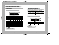
1
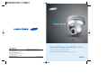
10X Day & Night PTZ Dome Camera SPD-1000 User’s Manual
SALES NETWORK
•
SAMSUNG TECHWIN CO., LTD.
333-1, Sangdaewon 1-dong, Jungwon-gu, Seongnam-si,
Gyeonggi-do 462-807, Korea
TEL : +82-31-730-8931~3 FAX : +82-31-730-8950
•
SAMSUNG OPTO-ELECTRONICS UK, LTD.
Samsung House, 1000 Hillswood Drive, Hillswood Business
Park Chertsey, Surrey KT16 OPS
TEL : +44-1932-45-5308 FAX : +44-1932-45-5325
www.samsungtechwin.com
www.samsungcctv.com
•
TIANJIN SAMSUNG OPTO-ELECTRONICS CO., LTD.
7 Pingchang Rd, Nankai Dist. Tianjin 300190, P.R China
TEL : +86-22-2761-4724(33821) FAX : +86-22-2761-6514
Thank you for purchasing a SAMSUNG CCD CAMERA.
Before attempting to connect or operate this product,
please read these instructions carefully and save this manual for future use.
P/No. : Z6806-0836-01A
VAN 07. 07
ENGLISH
The lightning flash with an arrowhead symbol, within an equilateral triangle is
intended to alert the user to the presence of uninsulated “dangerous voltage”
within the product's enclosure that may be of sufficient magnitude to
constitute a risk of electric shock to persons.
The exclamation point within an equilateral triangle is intended to alert the user
to the presence of important operating and maintenance (servicing)
instructions in the literature accompanying the appliance.
INFORMATION -This equipment has been tested and found to comply with limits
for a Class A digital device, pursuant to part 15 of the FCC Rules. These limits are
designed to provide reasonable protection against harmful interference when the
equipment is operated in a commercial environment. This equipment generates,
uses, and can radiate radio frequency energy and, if not installed and used in
accordance with the instruction manual, may cause harmful interference to radio
communications.
Operation of this equipment in a residential area is likely to cause harmful
interference in which case the user will be required to correct the interference at
his own expense.
WARNING - Changes or modifications not expressly approved by the manufacturer
could void the user’s authority to operate the equipment.
CAUTION : To prevent electric shock and risk of fire hazards:
Do NOT use power sources other than that specified.
Do NOT expose this appliance to rain or moisture.
This installation should be made by a qualified service person and
should conform to all local codes.
Features
10X Zoom Lens with Auto-Focus
Function
The 10X zoom lens having Auto-focus function
magnifies the image up to 100 times when
used with the digital 10X zoom function.
Various Auto Surveillances
*Individual Preset Saving Modes
12 camera adjustment functions can be saved
independently in each Preset menu to provide
optimum images.
*Various Protocols
7 different makersí protocols are supported:
Samsung Techwin, Pelco, Samsung Electronics,
Panasonic, Vicon and Honeywell etc.
*PTZ Trace
4 patterns operated with the joystick can be
saved and replayed by users.
*AUTO Swing
Pan or Tilt is operated in sequence between 2
designated positions.
*Group Search
Maximum 128 Preset positions are toured in
order.
*Tour Search
Maximum 6 Group Search functions are toured
in order.
Day & Night
Day & Night function of ICR (IR Cut-Filter
Removal) and Sens-Up function can achieve
optimum images during day and night.
*Sens-Up function improves the CCD sensitivity by
lengthening the exposure time using electricity.
*Day&Night function enables users to select and
adjust the colour and black and white images
according to the light level.
OSD (On Screen Display)
Items such as Camera ID, Camera Name, Preset
Number, Preset Name, Area Name and Camera
Status are displayed on the monitor. Camera
functions can be set up on the OSD menu screen.
Warnings & Cautions
This information is provided to ensure your safety and to prevent any losses, financial or
otherwise. Please read it carefully and use the product accordingly.
Warning/Attention/Special Mark Messages
Ignoring this information may result in material loss and/or serious
personal injuries including death.
Indicates “Never Allowed.”
128 Preset Positions
A maximum of 128 Preset positions can be
set up. This function enables users to set up
the monitoring place any time.
Digital Flip
When you want to monitor the moving object
below the camera, you can execute the
Digital Flip using the controllerís joystick. The
moving object can be monitored without
screen reverse.
Proportional P/T
Area Masking
Even when the Zoom-In function is On for the
Pan and Tilt speed correction function linked to
the zoom position, fine manual operation is
possible.
Samsung Techwin cares for the environment at all product manufacturing
stages to preserve the environment, and is taking a number of steps to
provide customers with more environment-friendly products.The Eco mark
represents Samsung Techwin s will to create environment-friendly products,
and indicates that the product satisfies the EU RoHS Directive.
For privacy protection, a maximum of 4 areas
can be masked among the surveillance areas
preventing them to be displayed on the screen.
Indicates “No Disassembling.”
Indicates Must Observe.
Contents
Precautions
Part Names and Functions
Body
Main Body Port Block
Cable Connection
Camera Initial Setting
8
10
10
10
11
12
Functional Description
31
OSD Menu Organization
PTZ Camera User Menu Settings
1. Camera Settings
2. Sequence Setting
3. P/T Setting
4. OSD Setting
5. Alarm Setting
6. Initialization Setting
7. Status
31
34
34
42
47
50
54
56
57
Components and Accessories
22
Product Structure and Installation
58
Installation
23
Specifications
61
Precautions
If any unusual odors or smoke comes
from the camera, stop using the product.
Experienced and skilled technicians have to install
this product. Unqualified and personal installation
may cause fire or electric shock. Contact the dealer
for installation.
Do not install the product under humid conditions
or near flammable or explosive gases.
It may cause fire.
Install the product in a place strong
enough to hold it.
It may cause failure, electric shock or fire.
The product may fall.
Do not handle the power plug
with wet hands.
Do not disassemble or insert
foreign objects.
It may cause electric shock.
It may cause failure or electric shock.
8
ENGLISH
Installation by unqualified
persons is not recommended.
Do not install the product in too
hot or too cold environments.
Do not install the camera in
intermittent lighting environments.
Do not use the camera under extreme temperatures (below 10° or above +50°). It may cause poor image quality or
failure. Be especially careful to provide ventilation when
operating the camera under high temperatures.
Do not install the camera under severely
changing lighting environments such as
fluorescent lamps. It may cause the camera
to work improperly.
Never drop the camera or subject
it to severe shocks or vibrations.
Do not aim the camera at the sun
or any other strong light source.
It may cause failure.
It may cause fatal damage to CCD device or
internal circuit.
Do not touch the front glass of
the camera.
It is the most important part of camera. Be
careful not to mark it with fingerprints.
Do not install the camera where it might
be exposed to rain, water or spillages.
If the camera gets wet, it may cause failure.
9
Part Names and Functions
Body
Cable Connection
Main Body Port Block
Power Input Jack
Camera ID Setting Switch
Communication Protocols, Transmission Mode,Termination Setting
Switch
Controller and Alarm Input/Output Connection Terminal
Auxiliary Video Terminal
10
11
Part Names and Functions
Camera Initial Settings
Setting Baud Rate Based on DVR Model
If the speed dome camera is controlled not by the camera controller but by a
DVR, set the communication speed based on the DVR model as follows.
Setting Communications Protocol
Use the SW2 #1~#5 of installation bracket to set the communications protocol.
Baud Rate(BPS)
NO.
Protocol
1
Samsung
9,600
2
Samsung
19,200
3
Pelco-D
2,400
4
Pelco-D
4,800
5
Samsung Elec.
9,600
6
Samsung Elec.
19,200
7
Panasonic
9,600
8
Panasonic
19,200
9
Vicon
4,800
10
Vicon
9,600
11
AD
4,800
12
Bosch
9,600
13
Bosch
19,200
14
Honeywell
9,600
15
Honeywell
19,200
16
Sungjin
4,800
17 32
Reserve
SW2-#1
OFF
OFF
OFF
OFF
OFF
OFF
OFF
OFF
OFF
OFF
OFF
OFF
OFF
OFF
OFF
OFF
SW2-#2
OFF
OFF
OFF
OFF
OFF
OFF
OFF
OFF
ON
ON
ON
ON
ON
ON
ON
ON
SW2-#3
OFF
OFF
OFF
OFF
ON
ON
ON
ON
OFF
OFF
OFF
OFF
ON
ON
ON
ON
SW2-#4
OFF
OFF
ON
ON
OFF
OFF
ON
ON
OFF
OFF
ON
ON
OFF
OFF
ON
ON
SW2-#5
OFF
ON
OFF
ON
OFF
ON
OFF
ON
OFF
ON
OFF
ON
OFF
ON
OFF
ON
Protocol
DVR Model
Samsung
Pelco
Samsung Elec.
SVR-950
SVR-1640
SVR-1650
9600,19200
9600,19200
9600,19200
2400,4800
2400,4800
2400,4800
19,200
19,200
19,200
Setting Transmission Mode
Set the transmission mode using the ON/OFF of the Dip Switch 2.
SW2- #6
Function
Transmission Mode
Selection
ON
Full
(DVR)
Notes
• Factory Setting: OFF
Notes
• Default Setting : Samsung 9,600 bps
• AD, Bosch is now preparing.
12
13
OFF
Half
(SCC-3100A)
Part Names and Functions
Setting RS-485 Termination
Set the termination using the ON/OFF of #7~#8 of the Dip Switch 2.
Location of Camera Connection
Termination of Longest Path
On the Path
SW2 - #7
ON
OFF
SW2 - #8
ON
OFF
Notes
• Factory Setting: OFF
Setting Camera ID Switch
Set the Camera ID using the ON/OFF of #1~#8 of the Dip Switch 1.
1
2
3
4
ON
5
6
7
8
ON
OFF
SW1
Notes
• Factory Setting: ID=001
ID=0, 160. 175 is cannot be used.
14
Camera ID
0
1
2
3
4
5
6
7
8
9
10
11
12
13
14
15
16
17
18
19
20
21
22
23
24
25
26
27
28
29
30
31
32
33
34
35
36
37
38
39
40
41
42
43
44
45
46
47
48
49
SW1-#1
OFF
OFF
OFF
OFF
OFF
OFF
OFF
OFF
OFF
OFF
OFF
OFF
OFF
OFF
OFF
OFF
OFF
OFF
OFF
OFF
OFF
OFF
OFF
OFF
OFF
OFF
OFF
OFF
OFF
OFF
OFF
OFF
OFF
OFF
OFF
OFF
OFF
OFF
OFF
OFF
OFF
OFF
OFF
OFF
OFF
OFF
OFF
OFF
OFF
OFF
SW1-#2
OFF
OFF
OFF
OFF
OFF
OFF
OFF
OFF
OFF
OFF
OFF
OFF
OFF
OFF
OFF
OFF
OFF
OFF
OFF
OFF
OFF
OFF
OFF
OFF
OFF
OFF
OFF
OFF
OFF
OFF
OFF
OFF
OFF
OFF
OFF
OFF
OFF
OFF
OFF
OFF
OFF
OFF
OFF
OFF
OFF
OFF
OFF
OFF
OFF
OFF
SW1-#3
OFF
OFF
OFF
OFF
OFF
OFF
OFF
OFF
OFF
OFF
OFF
OFF
OFF
OFF
OFF
OFF
OFF
OFF
OFF
OFF
OFF
OFF
OFF
OFF
OFF
OFF
OFF
OFF
OFF
OFF
OFF
OFF
ON
ON
ON
ON
ON
ON
ON
ON
ON
ON
ON
ON
ON
ON
ON
ON
ON
ON
SW1-#4
OFF
OFF
OFF
OFF
OFF
OFF
OFF
OFF
OFF
OFF
OFF
OFF
OFF
OFF
OFF
OFF
ON
ON
ON
ON
ON
ON
ON
ON
ON
ON
ON
ON
ON
ON
ON
ON
OFF
OFF
OFF
OFF
OFF
OFF
OFF
OFF
OFF
OFF
OFF
OFF
OFF
OFF
OFF
OFF
ON
ON
15
SW1-#5
OFF
OFF
OFF
OFF
OFF
OFF
OFF
OFF
ON
ON
ON
ON
ON
ON
ON
ON
OFF
OFF
OFF
OFF
OFF
OFF
OFF
OFF
ON
ON
ON
ON
ON
ON
ON
ON
OFF
OFF
OFF
OFF
OFF
OFF
OFF
OFF
ON
ON
ON
ON
ON
ON
ON
ON
OFF
OFF
SW1-#6
OFF
OFF
OFF
OFF
ON
ON
ON
ON
OFF
OFF
OFF
OFF
ON
ON
ON
ON
OFF
OFF
OFF
OFF
ON
ON
ON
ON
OFF
OFF
OFF
OFF
ON
ON
ON
ON
OFF
OFF
OFF
OFF
ON
ON
ON
ON
OFF
OFF
OFF
OFF
ON
ON
ON
ON
OFF
OFF
SW1-#7
OFF
OFF
ON
ON
OFF
OFF
ON
ON
OFF
OFF
ON
ON
OFF
OFF
ON
ON
OFF
OFF
ON
ON
OFF
OFF
ON
ON
OFF
OFF
ON
ON
OFF
OFF
ON
ON
OFF
OFF
ON
ON
OFF
OFF
ON
ON
OFF
OFF
ON
ON
OFF
OFF
ON
ON
OFF
OFF
SW1-#8
OFF
ON
OFF
ON
OFF
ON
OFF
ON
OFF
ON
OFF
ON
OFF
ON
OFF
ON
OFF
ON
OFF
ON
OFF
ON
OFF
ON
OFF
ON
OFF
ON
OFF
ON
OFF
ON
OFF
ON
OFF
ON
OFF
ON
OFF
ON
OFF
ON
OFF
ON
OFF
ON
OFF
ON
OFF
ON
Part Names and Functions
Camera ID
50
51
52
53
54
55
56
57
58
59
60
61
62
63
64
65
66
67
68
69
70
71
72
73
74
75
76
77
78
79
80
81
82
83
84
85
86
87
88
89
90
91
92
93
94
95
96
97
98
99
SW1-#1
OFF
OFF
OFF
OFF
OFF
OFF
OFF
OFF
OFF
OFF
OFF
OFF
OFF
OFF
OFF
OFF
OFF
OFF
OFF
OFF
OFF
OFF
OFF
OFF
OFF
OFF
OFF
OFF
OFF
OFF
OFF
OFF
OFF
OFF
OFF
OFF
OFF
OFF
OFF
OFF
OFF
OFF
OFF
OFF
OFF
OFF
OFF
OFF
OFF
OFF
SW1-#2
OFF
OFF
OFF
OFF
OFF
OFF
OFF
OFF
OFF
OFF
OFF
OFF
OFF
OFF
ON
ON
ON
ON
ON
ON
ON
ON
ON
ON
ON
ON
ON
ON
ON
ON
ON
ON
ON
ON
ON
ON
ON
ON
ON
ON
ON
ON
ON
ON
ON
ON
ON
ON
ON
ON
SW1-#3
ON
ON
ON
ON
ON
ON
ON
ON
ON
ON
ON
ON
ON
ON
OFF
OFF
OFF
OFF
OFF
OFF
OFF
OFF
OFF
OFF
OFF
OFF
OFF
OFF
OFF
OFF
OFF
OFF
OFF
OFF
OFF
OFF
OFF
OFF
OFF
OFF
OFF
OFF
OFF
OFF
OFF
OFF
ON
ON
ON
ON
SW1-#4
ON
ON
ON
ON
ON
ON
ON
ON
ON
ON
ON
ON
ON
ON
OFF
OFF
OFF
OFF
OFF
OFF
OFF
OFF
OFF
OFF
OFF
OFF
OFF
OFF
OFF
OFF
ON
ON
ON
ON
ON
ON
ON
ON
ON
ON
ON
ON
ON
ON
ON
ON
OFF
OFF
OFF
OFF
16
SW1-#5
OFF
OFF
OFF
OFF
OFF
OFF
ON
ON
ON
ON
ON
ON
ON
ON
OFF
OFF
OFF
OFF
OFF
OFF
OFF
OFF
ON
ON
ON
ON
ON
ON
ON
ON
OFF
OFF
OFF
OFF
OFF
OFF
OFF
OFF
ON
ON
ON
ON
ON
ON
ON
ON
OFF
OFF
OFF
OFF
SW1-#6
OFF
OFF
ON
ON
ON
ON
OFF
OFF
OFF
OFF
ON
ON
ON
ON
OFF
OFF
OFF
OFF
ON
ON
ON
ON
OFF
OFF
OFF
OFF
ON
ON
ON
ON
OFF
OFF
OFF
OFF
ON
ON
ON
ON
OFF
OFF
OFF
OFF
ON
ON
ON
ON
OFF
OFF
OFF
OFF
SW1-#7
ON
ON
OFF
OFF
ON
ON
OFF
OFF
ON
ON
OFF
OFF
ON
ON
OFF
OFF
ON
ON
OFF
OFF
ON
ON
OFF
OFF
ON
ON
OFF
OFF
ON
ON
OFF
OFF
ON
ON
OFF
OFF
ON
ON
OFF
OFF
ON
ON
OFF
OFF
ON
ON
OFF
OFF
ON
ON
SW1-#8
OFF
ON
OFF
ON
OFF
ON
OFF
ON
OFF
ON
OFF
ON
OFF
ON
OFF
ON
OFF
ON
OFF
ON
OFF
ON
OFF
ON
OFF
ON
OFF
ON
OFF
ON
OFF
ON
OFF
ON
OFF
ON
OFF
ON
OFF
ON
OFF
ON
OFF
ON
OFF
ON
OFF
ON
OFF
ON
Camera ID
100
101
102
103
104
105
106
107
108
109
110
111
112
113
114
115
116
117
118
119
120
121
122
123
124
125
126
127
128
129
130
131
132
133
134
135
136
137
138
139
140
141
142
143
144
145
146
147
148
149
SW1-#1
OFF
OFF
OFF
OFF
OFF
OFF
OFF
OFF
OFF
OFF
OFF
OFF
OFF
OFF
OFF
OFF
OFF
OFF
OFF
OFF
OFF
OFF
OFF
OFF
OFF
OFF
OFF
OFF
ON
ON
ON
ON
ON
ON
ON
ON
ON
ON
ON
ON
ON
ON
ON
ON
ON
ON
ON
ON
ON
ON
SW1-#2
ON
ON
ON
ON
ON
ON
ON
ON
ON
ON
ON
ON
ON
ON
ON
ON
ON
ON
ON
ON
ON
ON
ON
ON
ON
ON
ON
ON
OFF
OFF
OFF
OFF
OFF
OFF
OFF
OFF
OFF
OFF
OFF
OFF
OFF
OFF
OFF
OFF
OFF
OFF
OFF
OFF
OFF
OFF
SW1-#3
ON
ON
ON
ON
ON
ON
ON
ON
ON
ON
ON
ON
ON
ON
ON
ON
ON
ON
ON
ON
ON
ON
ON
ON
ON
ON
ON
ON
OFF
OFF
OFF
OFF
OFF
OFF
OFF
OFF
OFF
OFF
OFF
OFF
OFF
OFF
OFF
OFF
OFF
OFF
OFF
OFF
OFF
OFF
SW1-#4
OFF
OFF
OFF
OFF
OFF
OFF
OFF
OFF
OFF
OFF
OFF
OFF
ON
ON
ON
ON
ON
ON
ON
ON
ON
ON
ON
ON
ON
ON
ON
ON
OFF
OFF
OFF
OFF
OFF
OFF
OFF
OFF
OFF
OFF
OFF
OFF
OFF
OFF
OFF
OFF
ON
ON
ON
ON
ON
ON
17
SW1-#5
OFF
OFF
OFF
OFF
ON
ON
ON
ON
ON
ON
ON
ON
OFF
OFF
OFF
OFF
OFF
OFF
OFF
OFF
ON
ON
ON
ON
ON
ON
ON
ON
OFF
OFF
OFF
OFF
OFF
OFF
OFF
OFF
ON
ON
ON
ON
ON
ON
ON
ON
OFF
OFF
OFF
OFF
OFF
OFF
SW1-#6
ON
ON
ON
ON
OFF
OFF
OFF
OFF
ON
ON
ON
ON
OFF
OFF
OFF
OFF
ON
ON
ON
ON
OFF
OFF
OFF
OFF
ON
ON
ON
ON
OFF
OFF
OFF
OFF
ON
ON
ON
ON
OFF
OFF
OFF
OFF
ON
ON
ON
ON
OFF
OFF
OFF
OFF
ON
ON
SW1-#7
OFF
OFF
ON
ON
OFF
OFF
ON
ON
OFF
OFF
ON
ON
OFF
OFF
ON
ON
OFF
OFF
ON
ON
OFF
OFF
ON
ON
OFF
OFF
ON
ON
OFF
OFF
ON
ON
OFF
OFF
ON
ON
OFF
OFF
ON
ON
OFF
OFF
ON
ON
OFF
OFF
ON
ON
OFF
OFF
SW1-#8
OFF
ON
OFF
ON
OFF
ON
OFF
ON
OFF
ON
OFF
ON
OFF
ON
OFF
ON
OFF
ON
OFF
ON
OFF
ON
OFF
ON
OFF
ON
OFF
ON
OFF
ON
OFF
ON
OFF
ON
OFF
ON
OFF
ON
OFF
ON
OFF
ON
OFF
ON
OFF
ON
OFF
ON
OFF
ON
Part Names and Functions
Camera ID
150
151
152
153
154
155
156
157
158
159
160
161
162
163
164
165
166
167
168
169
170
171
172
173
174
175
176
177
178
179
180
181
182
183
184
185
186
187
188
189
190
191
192
193
194
195
196
197
198
199
SW1-#1
ON
ON
ON
ON
ON
ON
ON
ON
ON
ON
ON
ON
ON
ON
ON
ON
ON
ON
ON
ON
ON
ON
ON
ON
ON
ON
ON
ON
ON
ON
ON
ON
ON
ON
ON
ON
ON
ON
ON
ON
ON
ON
ON
ON
ON
ON
ON
ON
ON
ON
SW1-#2
OFF
OFF
OFF
OFF
OFF
OFF
OFF
OFF
OFF
OFF
OFF
OFF
OFF
OFF
OFF
OFF
OFF
OFF
OFF
OFF
OFF
OFF
OFF
OFF
OFF
OFF
OFF
OFF
OFF
OFF
OFF
OFF
OFF
OFF
OFF
OFF
OFF
OFF
OFF
OFF
OFF
OFF
ON
ON
ON
ON
ON
ON
ON
ON
SW1-#3
OFF
OFF
OFF
OFF
OFF
OFF
OFF
OFF
OFF
OFF
ON
ON
ON
ON
ON
ON
ON
ON
ON
ON
ON
ON
ON
ON
ON
ON
ON
ON
ON
ON
ON
ON
ON
ON
ON
ON
ON
ON
ON
ON
ON
ON
OFF
OFF
OFF
OFF
OFF
OFF
OFF
OFF
SW1-#4
ON
ON
ON
ON
ON
ON
ON
ON
ON
ON
OFF
OFF
OFF
OFF
OFF
OFF
OFF
OFF
OFF
OFF
OFF
OFF
OFF
OFF
OFF
OFF
ON
ON
ON
ON
ON
ON
ON
ON
ON
ON
ON
ON
ON
ON
ON
ON
OFF
OFF
OFF
OFF
OFF
OFF
OFF
OFF
18
SW1-#5
OFF
OFF
ON
ON
ON
ON
ON
ON
ON
ON
OFF
OFF
OFF
OFF
OFF
OFF
OFF
OFF
ON
ON
ON
ON
ON
ON
ON
ON
OFF
OFF
OFF
OFF
OFF
OFF
OFF
OFF
ON
ON
ON
ON
ON
ON
ON
ON
OFF
OFF
OFF
OFF
OFF
OFF
OFF
OFF
SW1-#6
ON
ON
OFF
OFF
OFF
OFF
ON
ON
ON
ON
OFF
OFF
OFF
OFF
ON
ON
ON
ON
OFF
OFF
OFF
OFF
ON
ON
ON
ON
OFF
OFF
OFF
OFF
ON
ON
ON
ON
OFF
OFF
OFF
OFF
ON
ON
ON
ON
OFF
OFF
OFF
OFF
ON
ON
ON
ON
SW1-#7
ON
ON
OFF
OFF
ON
ON
OFF
OFF
ON
ON
OFF
OFF
ON
ON
OFF
OFF
ON
ON
OFF
OFF
ON
ON
OFF
OFF
ON
ON
OFF
OFF
ON
ON
OFF
OFF
ON
ON
OFF
OFF
ON
ON
OFF
OFF
ON
ON
OFF
OFF
ON
ON
OFF
OFF
ON
ON
SW1-#8
OFF
ON
OFF
ON
OFF
ON
OFF
ON
OFF
ON
OFF
ON
OFF
ON
OFF
ON
OFF
ON
OFF
ON
OFF
ON
OFF
ON
OFF
ON
OFF
ON
OFF
ON
OFF
ON
OFF
ON
OFF
ON
OFF
ON
OFF
ON
OFF
ON
OFF
ON
OFF
ON
OFF
ON
OFF
ON
Camera ID
200
201
202
203
204
205
206
207
208
209
210
211
212
213
214
215
216
217
218
219
220
221
222
223
224
225
226
227
228
229
230
231
232
233
234
235
236
237
238
239
240
241
242
243
244
245
246
247
248
249
SW1-#1
ON
ON
ON
ON
ON
ON
ON
ON
ON
ON
ON
ON
ON
ON
ON
ON
ON
ON
ON
ON
ON
ON
ON
ON
ON
ON
ON
ON
ON
ON
ON
ON
ON
ON
ON
ON
ON
ON
ON
ON
ON
ON
ON
ON
ON
ON
ON
ON
ON
ON
SW1-#2
ON
ON
ON
ON
ON
ON
ON
ON
ON
ON
ON
ON
ON
ON
ON
ON
ON
ON
ON
ON
ON
ON
ON
ON
ON
ON
ON
ON
ON
ON
ON
ON
ON
ON
ON
ON
ON
ON
ON
ON
ON
ON
ON
ON
ON
ON
ON
ON
ON
ON
SW1-#3
OFF
OFF
OFF
OFF
OFF
OFF
OFF
OFF
OFF
OFF
OFF
OFF
OFF
OFF
OFF
OFF
OFF
OFF
OFF
OFF
OFF
OFF
OFF
OFF
ON
ON
ON
ON
ON
ON
ON
ON
ON
ON
ON
ON
ON
ON
ON
ON
ON
ON
ON
ON
ON
ON
ON
ON
ON
ON
SW1-#4
OFF
OFF
OFF
OFF
OFF
OFF
OFF
OFF
ON
ON
ON
ON
ON
ON
ON
ON
ON
ON
ON
ON
ON
ON
ON
ON
OFF
OFF
OFF
OFF
OFF
OFF
OFF
OFF
OFF
OFF
OFF
OFF
OFF
OFF
OFF
OFF
ON
ON
ON
ON
ON
ON
ON
ON
ON
ON
19
SW1-#5
ON
ON
ON
ON
ON
ON
ON
ON
OFF
OFF
OFF
OFF
OFF
OFF
OFF
OFF
ON
ON
ON
ON
ON
ON
ON
ON
OFF
OFF
OFF
OFF
OFF
OFF
OFF
OFF
ON
ON
ON
ON
ON
ON
ON
ON
OFF
OFF
OFF
OFF
OFF
OFF
OFF
OFF
ON
ON
SW1-#6
OFF
OFF
ON
ON
ON
ON
OFF
OFF
OFF
OFF
ON
ON
ON
ON
OFF
OFF
OFF
OFF
ON
ON
ON
ON
OFF
OFF
OFF
OFF
ON
ON
ON
ON
OFF
OFF
OFF
OFF
ON
ON
ON
ON
OFF
OFF
OFF
OFF
ON
ON
ON
ON
OFF
OFF
OFF
OFF
SW1-#7
OFF
OFF
ON
ON
OFF
OFF
ON
ON
OFF
OFF
ON
ON
OFF
OFF
ON
ON
OFF
OFF
ON
ON
OFF
OFF
ON
ON
OFF
OFF
ON
ON
OFF
OFF
ON
ON
OFF
OFF
ON
ON
OFF
OFF
ON
ON
OFF
OFF
ON
ON
OFF
OFF
ON
ON
OFF
OFF
SW1-#8
OFF
ON
OFF
ON
OFF
ON
OFF
ON
OFF
ON
OFF
ON
OFF
ON
OFF
ON
OFF
ON
OFF
ON
OFF
ON
OFF
ON
OFF
ON
OFF
ON
OFF
ON
OFF
ON
OFF
ON
OFF
ON
OFF
ON
OFF
ON
OFF
ON
OFF
ON
OFF
ON
OFF
ON
OFF
ON
Part Names and Functions
Camera ID
250
251
252
253
254
255
SW1-#1
ON
ON
ON
ON
ON
ON
SW1-#2
ON
ON
ON
ON
ON
ON
SW1-#3
ON
ON
ON
ON
ON
ON
SW1-#4
ON
ON
ON
ON
ON
ON
SW1-#5
ON
ON
ON
ON
ON
ON
SW1-#6
OFF
OFF
ON
ON
ON
ON
SW1-#7
ON
ON
OFF
OFF
ON
ON
SW1-#8
OFF
ON
OFF
ON
OFF
ON
Auxiliary Video Out Port
When the product is installed in a place where video signal connection through the BNC
port is unavailable, you can connect a video cable using the Auxiliary Video Out Port. In
this case, connect using the BNC auxiliary cable that is supplied as an accessory.
Connect the controller and alarm input and output signal (main body port block)
Setting Termination Resistance
Pin Order
1
2
3
4
5
6
7
8
9
10
Pin Name
D+
DG
S1
S2
G
+V
NO
NC
CM
Purpose
RS-485 Data+
RS-485 DataGND
Alarm Signal Input Port #1
Alarm Signal Input Port #2
GND
+12V Output Port
Alarm Signal Output Port #1 (For Normal Open)
Alarm Signal Output Por #1 (For Normal Close)
Alarm Signal Output (For Common)
20
In order to prevent signal reduction, the termination resistance of the 2 end units,
which are the distant paths for camera and controller to be connected on the RS485
interface, should be connected. As the termination resistance is built in the camera,
whether to make the termination resistance valid or invalid is selected with the DIP
switch. See the connection diagram below for determining to which device the
termination resistance will be connected to. Set up the termination resistance in the
dark products. The installation distance of the product for the termination resistance
setting should be less than 1.2 Km. (Maximum cable length is 1.2 Km according to the
RS-485 standards.)
21
Installation
Components and Accessories
ENGLISH
Accessories
power adapter (DC 12VV, Peak 4A)
BNC auxiliary cable
User s Manual
installation cover
installation template
Preparation for Cable
To install and use the SPD-1000, the following cables should be used.
• Power Adapter Cable
The cable connected to the power input terminal of SPD-1000 is shown below
with a rated voltage of DC 12V 4A.
2 installation brackets
3 installation bracket
fixing screws
1 loose-proof
screw
• Video Cable
The cable connected to the video output terminal and to the monitor of SPD1000 is the BNC cable shown below.
Products Sold Separately
The following products are provided separately.
• CONTROLLER
Camera Controller : SCC-3100A
• Communications Cable
• Accessori Housing
Wall Type Mount : STB-280PW
Wall Type Mount : STB-230PW
Dome Housing : STH-1000PI
The cable connected to the controller of SPD-1000 for RS-485 communication is shown
below.
Notes
• See pages 25 for product images.
Notes
• Video cable and RS-485 communication cable are not provided in this product’s
package.
22
23
Installation
Cable Connection
Installation of SPD-1000
1. First, connect one end of the BNC
video cable connector to the Video
Output Terminal.
Monitor
In Terminal
2. Next, connect the other end of the
connector to the Video Input Terminal
of the monitor.
Video Out
Terminal
Monitor
DATA BOX
Controller Connection
Terminal
3. Connect the Controller Connection Terminal
of SPD-1000 and the external
Controller.
• Precautions for Installation
- Check that the installation location can safely bear four times the weight of
the camera and its installation fittings.
- When fixing the ceiling installation bracket, use the supplied installation
template and fixing screws.
- Take care not to drop the product during installation. Do not allow anyone to
stand below the installation area.
• Optional Products for Installation
1) Wall Mount (STB-280PW)
This housing is used to install the camera on an indoor wall or ceiling using an
external conduit.
Controller
4. Then, connect the Power Adapter Cable. Use a driver (-) to screw one part of
the Power Adapter consisting of two lines to the Power Input Terminal of
the camera holder.
2) Wall Mount(STB-230PW)
This housing is used to install the camera on an indoor wall
5. Connect the Power
Adapter’s plug to the Power
Outlet.
Power Adapter
for
24
4) Dome Housing (STH-1000PI)
This housing is used to install the camera in a location
that is dusty, or a place where extra protection for the
camera is required.
25
Installation
Installing the SPD-1000 on a Ceiling
1. Prepare the accessories in the camera box (power adapter, installation template, BNC
auxiliary cable, 1 loose-proof screw, 3 installation bracket fixing screws, 2 installation
brackets, installation cover) and a tool for making a hole in the ceiling.
3. Align the arrow on the ceiling attachment installation bracket with the front of
the template, fix the bracket by fastening the 3 screws through the holes, and
connect the external incoming cables (video cable, controller cable and power
cord) to the camera.
on the ceiling
power adapter(DC 12V, Peak 4A)
3 installation bracket
fixing screws
installation template
BNC auxiliary cable
2 installation brackets
1 loose-proof
screw
installation cover
on the ceiling
2. Attach the installation template to the ceiling where
you want to install the camera, make a hole of at
least 65mm in diameter, and 3 holes for fixing
screws according to the marks on the template,
and pull the external incoming cables out of the
hole.
on the ceiling
template
4. Assemble the camera, which should
already have been attached to the product
installation bracket, to the ceiling
attachment installation bracket, facing
forwards, and fix the camera with the
supplied fixing screw.
the external
incoming cables
on the ceiling
Notes
*Precautions before Attaching the Installation Template
• Installation Location: Check that the function and performance of the camera installed on the ceiling will not
be adversely affected by the external environment, and that the ceiling can adequately support the weight of
the camera.
• Installation Direction: Determine the main direction of the camera in advance and attach the template so that
the front of the template is in line with the camera direction.
• Caution: Since there is a danger of the product falling during installation, take care not to allow anyone to
stand below the installation area.
26
5. To complete installation, rotate the
installation cover along the groove
of the ceiling attachment bracket,
and fix it.
install cover
27
Installation
Installing the SPD-1000 Wall Mount
1. Prepare the accessories in the camera box (power adapter, BNC auxiliary cable, 1
loose-proof screw, 2 installation brackets, installation cover) and the wall mount
(STB-280PW or STB-230PW) and 3 installation bracket fixing screws in the mount
packaging box.
power adapter(DC 12V, Peak 4A)
1 looseproof screw
BNC auxiliary cable
installation cover
STB-280PW
2. Fix the wall mount (STB-280PW) with 3 screws to
the wall where the camera is to be installed, as
shown in the figure on the right.
3. Fix the wall bracket and the wall surface attachment installation bracket onto
the wall mount (STB-280PW) with the screws supplied, as shown in the
figure on the right, and connect the external incoming cables (video cable,
controller cable and power cord) to the camera.
Wall
2 installation brackets
STB-230PW
Wall
4. Assemble the camera, which should already have been attached to the product
installation bracket, to the wall attachment installation bracket, facing forwards, and
fix the camera with the supplied fixing screw.
Notes
*Precautions before Attaching the Installation Template
Wall
• Installation Place: Check that the function and performance of the camera installed on the wall will not be
adversely affected by the external environment, and that the ceiling can adequately support the weight of the
camera.
• Installation Direction: Determine the main direction of the camera in advance and attach the template so that
the front of the template is in line with the camera direction.
• Caution: Since there is a danger of the product falling during installation, take care not to allow anyone to
stand below the installation area.
28
29
Functional Description
Installation
5. To complete installation, rotate the installation cover along the groove of
the ceiling attachment bracket, and fix it.
Wall
OSD Menu Organization
PTZ camera can be set up on the OSD (On Screen Display) menu displayed on the video
monitor by the camera controller. The joystick operations in the OSD menu are as follows. In
addition, sending control codes to the camera from the PC can also use the camera functions.
Menu
TILT UP
TILT DOWN
P1
Function
Move up on the OSD menu
Move down on the OSD menu
P2
Focus
P3
Focus Mode
Zoom Tracking
Digital Zoom
Installing the Dome Housing (STH-1000PI)
White
Balance
To install the Dome Housing (STH-1000PI), fix it instead of installing the cover
in the last step “Installing the SPD-1000 on a Ceiling” on page 26 and “Installing
the SPD-1000 Wall Mount” on page 28.
• When the Dome Housing is
installed on the ceiling
• When the Dome Housing is
installed on the wall
Wall
AWB Mode
Brightness
Iris
Camera
Setting
Exposure
Shutter
on the ceiling
Sens-Up
AGC
SSNR
Others
High.Middle/Low/Off
High/Normal/Off
High/Middle/Low/Off
Auto
B/W
Color
Sync
Image Adj.
Freeze
30
Menu
PAN LEFT
PAN RIGHT
Function
Move left on the OSD menu
Move right on the OSD menu
P4
Auto/Manual/One Shot AF
Mode On/Off
Speed Slow/Fast
Off(2~10X)
ATW/AWC/MANUAL
ATW
-ATW(I): Indoor -ATW(O): Outdoor
Manual
-Red -Blue
25
Auto
Manual Iris Level
--A.FLK
Manual 1/60~1/120,000,x2~x128
Auto Sens-Up Limit x2~x128
Off
Defaults
One Shot AF
ON
Fast
OFF
ATW(O)
29
41
025
Auto
100
ESC
1/60
x4
OFF
Normal
Low
Burst Level
Sharpness
Color
On/Off
31
060
Internal
008
050
OFF
Functional Description
P1
P2
Preset
Swign SEQ
Group SEQ
Tour SEQ
Sequence
Setting
PTZ Trace
P3
Setting Edit Execute
Pan Swing
Tilt Swing
P/T Swing
Group1
Group2
Group3
Group4
Group5
Group6
Setting Execute Clear
Trace1
Trace2
Trace3
Trace4
Mode
Auto Run
Replay
Replay
Replay
Replay
Off
Preset
Swing
Group
Tour
Trace
A.Pan
Clear
Clear
Clear
Clear
Clear
Clear
Clear
Clear
Clear
P/T
Setting
OSD
Setting
Language
OFF
Preset No
Swing Mode Pan/Tilt/P&T
Group No
20-50
10-45
Input 1
32
25
30 sec
Area Setting
Area3
ON
ON
MANUAL
ON
ON
ON
OFF
OFF
English
NC/NO/OFF
L/H(Priority)
Preset/Swing/Group/Tour
/Trace/A.PAN/OFF
1~2, MD
1-59(Sec)
1-59(Min)
1-59(Hour)
Enable
ON/OFF
MD Dwell Time
ON/OFF
Power On Reset
Cancel Execute
Initial Position
Position ON/OFF
Factory Default Set
Cancel Execute
Camera Default Set
Cancel Execute
Auto Refresh
OFF, 1~7Days
Output
Initialize
Area Name
Position
ON/OFF
Area2
01(Min)
1-59(Sec) / 1-59(Min)
Status
Notes
Area4
Area Masking
Input 2
Alarm
Setting
OFF
ON/OFF
ON/OFF
Mask3
Mask4
ON / OFF
ON / OFF
Manual (10,20,30,40,50,60)
ON / OFF
ON / OFF Edit
ON / OFF
ON / OFF Edit
ON / OFF
ON / OFF
ON / OFF
English,Chinese,Francais,
Deutsch,Espanol,Italiano
Output Clear
Area1
P/T
Setting
Prop. P/T
Digital Flip
Jog Speed
Camera ID
Camera Name
Preset Number
Preset Name
Sequence Status
Area Name
PTZ Position
Memorize
Memorize
Memorize
Memorize
On/Off
Position
Position
Defaults
Trace1~Trace4
Auto Pan Speed
Tilt Angle
5,10,20,30(Sec), 1,2(Min)
Time
Power On
Resume
Pan Limit
Tilt Limit
P4
Status
Execute
Execute
Execute
Execute
Execute
Execute
Execute
Execute
Execute
Clear
Setting
Setting
Setting
Setting
Setting
Setting
Setting
Setting
Setting
• Preset setting is only possible on the OSD menu or using the controller.
Position
ON/OFF
Mask1
Mask2
32
33
OFF
30sec
OFF
Functional Description
Symbol Description
1. Motion Stabilization Stand-by Operation
- “D” symbol is flashing on the right top of
the screen.
2. Alarm Input #1, 2 Sensor Operation
- “ ”, “ ” symbols are flashing on the
right top of the screen.
3. Alarm Output Operation
- Symbols are flashing on the right top of
the screen.
4. Motion Detect Operation
- “Man Icon” is flashing on the right top of
the screen.
5. When there are sub menus under the
selected OSD menu
- Numbers are displayed in white colour like
on the right top of the screen.
6. When there is no sub menu under the
selected OSD menu
- Numbers are displayed in black colour like
“ ” on the right top of the screen.
PTZ Camera User Menu Settings
• Execution of OSD Menu : After checking if the camera is in manual operation mode,
press the OSD Menu key. The following commands are displayed on the monitor screen.
Main Menu
• Main Menu
The selection key moves up and down. Press the
execution key switch on the selected menu to
change the setup menu. Press the ESC key to exit
the OSD Menu.
Camera Setting
Sequence Setting
P/T Setting
OSD Setting
Alarm Setting
Initialize
Status
Focus Mode
Auto
: The camera adjusts the focus automatically while monitoring the
screen continuously in the auto mode. In the auto focusing mode,
zoom key operation is not recognized as the input of the focus key.
Manual
: In the manual mode, users can adjust the camera focus manually.
One Shot AF : Only when the camera does not move, it turns into the auto mode. It
is the same as the manual mode.
Zoom Tracking
Mode: When you select ON, the Focus function is executed when the Zoom function
is on. When you select OFF, the Focus function is not executed even when
the Zoom function is on.
Speed: Fast will speed up the Zoom. Slow will slow down the Zoom.
Digital Zoom
Magnification of the Digital Zoom can be selected among Off, 2X~10X.
*It is recommended that the Digital Zoom should be set up before the preset operation.
Notes
Digital Zoom
•As the digital zoom magnification increases, the image quality is lowered.
1) Camera Setting
Select the Camera Setting on the Main Menu screen to control camera settings
• Camera Setting Menu
Camera Setting
Focus
White Balance
Exposure
Back Light
AGC
SSNR
Day & Night
Others
FOCUS
In Focus menu, you can set up the focus mode among Auto, Manual or One
Shot AF.
Focus
Focus Mode
ONE SHOT AF
Zoom Tracking
Digital Zoom OFF
ATW(O)
OFF
NORMAL
LOW
COLOR
34
Auto-focus
• Auto-focus may not function normally under the following conditions.
- When the light level in the surveillance area is low
- When the slow-shutter works
- When the amplification is increased
- When the light level in the surveillance area is excessively high
- When the objects in the long and short distance are under the same surveillance area
- When there is no contrast (white and black) in the object (e.g. sky or wall)
- When the thin horizontal line is captured
35
Functional Description
Exposure
White Balance
The White Balance function corrects the abnormal white colour into the
normal white colour under any colour temperature lighting.
Select the mode among ATW, AWC and Manual. ATW is selected by default.
Camera Setting
Focus
White Balance
Exposure
Back Light
AGC
SSNR
Day & Night
Others
ATW(O)
OFF
NORMAL
LOW
COLOR
WB Mode
ATW: Balances the colour automatically depending on the source of light from
1,800~10,500K colour temperature.
* Indoor[ATW(I)] : Use this mode in the area under the limited colour temperature.
* Outdoor[ATW(O)] : Use this mode in the area under the broad colour temperature.
AWC: Set up the lighting to the objects and corrects the right colour temperature to that of a
white object. Camera works under the setup conditions. For the most appropriate
condition under the current illumination, capture the white paper and then change the
mode into AWC. Press the Enter key and then AWC Start will be displayed. When the
adjustment is completed after pressing the Enter key for AWC Start, go to the upper
menu. When conditions change, adjust the white balance function again.
Manual: Fine tuning is possible through this manual control mode. Select the colour temperature
and increase or decrease the Red or Blue values to shift the colour of the object.
* Red : Red Gain can be changed.
* Blue : Blue Gain can be changed.
Camera exposure can be controlled.
Camera Setting
Focus
White Balance
Exposure
Back Light
AGC
SSNR
Day & Night
Others
Exposure
Brightness
Iris
Shtter
Sens-Up
ATW(O)
OFF
NORMAL
LOW
COLOR
025
AUTO
--AUTO
Brightness: The brightness of the screen can be adjusted.
Iris: Auto mode or manual mode can be selected.
Auto: The brightness of the image signal can be adjusted automatically depending
on the amount of light.
Manual: The brightness of the image can be adjusted.
Shutter
---: Electronic shutter mode is enabled. The shutter speed is controlled automatically
according to the brightness of the screen.
A.FLK: Use this mode when the screen flickers because of inconsistent frequency
with the surrounding lights.
Manual: 1. Shutter speed can be controlled manually.
2. Shutter speed can be adjusted from 1/60 second to 1/120,000 second.
3. Sens-Up function can be operated manually from x2 ~ x128.
Notes
Notes
• White Balance may not function properly under the following conditions.
When the colour temperature surrounding the object is very high. (e.g. clear sky or sunset)
When it is dark around the object.
When the camera is pointing towards a fluorescent lamp directly or when lighting conditions
change a lot.
36
• If the Shutter mode is ESC in the inner synchronization mode and the camera faces
to the bright fluorescent lamp directly, the image may be unstable. Be careful to select
the installation location.
• If the Manual or A.FLK mode is selected for the Shutter menu, the Sens-Up function
is disabled.
37
Functional Description
Sens-Up
Auto: The low light level of the night or dark condition is detected automatically
and the bright and clear image can be maintained.
Sens-Up Limit: Maximum accumulated magnification can be selected.
Off: Sens-Up function is cancelled.
Notes
• As the accumulated magnification increases, the screen goes bright. But, the after
image of the moving object also becomes larger and the optimum Auto Focus
function may not work.
Camera Setting
Focus
White Balance
Exposure
Back Light
AGC
SSNR
Day & Night
Others
Camera Setting
Focus
White Balance
Exposure
Back Light
AGC
SSNR
Day & Night
Others
ATW(O)
OFF
NORMAL
LOW
COLOR
ATW(O)
OFF
OFF
LOW
COLOR
HIGH : Gain increased from 6dB up to 34dB.
NORMAL : Gain increased from 6dB up to 30dB.
LOW : Gain increased from 6dB up to 18dB
OFF : Gain is fixed at 6dB.
Select one mode among High, Middle, Low or Off.
Back Light
Unlike other cameras, Samsung Techwin’s unique W-III DSP chip gives you a
clear image of the subject even with bright backlight.
Camera Setting
Focus
White Balance
Exposure
Back Light
AGC
SSNR
Day & Night
Others
ATW(O)
OFF
NORMAL
LOW
COLOR
HIGH : Gain increased from 6dB up to 34dB.
MIDDLE : Gain increased from 6dB up to 30dB.
LOW : Gain increased from 6dB up to 18dB
OFF : BLC function is cancelled.
AGC
When the brightness of the image taken under dark light is under a certain level, the AGC
(Automatic Gain Control) functions to define whether to control the Gain automatically or not.
38
SSNR (Samsung Super Noise Reduction)
SSNR function reduces background noise under low light conditions differently in different
modes. The noise reduction effect grows in Off, Low, Middle and High modes in order.
Camera Setting
Focus
White Balance
Exposure
Back Light
AGC
SSNR
Day & Night
Others
Camera Setting
Focus
White Balance
Exposure
Back Light
AGC
SSNR
Day & Night
Others
ATW(O)
OFF
NORMAL
LOW
COLOR
ATW(O)
OFF
NORMAL
OFF
COLOR
OFF
: No noise reduction effect.
LOW
: Noise reduction effect is small but there is little afterimage.
NORMAL : Noise reduction effect is generally effective in this mode. Noise can be
reduced properly and the afterimage is not strong.
HIGH : Noise reduction effect is excellent but afterimage is also strong.
Notes
• When you select the AGC mode as “OFF”, you cannot use the SSNR function.
39
Functional Description
Others
Day & Night
The darkness level is detected automatically under low light conditions such as
at night or under dark light to keep the screen bright and clear.
Camera Setting
Focus
White Balance
Exposure
Back Light
AGC
SSNR
Day & Night
Others
Camera Setting
Focus
White Balance
Exposure
Back Light
AGC
SSNR
Day & Night
Others
ATW(O)
OFF
NORMAL
LOW
AUTO
ATW(O)
OFF
NORMAL
LOW
B/W
Camera Setting
Focus
White Balance
Exposure
Back Light
AGC
SSNR
Day & Night
Others
ATW(O)
OFF
NORMAL
LOW
COLOR
Camera Setting
Focus
White Balance
Exposure
Back Light
AGC
SSNR
Day & Night
Others
Ohter
Sync
Image Adj
Freeze
ATW(O)
OFF
NORMAL
LOW
COLOR
OFF
Sync: Internal Sync is selected by default.
Internal : Internal synchronization
Image Adj. : Clarity of the video signal and saturation of the color may be
adjusted.
Sharpness : The overall sharpness of the image can be adjusted.
Color
: The overall colour density of the image can be adjusted.
Freeze : Moving image can be stopped and replayed.
ON : Image can be frozen.
OFF : Frozen image is released and the film is replayed.
COLOR : Output images are displayed in colour all the time. Burst signal size can be adjusted.
B/W : Output images are displayed in black and white all the time. Burst signal
can be kept or removed.
AUTO : Under day condition, the mode is automatically changed into the COLOR
mode to keep an optimum colour. At night, the mode is automatically
changed into the B/W mode to distinguish dark images clearly.
Notes
• If the AGC is in OFF mode, the Auto mode cannot be used. Only COLOUR or B/W
mode can be used.
• If the sunlight or halogen lamp is used in B/W mode, the focus may be blurred
compared with the general illumination.
40
INTERNAL
41
Functional Description
• Preset Menu Setting
1. Select the Preset item on the Sequence Setting Menu
2. Select the Setting item.
2) Sequence Setting
• Sequence Setting Menu
Sequence Setting
Preset
Preset
Swing SEQ
Group SEQ
Tour SEQ
PTZ Trace
Auto Run
Power On Resume OFF
Setting
Edit
Execute
Clear
Status
Preset : 12 items such as Pan/Tilt location, Zoom and Focus are selected among camera
functions and they can be called for monitoring. Total 128 points can be preset.
Setting : Select the Preset number for setup. Adjust Pan/Tilt/Zoom and press the Enter key to
save the setting. If you want to change the 12 items such as Focus, Brightness, Iris
and Scene Adj., use the Up/Down key to go to and select the item. If you don’t
want to change the 12 items, press the ESC key to go to the next Preset step.
Edit
: You can edit the 12 preset items such as Pan/Tilt location, Zoom and Focus,
which are selected among camera functions.
Execute : Select the Preset number for execution.
Clear : Select the Preset number to delete for clearing.
Status : The current Preset number setup is displayed.
• Motion Detection Setting
Select Motion Detection in the Preset Setting menu and then turn on the mode.
Notes
• When the illumination is shaking under direct lighting such as a fluorescent lamp, it may
cause malfunction of the camera. MD function is not recommended under this condition.
• When brightness of objects fluctuates suddenly due to lighting of flashlights or
headlights or the lamp going on/off, it may cause malfunction of the camera.
• The purpose of this security function is not to prevent accidents or crimes such as
fire or burglary. Our company is not responsible for the injury or damage caused by
the inadequate use of this function.
42
Sequence Setting
Preset
Preset
Swing SEQ
Group SEQ
Tour SEQ
PTZ Trace
Auto Run
Power On Resume OFF
Setting
Edit
Execute
Clear
Status
3. Select the Preset number.
4. Set up the Zoom and Focus.
Preset Setting
Preset Setting
Preset=001 (1~128)
PST 1 : ZOOM
Z>ZOOM
PST 2 : FOCUS
5. To change the camera settings, select Edit from the upper menu first. Select the item
to change, and then make the necessary adjustments.
Preset Edit
PTZ
Focus Mode
Brightness
Iris
Back Light
Day & Night
Motion Det.
Scene Adj
[001]
267/051/1X
One Shot AF
025
AUTO
OFF
COLOR
OFF
43
Functional Description
6. If you select the Scene Adj. item, such items
as Shutter, AGC, SSNR, Sens-Up, White
Balance can be set up differently in every
Preset item.
Scene Adj.
Shutter
AGC
SSNR
Sens-Up
White Balance
[001]
--Normal
LOW
AUTO
ATW(OUT)
Notes
• In the White Balance setting of the individual Preset Scene Adj., the AWC selection
is not available.
Swing SEQ: Swing surveillance can be executed and set up and the data can be
deleted.
Sequence Setting
Swing SEQ
Preset
Swing SEQ
Group SEQ
Tour SEQ
PTZ Trace
Auto Run
Power On Resume OFF
Pan Swing
Tilt Swing
P&T Swing
Group SEQ: Sequence surveillance can be executed and set up and data can be
deleted. Up to 6 groups can be registered.
Sequence Setting
Group SEQ
Preset
Swing SEQ
Group SEQ
Tour SEQ
PTZ Trace
Auto Run
Power On Resume OFF
Group
Group
Group
Group
Group
Group
Setting : Preset position for swing is selected with the joystick and confirmed with
the Execution key. SPD is the moving speed (01~64 step). DWL is the
stop time (00~120sec). Press the Execution key in the location with
selection mark to finish the setting process.
Execute : Swing surveillance can be executed. Stop key will stop this function.
Clear : Swing data can be deleted.
Tour : Group surveillance can be executed and set up and data can be deleted.
Sequence Setting
Pan Swing : Swing surveillance for the Pan direction is executed and set up. Data
is deleted.
Tilt Swing : Swing surveillance for the Tilt direction is executed and set up. Data is
deleted.
P&T Swing : Swing surveillance both for the Pan and the Tilt directions are
executed and set up simultaneously. Data is deleted.
* Setting : The Preset Position for Swing function is selected with the joystick and confirmed with the
Execution key. SPD is the moving speed (01-64step). DWL is the stop time (00-120sec). Press the
Execution key in the location with selection mark to finish the setting process.
* Execute : Swing surveillance is executed. Stop key designates this function.
* Clear : Data in the Swing function is deleted.
44
1
2
3
4
5
6
Tour SEQ
Preset
Swing SEQ
Group SEQ
Tour SEQ
PTZ Trace
Auto Run
Power On Resume OFF
Setting
Execute
Clear
Setting : The registered Group Sequence is selected with the joystick and
confirmed with the Execution key. If the selected number is not
registered, it cannot be input. Press the Execution key in the location
with selection mark to finish the setting process.
Execute : Group surveillance is executed.
Clear : Group surveillance data are deleted.
45
Functional Description
PTZ Trace : Maximum 4 patterns of the manual operation paths (for Pan, Tilt,
Zoom and Focus) are memorized and replayed.
Sequence Setting
PTZ Trace
Preset
Swing SEQ
Group SEQ
Tour SEQ
PTZ Trace
Auto Run
Power On Resume OFF
Trace
Trace
Trace
Trace
1
2
3
4
Replay : The manual operation paths are repeated and replayed. Stop key will stop the replay.
* If the operation range is limited using Pan Limit and
beyond the limited operation range are not possible.
Tilt Limit, please note that other operations
Time : Auto Run operation is executed after a certain time designated by the user.
* Time can be set up by the unit of 5, 10, 20, 30 sec and 1~5 min.
Power On Resume : When the power supply for the camera is stopped for some
reason, such as electricity failure, and resumed, the Sequence
Settings before the power off are restored.
Sequence Setting
Sequence Setting
Preset
Swing SEQ
Group SEQ
Tour SEQ
PTZ Trace
Auto Run
Power On Resume
Preset
Swing SEQ
Group SEQ
Tour SEQ
PTZ Trace
Auto Run
Power On Resume
OFF
ON
Memorize: Manual operations for minimum 120 seconds after executing this function are
memorized into the internal memory. Nevertheless, the memorizing time becomes
different depending on the PTZ operation. OVER mark will finish this function.
* If the operation range is limited using
limited range are memorized.
Pan Limit and
Tilt Limit, only the operations within the
3) P/T Setting
Pan Limit : The moving range in the Pan direction can be limited.
Notes
• Press the OSD key to stop the internal memory to continue saving.
Auto Run: If there is no controller operation by the user for a certain time, the
sequence operation designated by the user will be executed.
Mode - • OFF : Auto Run will be cancelled.
• Preset : Auto Run in the corresponding Preset number
• Swing : Auto Run in the corresponding Swing mode
• Group : Auto Run in the corresponding Group number
• Tour : Auto Run in the corresponding Tour number
• Trace : Auto Run in the corresponding Trace number
• A. Pan : 350˚ Auto Run in Pan direction
* Auto Pan Speed: Pan operation in the speed designated by the user
* Tilt Angle: The tilt angle set up by the user is kept.
46
Main Menu
P/T Setting
Camera Setting
Sequence Setting
P/T Setting
OSD Setting
Alarm Setting
Initialize
Status
Pan Limit
Tilt Limit
Area Setting
Area Masking
Prop. P/T
Digital Flip
Jog Speed
ON
ON
Manual
Position : Moving range can be set up. Set the position from the left using the
joystick and the Execution key. The stop position may change due to the
initialization by such operation as power resumption depending on
position setting. This does not mean it is out of order.
On/Off : When this function is on, the limit is effective. Default setting is Off.
47
Functional Description
On/Off : It can be determined whether or not to activate the area mark. The
activation becomes effective as soon as the position moves from the
current area to other areas. Set up the OSD Setting as ON. If it is in OFF
mode, this function does not work. Default setting is OFF.
Tilt Limit : Moving range in the tilt direction can be limited.
Main Menu
P/T Setting
Camera Setting
Sequence Setting
P/T Setting
OSD Setting
Alarm Setting
Initialize
Status
Pan Limit
Tilt Limit
Area Setting
Area Masking
Prop. P/T
Digital Flip
Jog Speed
ON
ON
Manual
Area Masking : If you want to exclude some areas for surveillance, they can be
turned into black. You can mask 4 parts of one screen.
Main Menu
Position : Moving range can be set up. Set the position from the top direction
using the joystick and the Execution key. The stop position may change
due to initialization by such operation as power resumption depending
on position setting. This does not mean it is out of order.
On/Off : The application of limitation will be determined. Default setting is Off.
Area Setting : Areas can be indicated. Areas can be designated up to 4.
Main Menu
P/T Setting
Camera Setting
Sequence Setting
P/T Setting
OSD Setting
Alarm Setting
Initialize
Status
Pan Limit
Tilt Limit
Area Setting
Area Masking
Prop. P/T
Digital Flip
Jog Speed
Area Name
ON
ON
Manual
: Area name can be set up. Use the joystick and the Execution key
to enter the area name. A maximum of 12 letters (English,
Chinese, numbers) can be entered. When you finish inputting the
name, adjust the position mark to ”SET” using the joystick and
press the Execution key. This is the end of Area Name setting.
Area Position : Area range can be designated. Use the joystick and the Execution
key to determine the position from the left. If the area range is
overlapped, the smaller area number will indicate the overlapping part.
48
P/T Setting
Camera Setting
Sequence Setting
P/T Setting
OSD Setting
Alarm Setting
Initialize
Status
Pan Limit
Tilt Limit
Area Setting
Area Masking
Prop. P/T
Digital Flip
Jog Speed
ON
ON
Manual
Position : Use the joystick and the Execution key to determine the position for
screen operation from the left.
On/Off : Operation of screen area masking can be determined. Default setting is OFF.
Prop. P/T : Pan and Tilt speeds can be changed depending on zoom magnification.
Tele will slow down the speed of Pan/Tilt and Wide will increase the
Pan/Tilt speed. It will take about 20 seconds for 1 cycle in Tele mode
and about 3 seconds in the Wide mode. Default setting is ON.
Main Menu
P/T Setting
Camera Setting
Sequence Setting
P/T Setting
OSD Setting
Alarm Setting
Initialize
Status
Pan Limit
Tilt Limit
Area Setting
Area Masking
Prop. P/T
Digital Flip
Jog Speed
49
ON
ON
Manual
Functional Description
Digital Flip : When you operate the Tilt up to 100˚ limit using the joystick and
keep it for a certain time, the image gets reversed automatically and
the opposite Tilt area is seen. When you want to monitor the moving
object under the camera, execute the Digital Flip function using the
controller’s joystick. You can observe the moving object without
reversing of the screen.
Main Menu
P/T Setting
Camera Setting
Sequence Setting
P/T Setting
OSD Setting
Alarm Setting
Initialize
Status
Pan Limit
Tilt Limit
Area Setting
Area Masking
Prop. P/T
Digital Flip
Jog Speed
ON
ON
Manual
Jog Speed : Because using controller or DVR's Pan/Tilt command protocol is
fixed speed type ,so that occation that Pan/Tilt speed is slow, can
adjust command rate by enter manual mode.
4) OSD Setting
Camera Name : Camera name is set up.
Main Menu
OSD Setting
Camera Setting
Sequence Setting
P/T Setting
OSD Setting
Alarm Setting
Initialize
Status
Camera Name
[
Camera ID
Camera Name
Preset Number
Preset Name
Sequence Status
Area Name
PTZ Position
Language
]
ON/OFF
Edit
Camera ID
Camera Name
Preset Number
Preset Name
Sequence Status
Area Name
PTZ Position
Language
50
ON
OFF
ON
English
ON
: A maximum of 12 characters consisting of English (or Chinese, Japanese),
numbers and special characters can be input for Camera Name.
On/Off : The operation of this function is preset. Default setting is On.
OSD Setting
Camera Setting
Sequence Setting
P/T Setting
OSD Setting
Alarm Setting
Initialize
Status
ON
Camera Name
0123456789()[ ]#&%/~-=_
ABCDEFGHIJKLMNOPQRSTUVWXYZ
abcdefghijklmnopqrstuvwxyz
äöÖüÄÜàâçéèêëîïôûôùÿñÑáí
óúÀÂÇÉÈÊËÏÏÔߌæÑÛÙŸÁÍÓÚÅ
Edit
Camera ID (Default setting is ON.) : Camera ID indication is set up.
Main Menu
ON
ON
ON
OFF
OFF
ON
English
51
Functional Description
Preset Number (Default setting is ON.) : Preset numbering is set up.
Sequence Status (Default setting is ON.) : Display of the Sequence Group is set up.
OSD Setting
Main Menu
Camera ID
Camera Name
Preset Number
Preset Name
Sequence Status
Area Name
PTZ Position
Language
Camera Setting
Sequence Setting
P/T Setting
OSD Setting
Alarm Setting
Initialize
Status
ON
ON
ON
OFF
ON
English
Preset Name
Main Menu
Preset Name
[
Camera ID
Camera Name
Preset Number
Preset Name
Sequence Status
Area Name
PTZ Position
Language
]
ON/OFF
Edit
Camera ID
Camera Name
Preset Number
Preset Name
Sequence Status
Area Name
PTZ Position
Language
ON
OFF
ON
English
ON
Main Menu
: A maximum of 12 characters consisting of English (or Chinese), numbers
and special characters can be input for Preset Name.
On/Off : The operation of this function is predetermined. Default setting is On.
52
OFF
OFF
ON
English
OSD Setting
Camera Setting
Sequence Setting
P/T Setting
OSD Setting
Alarm Setting
Initialize
Status
Camera ID
Camera Name
Preset Number
Preset Name
Sequence Status
Area Name
PTZ Position
Language
ON
ON
OFF
OFF
ON
English
PTZ Position : Pan and Tilt position and Zoom magnification are displayed.
• PTZ positions are not displayed in the OFF mode. (Only manual operation can display them.)
Main Menu
Edit
ON
ON
ON
ON
Preset Name
0123456789()[ ]#&%/~-=_
ABCDEFGHIJKLMNOPQRSTUVWXYZ
abcdefghijklmnopqrstuvwxyz
äöÖüÄÜàâçéèêëîïôûôùÿñÑáí
óúÀÂÇÉÈÊËÏÏÔߌæÑÛÙŸÁÍÓÚÅ
OSD Setting
Camera Setting
Sequence Setting
P/T Setting
OSD Setting
Alarm Setting
Initialize
Status
Area Name : Display of Area Name is set up.
• When the Area Name is OFF, the Area Name cannot be displayed.
OSD Setting
Camera Setting
Sequence Setting
P/T Setting
OSD Setting
Alarm Setting
Initialize
Status
Main Menu
OSD Setting
Camera Setting
Sequence Setting
P/T Setting
OSD Setting
Alarm Setting
Initialize
Status
Camera ID
Camera Name
Preset Number
Preset Name
Sequence Status
Area Name
PTZ Position
Language
53
ON
ON
OFF
OFF
ON
English
Functional Description
Language : The OSD can be displayed either in English (default setting) , Chinese,
French, German, Italy and Spanish
Main Menu
OSD Setting
Camera Setting
Sequence Setting
P/T Setting
OSD Setting
Alarm Setting
Initialize
Status
Camera ID
Camera Name
Preset Number
Preset Name
Sequence Status
Area Name
PTZ Position
Language
ON
ON
OFF
OFF
ON
English
NC/NO/OFF : NC/NO/OFF can be selected depending on the alarm sensor.
L/H (Priority) : Priority for the 2 alarm inputs is set up. Response comes first from
the alarm input of higher priority.
Preset/Swing/Group/Tour/Trace/A.PAN :
Whether to enable the operation of Preset/Swing/Group/Tour/Trace/A.PAN by alarm
input can be set up. When the alarm is input, it stays in the Preset/Swing/ Group/
Tour/Trace/A.PAN position.
Output : One of the 2 Alarm Outs and MD(Motion Detection) corresponds to
each Alarm input.
Alarm Setting
5) Alarm Setting
Output Clear : If you want to cancel the operating Alarm outputs at once, select
the corresponding menu to cancel the operating Alarm.
Main Menu
Output Clear
Input 1
Input 2
Output
Enable
MD Dwell Time
Alarm Setting
Output Clear
Input 1 NO L PRESET 031
Input 2 NC L PRESET 031
Output ON *1*2 MD 03SEC
Enable ON
MD Dwell Time
ON 30 SEC
OFF
OFF
OFF
OFF
ON 30 SEC
Alarm Setting
Camera Setting
Sequence Setting
P/T Setting
OSD Setting
Alarm Setting
Initialize
Status
Output Clear
Input 1
Input 2
Output
Enable
MD Dwell Time
OFF
OFF
OFF
OFF
ON 30 SEC
For the 2 Alarm Outputs, On/Off and the operation time can be set up in the units of
second/minute/hour. (1-59 sec, 1-59 min, 1-59 hour)
Enable : It can be determined whether to enable the alarm setting.
Alarm Setting
Input 1,
Input 2 : Alarm Input Mode/Priority/Method is set up.
Alarm Setting
Output Clear
Input 1
Input 2
Output
Enable
MD Dwell Time
Alarm Setting
Output Clear
Input 1 NO L PRESET 031
Input 2 NC H PRESET 031
Output ON *1*2 MD 03SEC
Enable ON
MD Dwell Time
ON 30 SEC
OFF
OFF
OFF
OFF
ON 30 SEC
54
Output Clear
Input 1
Input 2
Output
Enable
MD Dwell Time
Alarm Setting
Output Clear
Input 1 NO L PRESET 031
Input 2 NC L PRESET 031
Output ON *1*2 MD 03SEC
Enable ON
MD Dwell Time
ON 30 SEC
OFF
OFF
OFF
OFF
ON 30 SEC
ON/OFF : Alarm is enabled in ON mode.
55
Functional Description
MD Dwell Time : When was motion detection in each preset that have established
motion detection function, it set time that keep relevant preset.
For detailed settings of the Motion Detection for each Preset
menu, see page 42 and 43.
Alarm Setting
Output Clear
Input 1
Input 2
Output
Enable
MD Dwell Time
Alarm Setting
Output Clear
Input 1
Input 2
Output
Enable
MD Dwell Time
OFF
OFF
OFF
OFF
OFF 30 SEC
OFF
OFF
OFF
OFF
ON 30 SEC
ON/OFF : It can be set up how long the operation will be kept when the motion is
detected. (1-59 sec, 1-59 min)
6) Initialization Setting
Factory Default Settings : Camera is initialized into the factory default settings.
Data including Preset is deleted. This function is used
for initialization all settings.
Camera Default Settings: If only the camera module is replaced due to camera
module failure, the new camera module can be set up
with the settings of the old camera module.
Auto Refresh : The electric circuit and the status of the equipment parts within
the camera are optimized regularly. (The cycle can be set up.) If
camera faces toward a certain source of light or if the settings
cannot be kept because of the long time rotation filming of a
certain area, the Auto Refresh function is used to maintain and reset the existing camera settings. Default setting is OFF.
OFF, 1-7 Days : This function is disabled in the OFF mode. 1-7 Days enables the
Auto Refresh operation in the interval of the selected days. Auto
Refresh takes less than 10 seconds. The message “Auto Refresh”
disappears after finishing the operation.
7) Status
• Initialization Menu
The status of dome camera setting is displayed.
Main Menu
Initialize
Camera Setting
Sequence Setting
P/T Setting
OSD Setting
Alarm Setting
Initialize
Status
Power ON Reset
Initial Position
Factory Default Set
Camera Default Set
Auto Refresh
OFF
Power On Reset : Camera is initialized into the original status of power input.
Initial Position : If you want to set the default direction of the camera so that the
camera faces that direction when the power is turned on, you
can set up the desired Pan and Tilt for the camera.
56
Main Menu
Camera Status
Camera Setting
Sequence Setting
P/T Setting
OSD Setting
Alarm Setting
Initialize
Status
CAM MODER
CAM VERSION
DOME VERSION
CON PROTOCOL
DOME ID
CONTROLLER
Cam Model = 10NC
Cam Version = 4.6
Dome Version = 1.00
Dome ID=001
Controller=Duplex-9600
=
=
=
=
=
=
10NC
4.6
1.00
SAMSUNG TW
001
Duplex-9600
Camera Model
Camera S/W Version
Control Board S/W Version
Dome Camera ID
Communication Mode Setup
57
Product Structure and Installation
Product Structure
Installation1 (Mini PTZ Dome Camera Control)
58
59
Specifications
Product Structure and Installation
Installation 2 (Mini PTZ Dome Camera Control)
SPD-1000
Imaging device
1/4” Color Interline Transfer CCD. 410.000pixel
NTSC
TV
Total Number of Pixels
811(H) X 508(V)
Valid Pixel
768(H) X 494(V)
15.734kHz
Horizontal Scan Frequency
59.94Hz
Vertical Scan Frequency
Internal Sync
Synchronization
1.0p-p/75Ω
Image Output
S/N Ratio
Horizontal Resolution
Minimum Light for Object
Electronic Shutter
Higher than 50dB (AGC OFF)
520 TV Lines (Color) / 570 TV Lines(B/W)
0.7Lux(Color), 0.1Lux(B/W)/(@50IRE), 0.0007Lux (Day & Night is On.)/(@50IRE)
Auto/Manual (1/60 - 1/120.000)
Sens-Up
ON (x2 - x128 Fields) / OFF
Day&Night
ICR(Filter Switching) ON/OFF
Stabilizer
White Balance
Flickerless Adjustment
Iris
Camera Shake Correction: Stabilizer may be set to “On” or “Off”
ATW(Indoor/Outdoor Selection)/AWC/Manual (1,800K - 10,500K)
Fixed Shutter Speed (1/100)
Auto/Manual (Iris Level Adjustment Mode)
Middle, High, Off
Gain Control
ON/OFF
OSD Display
Adjustable Level
Outline Correction
Focal Length
F3.8mm(WIDE)~F38.0mm(TELE), 10X Optical Zoom
Digital Zoom
OFF, 2~10X Selection (Total 100X Zoom)
Maximum Aperture Rate
Coverage Angle
Ligh Angle 1: 1.6, Telescopic 1: 2.8
Wide: 51.2˚(H) X 39.3˚(V) Tele: 5.58˚(H) X 4.27˚(V)
1.5m (Tele)
Proximity Distance
350˚
Horizontal Rotation Angle
Manual/Program
Horizontal Rotation
Horizontal Rotation Speed
Manual: 0.5˚ ~ 70˚/s(64 levels) Preset: 0.5˚ ~ 140˚/s(64 levels)
Horizontal Minimum
0.02˚
Moving Angle
Vertical Rotation Angle
60
-5˚~ 185˚ (Digital Flip)
61
DECLARATION OF CONFORMITY
Specifications
SPD-1000
Manual/Program
Vertical Rotation
Vertical Rotation Speed
Manual: 0.5˚ - 50˚/s(64 levels) Preset: 0.5˚ - 100˚/s(64 levels)
Vertical Minimum
Preset Position
Max 128 points
Area Masking
Max 4 locations
2 Alarm Inputs
Alarm
1 Alarm Outputs (Relay: NC/NO/COM, 0.5A 125VAC, 2A 30VDC Max)
-10˚C - +50˚C
Operating Temperature
Operating Humidity
20% ~ 75%(Except for dew condensation)
Storage Temperature
-20˚C - +60˚C
SAMSUNG TECHWIN CO., LTD
Manufacturer's Address
SAMSUNG TECHWIN CO., LTD
42, SUNGJU-DONG CHANGWON-CITY,
KYUNGNAM, KOREA, 641-120
European Representative Name
European Representative Address
Equipment Type/Environment
Dome Camera
Model Name
SPD-1000
20% ~ 95%(Except for dew condensation)
Beginning Serial NO.
S7700001
DC 12V±10%
Year of Manufacture
2007. 07. 10
Conformance to
EN 55022 : 1994 +A1 : 1995 +A2 : 1997
Power, Voltage
Consumption Electricity
Operation 6 Watts
Dimension
Ø140 X 134.8mm
Less than 0.8kg
Weight
Option
EMC-Directive 89/336 EEC and its amendments
Manufacturer's Name
0.02˚
Moving Angle
Storage Humidity
Application of Council Directive(s)
EN 50130-4 : 1995 +A1 :1998
• Wall Mount Bracket : STB-280PW
• Wall Mount Bracket : STB-230PW
• Dome Housing : STH-1000PI
* The product design and dimensions may change without previous notice for improvement of performance.
• The copyright of this manual belongs to Samsung Techwin Co. Ltd.
• Parts or the whole of this manual cannot be reproduced or transmitted by any electric, mechanic or audio method
without the authorized written approval of Samsung Techwin.
• The contents of this manual may be changed for an improvement of functions.
We, the undersigned, hereby declare that the equipment specified above conforms
to the above Directive(s).
SAMSUNG TECHWIN CO., LTD
Legal Representative in Europe
Full Name
YOUNG TAEK SON
Full Name
Position
QUALITY CONTROL MANAGER
Position
Place
CHANGWON, KOREA
Place
Date
2007. 07. 10
Date
Manufacturer
Signature
62
Signature


![(deutsch) [PDF ]](http://vs1.manualzilla.com/store/data/006787811_1-a64f3827adfa02011154ebc5e76421a0-150x150.png)