1
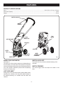
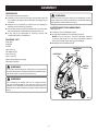
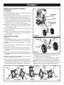
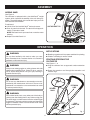
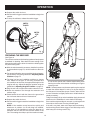
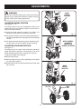
OPERATOR’S MANUAL ELECTRIC CULTIVATOR RY46501B Your electric cultivator has been engineered and manufactured to our high standard for dependability, ease of operation, and operator safety. When properly cared for, it will give you years of rugged, trouble-free performance. WARNING: To reduce the risk of injury, the user must read and understand the operator’s manual before using this product. Thank you for your purchase. SAVE THIS MANUAL FOR FUTURE REFERENCE TABLE OF CONTENTS Introduction ..................................................................................................................................................................... 2 General Safety Rules ....................................................................................................................................................... 3 Specific Safety Rules....................................................................................................................................................... 4 Symbols ........................................................................................................................................................................ 5-6 Electrical .......................................................................................................................................................................... 7 Features ........................................................................................................................................................................... 8 Assembly .................................................................................................................................................................... 9-11 Operation .................................................................................................................................................................. 11-13 Adjustments................................................................................................................................................................... 14 Maintenance .................................................................................................................................................................. 15 Troubleshooting ............................................................................................................................................................. 15 Warranty ........................................................................................................................................................................ 16 Parts Ordering / Servic .................................................................................................................................................. 18 INTRODUCTION This tool has many features for making its use more pleasant and enjoyable. Safety, performance, and dependability have been given top priority in the design of this product making it easy to maintain and operate. 2 GENERAL SAFETY RULES Wear heavy long pants, boots, and gloves. Avoid loose garments or jewelry that could get caught in moving parts of the machine or its motor. WARNING: READ AND UNDERSTAND ALL INSTRUCTIONS. Failure to follow all instructions listed below may result in electric shock, fire, and/or serious personal injury. Do not force tool. Use the correct tool for your application. The correct tool will do the job better and safer at the rate for which it is designed. Do not operate the equipment while barefoot or when wearing sandals or similar lightweight footwear. Wear protective footwear that will protect your feet and improve your footing on slippery surfaces. READ THESE INSTRUCTIONS Read the operator’s manual carefully. Be thoroughly familiar with the controls and the proper use of the equipment. Know how to stop the unit and disengage the controls quickly. Do not operate power tools in explosive atmospheres, such as in the presence of flammable liquids, gases, or dust. Power tools create sparks which may ignite the dust or fumes. To reduce the risk of electric shock, this tool has a polarized plug (one blade is wider than the other) and will require the use of a polarized extension cord. The plug will fit into a polarized extension cord only one way. If the plug does not fit fully into the extension cord, reverse the plug. If the plug still does not fit, obtain a correct polarized extension cord. A polarized extension cord will require the use of a polarized wall outlet. This plug will fit into the polarized wall outlet only one way. If the plug does not fit fully into the wall outlet, reverse the plug. If the plug still does not fit, contact a qualified electrician to install the proper wall outlet. Do not change the equipment plug, extension cord receptacle, or extension cord plug in any way. Avoid body contact with grounded surfaces such as pipes, radiators, ranges, and refrigerators. There is an increased risk of electric shock if your body is grounded. Don’t expose power tools to rain or wet conditions. Water entering a power tool will increase the risk of electric shock. Do not abuse the cord. Never use the cord to carry the tools or pull the plug from an outlet. Keep cord away from heat, oil, sharp edges, or moving parts. Replace damaged cords immediately. Damaged cords increase the risk of electric shock. Secure long hair so it is above shoulder level to prevent entanglement in any moving parts. Do not operate the cultivator while under the influence of alcohol or drugs. Do not put hands or feet near or under tines. Keep firm footing and balance. Do not overreach. Overreaching can result in loss of balance. Avoid accidental starting. Be sure the switch trigger is not engaged before plugging in. Do not carry cultivator with finger on switch trigger. Never pick up or carry a machine while the tines are turning or the motor is running. Keep machine in good working condition. Check all nuts, bolts, and screws at frequent intervals for proper tightness to be sure the equipment is in safe working condition. Keep the unit free of grass, leaves, or grease to reduce the chance of a fire hazard. Do not use tool if switch does not turn it on or off. Any tool that cannot be controlled with the switch is dangerous and must be repaired. Disconnect the plug from power source before making any adjustments, changing accessories, or storing the tool. Such preventive safety measures reduce the risk of starting the tool accidentally. Before cleaning, repairing, or inspecting, unplug the cultivator and make certain all moving parts have stopped. Never spray water directly into the motor compartment of the cultivator. Use outdoor extension cords marked W-A, W, SW-A, SOW-A, STW-A, STOW-A, SJW-A, SJTW-A, or SJTOW-A. These cords are rated for outdoor use and reduce the risk of electric shock. Service on the cultivator must be performed by qualified repair personnel only. Service or maintenance performed by unqualified personnel could result in injury to the user or damage to the product. Never allow children to operate the equipment. Never allow adults to operate the equipment without proper instruction. Use only identical replacement parts when servicing the cultivator. Use of unauthorized parts may create a risk of serious injury to the user, or damage to the product. Always wear safety glasses with side shields. Everyday glasses have only impact resistant lenses. They are NOT safety glasses. Following this rule will reduce the risk of eye injury. Use face mask if operation is dusty. 3 SPECIFIC SAFETY RULES Do not use near underground electric cables, telephone lines, pipes, or hoses. If in doubt, contact your utility or telephone company to locate underground services. Be aware that the equipment may unexpectedly bounce upward or jump forward if the tines should strike buried obstacles such as large stones, roots, or stumps. Make sure your extension cord is in good condition. When using an extension cord, be sure to use one heavy enough to carry the current your product will draw. A wire gauge size (A.W.G.) of at least 14 is recommended for an extension cord 50 feet or less in length. A cord exceeding 100 feet is not recommended. If in doubt, use the next heavier gauge. The smaller the gauge number, the heavier the cord. An undersized cord will cause a drop in line voltage resulting in loss of power and overheating. Never operate the equipment on a slope. Use extreme caution when pulling the machine towards you. When not in use, cultivator should be stored indoors in a dry, locked up place — out of the reach of children. Maintain cultivator with care. Keep tines clean for best performance and reduce the risk of injury. Follow instructions for lubrication and changing accessories. Inspect cultivator cord periodically and, if damaged, have it replaced. Keep handles dry, clean, and free from grease and oil. Start the cultivator carefully according to instructions from a normal operating position and with feet well away from the tines. Do not force cultivator. It will do the job better and with less likelihood of a risk of injury at the rate for which it was designed. Check damaged parts. Before further use of this cultivator, a guard or other part that is damaged should be carefully checked to determine that it will operate properly and perform its intended function. Check for alignment of moving parts, binding of moving parts, breakage of parts, mounting, and any other condition that may affect its operation. A guard or other part that is damaged should be properly repaired or replaced by an authorized service center unless otherwise indicated elsewhere in this manual. Stay alert. Watch what you are doing. Use common sense. Do not operate cultivator when you are tired. If the unit strikes a foreign object, stop the motor, thoroughly inspect the machine for any damage, and repair the damage before restarting and operating the machine. Never leave the operating position when the motor is running. Save these instructions. Refer to them frequently and use them to instruct others who may use this cultivator. If you loan someone this unit, loan them these instructions also. Unplug the unit before unclogging the tines and when making any repairs, adjustments, or inspections. Do not overload the machine capacity by cultivating too deep in a single pass or at too fast a rate. WARNING: Some dust created by power sanding, sawing, grinding, drilling, and other construction activities contains chemicals known to cause cancer, birth defects or other reproductive harm. Some examples of these chemicals are: • lead from lead-based paints, • crystalline silica from bricks and cement and other masonry products, and • arsenic and chromium from chemically-treated lumber. Your risk from these exposures varies, depending on how often you do this type of work. To reduce your exposure to these chemicals: work in a well ventilated area, and work with approved safety equipment, such as those dust masks that are specially designed to filter out microscopic particles. 4 SYMBOLS Some of the following symbols may be used on this tool. Please study them and learn their meaning. Proper interpretation of these symbols will allow you to operate the tool better and safer. SYMBOL NAME DESIGNATION/EXPLANATION V Volts Voltage A Amperes Current Hz Hertz Frequency (cycles per second) W Watt Power Minutes Time Alternating Current Type of current Direct Current Type or a characteristic of current No Load Speed Rotational speed, at no load Class II Construction Double-insulated construction Per Minute Revolutions, strokes, surface speed, orbits etc., per minute Wet Conditions Alert Do not expose to rain or use in damp locations. Read The Operator’s Manual To reduce the risk of injury, user must read and understand operator’s manual before using this product. Eye Protection Always wear safety goggles or safety glasses with side shields and, as necessary, a full face shield when operating this product. Safety Alert Precautions that involve your safety. Keep Bystanders Away Keep all bystanders at least 50 ft. away. Cutting Hazard Keep feet and hands away from rotating tines. Hot Surface To reduce the risk of injury or damage, avoid contact with any hot surface. min no .../min 50' 15 m 5 SYMBOLS The following signal words and meanings are intended to explain the levels of risk associated with this product. SYMBOL SIGNAL MEANING DANGER: Indicates an imminently hazardous situation, which, if not avoided, will result in death or serious injury. WARNING: Indicates a potentially hazardous situation, which, if not avoided, could result in death or serious injury. CAUTION: Indicates a potentially hazardous situation, which, if not avoided, may result in minor or moderate injury. CAUTION: (Without Safety Alert Symbol) Indicates a situation that may result in property damage. SERVICE Servicing requires extreme care and knowledge and should be performed only by a qualified service technician. For service we suggest you return the product to your nearest AUTHORIZED SERVICE CENTER for repair. When servicing, use only identical replacement parts. WARNING: To avoid serious personal injury, do not attempt to use this product until you read thoroughly and understand completely the operator’s manual. If you do not understand the warnings and instructions in the operator’s manual, do not use this product. Call Ryobi customer service for assistance. WARNING: The operation of any power tool can result in foreign objects being thrown into your eyes, which can result in severe eye damage. Before beginning power tool operation, always wear safety goggles or safety glasses with side shields and, when needed, a full face shield. We recommend Wide Vision Safety Mask for use over eyeglasses or standard safety glasses with side shields. Always use eye protection which is marked to comply with ANSI Z87.1. SAVE THESE INSTRUCTIONS 6 ELECTRICAL DOUBLE INSULATION EXTENSION CORDS Double insulation is a concept in safety in electric power tools, which eliminates the need for the usual threewire grounded power cord. All exposed metal parts are isolated from the internal metal motor components with protecting insulation. Double insulated tools do not need to be grounded. When using a power tool at a considerable distance from a power source, be sure to use an extension cord that has the capacity to handle the current the tool will draw. An undersized cord will cause a drop in line voltage, resulting in overheating and loss of power. Use the chart to determine the minimum wire size required in an extension cord. Only round jacketed cords listed by Underwriter’s Laboratories (UL) should be used. When working outdoors with a tool, use an extension cord that is designed for outside use. This type of cord is designated with “WA” on the cord’s jacket. Before using any extension cord, inspect it for loose or exposed wires and cut or worn insulation. WARNING: The double insulated system is intended to protect the user from shock resulting from a break in the tool’s internal insulation. Observe all normal safety precautions to avoid electrical shock. NOTE: Servicing of a tool with double insulation requires extreme care and knowledge of the system and should be performed only by a qualified service technician. For service, we suggest you return the tool to your nearest authorized service center for repair. Always use original factory replacement parts when servicing. **Ampere rating (on tool data plate) 0-2.0 2.1-3.4 Cord Length ELECTRICAL CONNECTION 3.5-5.0 5.1-7.0 7.1-12.0 12.1-16.0 Wire Size (A.W.G.) 25´ 16 16 16 16 14 14 50´ 16 16 16 14 14 12 100´ 16 16 14 12 10 — **Used on 12 gauge - 20 amp circuit. NOTE: AWG = American Wire Gauge This tool has a precision-built electric motor. It should be connected to a power supply that is 120 volts, 60 Hz, AC only (normal household current). Do not operate this tool on direct current (DC). A substantial voltage drop will cause a loss of power and the motor will overheat. If your tool does not operate when plugged into an outlet, double-check the power supply. WARNING: Keep the extension cord clear of the working area. Position the cord so that it will not get caught on lumber, tools, or other obstructions while you are working with a power tool. Failure to do so can result in serious personal injury. GFCI Ground Fault Circuit Interrupter (GFCI) protection should be provided on the circuit(s) or outlet(s) to be used for the cultivator. Receptacles are available having built-in GFCI protection and may be used for this measure of safety. WARNING: Check extension cords before each use. If damaged replace immediately. Never use tool with a damaged cord since touching the damaged area could cause electrical shock resulting in serious injury. 7 FEATURES PRODUCT SPECIFICATIONS Input ..................................................................................................................................... 120 V, 60 Hz, AC only, 12 Amps Sand Tank Capacity ..................................................................................................................................................... 13 lbs. Weight .......................................................................................................................................................................... 32 lbs. SWITCH LOCK-OUT SWITCH TRIGGER JUST ADD SAND™ TINE SHIELD PLUG CONNECTOR DRAG BAR HITCH PIN OUTER TINE WHEEL ASSEMBLY ACCESSORY OUTER TINE INNER TINES Fig. 1 KNOW YOUR CULTIVATOR SWITCH LOCK-OUT See Figure 1. The safe use of this product requires an understanding of the information on the tool and in this operator’s manual as well as a knowledge of the project you are attempting. Before use of this product, familiarize yourself with all operating features and safety rules. The switch lock-out prevents accidental starting of the cultivator. SWITCH TRIGGER The switch trigger starts and stops the rotation of the tines. JUST ADD SAND™ Putting sand in the sand tank allows greater stability when operating the cultivator, and also gives added weight to the machine, allowing it to cultivate with less effort and vibration. 8 ASSEMBLY UNPACKING WARNING: This product requires assembly. Do not connect to power supply until assembly is complete. Failure to comply could result in accidental starting and possible serious personal injury. Carefully remove the tool and any accessories from the box. Make sure that all items listed in the packing list are included. Inspect the tool carefully to make sure no breakage or damage occurred during shipping. Do not discard the packing material until you have carefully inspected and satisfactorily operated the tool. If any parts are damaged or missing, please call 1-800-860-4050 for assistance. POSITIONING THE HANDLEBAR See Figure 2. Loosen the two handlebar knobs. Unfold the handlebar into operating position. NOTE: Do not use force. If there is binding, continue to loosen the knobs. Do not allow the switch cable to become pinched when raising the handlebar. PACKING LIST Cultivator Retighten the handlebar knobs. Drag Bar Pull Pin HANDLEBAR KNOBS Hitch Pins (2) Felt Washers (2) HANDLEBAR Inner Tines (2) Outer Tines (2) Wheel Assembly (Accessory) Operator’s Manual SWITCH CABLE WARNING: If any parts are damaged or missing do not operate this tool until the parts are replaced. Failure to heed this warning could result in serious personal injury. WARNING: Do not attempt to modify this tool or create accessories not recommended for use with this tool. Any such alteration or modification is misuse and could result in a hazardous condition leading to possible serious personal injury. Fig. 2 9 ASSEMBLY INSTALLING THE WHEEL ASSEMBLY ACCESSORY See Figures 3 - 4. Use the wheel assembly accessory to transport the unit to and from the work area. To install: ADJUSTMENT KNOB Raise the adjustment knob located at the back of the tine shield. Twist slightly to secure in the raised position. OPENING Insert the wheel assembly support rod into the opening beneath the adjustment knob. To place the wheels in a high position, insert the rod to the first hole. For a lower wheel position, insert the rod to the second hole. Rotate the adjustment knob in the opposite direction to return it to the seated position, which will secure the wheel assembly in place. Insert the drag bar into the open slot in the wheel assembly support rod. Insert pull pin through holes in support rod, passing through desired hole in drag bar, to secure drag bar at desired height. WHEEL ASSEMBLY SUPPORT ROD DRAG BAR POSITION A INSTALLING THE TINES See Figure 5. The cultivator has four tines —two inner tines labeled B and C, and two outer tines labeled A and D. For correct operation of the unit, the tines must be installed in the correct orientation. WHEEL ASSEMBLY SUPPORT ROD Lean the unit back on its wheels so that the handlebar rests on the ground. DRAG BAR PULL PIN Place tine C on the tine shaft to the left of the gear box. The stamped side of the tine should face away from the gear box. Place tine B on the tine shaft to the right of the gear box. The stamped side of the tine should face away from the gear box. Place a felt washer on each side of the tine shaft, and slide to rest against the inner tines. POSITION B Fig. 4 NOTE: When installed correctly, the angled edge of the tine blades should face the ground. To secure the tines to the tine shaft, insert the hitch pin into the holes located on either side of the tine shaft. NOTE: The unit will not operate properly if the tines are installed incorrectly. If you notice a problem with the cultivating operation of the unit, check for proper tine positioning. Place the outer tine labeled D on the left side of the tine shaft. The stamped side should face in toward tine C. Place the outer tine labeled A on the right side of the tine shaft. The stamped side should face in toward tine B. TINE D Fig. 3 FLAT EDGE FELT WASHER GEAR BOX FELT WASHER TINE A HITCH PIN HITCH PIN ANGLED EDGE TINE C TINE SHAFT 10 TINE B Fig. 5 ASSEMBLY ADDING SAND See Figure 6. The cultivator is equipped with a Just Add Sand™ weight system, which improves the stability of the unit during operation. The added weight of the sand also helps you work with less effort and vibration. To add sand: Lift the lid of the Just Add Sand™ tank and remove. JUST ADD SAND™ LID Pour dry sand into the tank. The tank will hold approximately 13 pounds of sand. NOTE: Be careful not to pour sand into or onto the motor housing. Replace Just Add Sand™ lid. Fig. 6 OPERATION APPLICATIONS WARNING: Breaking up garden soil to prepare seed bed for planting Shallow cultivating to remove weeds Do not allow familiarity with tools to make you careless. Remember that a careless fraction of a second is sufficient to inflict serious injury. STARTING/STOPPING THE CULTIVATOR See Figures 7 - 8. Plug the cultivator into an approved outdoor extension cord. WARNING: Always wear safety goggles or safety glasses with side shields when operating tools. Failure to do so could result in objects being thrown into your eyes, resulting in possible serious injury. Route the extension cord through the extension cord retainer rings. WARNING: Do not use any attachments or accessories not recommended by the manufacturer of this tool. The use of attachments or accessories not recommended can result in serious personal injury. EXTENSION CORD RETAINER RINGS WARNING: Do not allow hands, feet, or any other part of the body or clothing near the rotating tines or any other moving part. The tines begin to rotate forward once the switch trigger is depressed. The tines continue to rotate until the switch trigger is released. Failure to avoid contact could cause serious personal injury. PLUG CONNECTOR Fig. 7 11 OPERATION Depress the switch lock-out. Pull the switch trigger toward the handlebar to begin tine rotation. To stop the cultivator, release the switch trigger. SWITCH TRIGGER 2 1 SWITCH STOP Fig. 8 PREPARING THE SEED BED See Figure 9. The cultivator can be used to break up garden soil and prepare a seedbed for planting. Plan ahead to leave enough room between the seed rows to allow for machine cultivating after the plants have grown. With the wheel assembly accessory installed in position A as described on page 14, roll the machine to the work area. For general cultivating, remove or adjust the wheel assembly accessory using the guidelines in Adjusting Wheel Position on page 14. Fig. 9 The drag bar has two installation positions to choose from. Based on the type of soil being cultivated and soil conditions at the time, the appropriate height of the drag bar will vary. Adjust the drag bar position using the guidelines in Adjusting Drag Bar Position on page 14. so use slower speeds and a shallow depth setting when learning to use the unit and when cultivating on rough or uneven ground. NOTE: Several passes over the same path may be required to reach the desired depth. Do not try to dig too deeply in the first pass. If the machine jumps or bucks, allow the unit to move forward at a slightly faster rate or install wheel assembly accessory. To dig more deeply, lift up on the handlebar. Apply downward pressure on the handlebar for more shallow cultivating. If the machine stays and digs in one spot, try rocking the unit from side to side to start it moving forward again. If the soil is very hard, water a few days before cultivating. Avoid working the soil when soggy or wet. Wait a day or two after heavy rain for the ground to dry. Plug the unit into an approved outdoor extension cord. Route the extension cord through the extension cord retainer rings. Stand behind the unit with the tines on the ground and the work area clean and free of obstructions. Depress the switch lock-out. Pull the switch trigger toward the handlebar to begin tine rotation. NOTE: If the machine moves forward too quickly and wheels are in position A or B with drag bar installed, push down on the handlebar to allow the drag bar to penetrate the soil and slow the forward motion of the unit. The rotating tines help to pull the machine forward, 12 OPERATION GENERAL CULTIVATING See Figure 10. Shallow cultivating less than 2 in. deep can be used to disrupt weeds and aerate soil, without injuring nearby plant roots. It should be done often so that weeds do not grow large and cause tangling in the tines of the unit. The two outer tine blades can be removed from the unit to allow a more narrow cultivating width. To remove the two outer tines: Unplug the cultivator. Remove the hitch pins from the holes on the ends of the tine shaft. Remove the outside tine blades and felt washers from the tine shaft. HITCH PIN Place hitch pins in the holes that were uncovered when felt washers were removed. NOTE: The unit will not operate properly if the tines are installed incorrectly. If you notice a problem with the cultivating operation of the unit, check for proper tine positioning. Fig. 10 13 ADJUSTMENTS WARNING: WHEEL SUPPORT POSITION A To prevent accidental starting that could cause serious personal injury, always disconnect the cultivator from any power source when making adjustments. ADJUSTING WHEEL POSITION See Figures 11 - 13. The wheel position of the unit is adjustable. Holes on the wheel support rod offer different heights to choose from in both the A and B positions. Install the wheel assembly accessory in position A to transport the cultivator to and from the work area. Fig. 11 For general cultivating, remove the wheel assembly to allow deep penetration of the tine blades into the cultivating surface. WHEEL ASSEMBLY ACCESSORY REMOVED FOR GENERAL CULTIVATING The wheel assembly accessory may be installed in position B to allow use of the drag bar during cultivating. ADJUSTING DRAG BAR POSITION See Figure 14. The drag bar may be used to help control the cultivator’s speed and depth of operation. It is located in a slot on the wheel assembly support and is secured with a pull pin. To adjust the height of the drag bar: Remove the pull pin. Fig. 12 Shift the drag bar up or down, depending on the depth you are trying to achieve. Reinsert the pull pin through the wheel support and drag bar to secure. WHEEL SUPPORT POSITION B Fig. 13 PULL PIN DRAG BAR Fig. 14 14 MAINTENANCE Only the parts shown on the parts list are intended to be repaired or replaced by the customer. All other parts should be replaced at an Authorized Service Center. WARNING: When servicing, use only identical replacement parts. Use of any other parts may create a hazard or cause product damage. STORING THE CULTIVATOR The following steps should be taken before storing the cultivator for the season. Clean dirt, grass, and other materials from the entire unit. Wipe the tines with oil or spray them with silicone lubricant to prevent rusting. Oil the switch trigger cable and all visible moving parts. Do not remove the motor cover. WARNING: Always wear safety goggles or safety glasses with side shields during power tool operation or when blowing dust. If operation is dusty, also wear a dust mask. Order new parts to replace any that are badly worn or broken. WARNING: Store in an upright position in a clean, dry place. Store with the handles in the extended position, or loosen handle knobs and fold handles down. Do not allow switch trigger cable to become pinched when lowering the handlebar. Before inspecting, cleaning or servicing the machine, unplug the power cord and wait for all moving parts to stop. Failure to follow these instructions can result in serious personal injury or property damage. PREPARING FOR USE AFTER STORAGE The following steps should be taken before using the cultivator after it has been stored. Unfold the handles into the upright position and secure by tightening handlebar knobs. Do not allow the switch trigger cable to become pinched when raising the handlebar. GENERAL MAINTENANCE Avoid using solvents when cleaning plastic parts. Most plastics are susceptible to damage from various types of commercial solvents and may be damaged by their use. Use clean cloths to remove dirt, dust, oil, grease, etc. Follow the steps on page 11 to restart the cultivator. WARNING: Do not at any time let brake fluids, gasoline, petroleumbased products, penetrating oils, etc., come in contact with plastic parts. Chemicals can damage, weaken or destroy plastic which may result in serious personal injury. TROUBLESHOOTING PROBLEM CAUSE Motor fails to start when switch trigger is depressed. Power cord is not plugged in or connection is loose. Plug in the power cord. Household circuit breaker is tripped. Check circuit breaker. Gear train failure. Take unit to authorized service center. Motor runs but tines do not move. 15 REMEDY WARRANTY LIMITED WARRANTY STATEMENT A. Tune-ups – Spark Plugs, Carburetor, Carburetor Adjustments, Ignition, Filters B. Wear items – Bump Knobs, Outer Spools, Cutting Lines, Inner Reels, Starter Pulleys, Starter Ropes, Drive Belts, Tines, Felt Washers, Hitch Pins, Mulching Blades, Blower Fans, Blower and Vacuum Tubes, Vacuum Bag and Straps, Guide Bars, Saw Chains Techtronic Industries North America, Inc., reserves the right to change or improve the design of any RYOBI® brand outdoor product without assuming any obligation to modify any product previously manufactured. Techtronic Industries North America, Inc., warrants to the original retail purchaser that this RYOBI® brand outdoor product is free from defect in material and workmanship and agrees to repair or replace, at Techtronic Industries North America, Inc.’s, discretion, any defective product free of charge within these time periods from the date of purchase. � Two years if the product is used for personal, family or household use; � 90 days, if used for any other purpose, such as commercial or rental. This warranty extends to the original retail purchaser only and commences on the date of the original retail purchase. Any part of this product found in the reasonable judgment of Techtronic Industries North America, Inc. to be defective in material or workmanship will be repaired or replaced without charge for parts and labor by an authorized service center for RYOBI® brand outdoor products (Authorized Ryobi Service Center). The product, including any defective part, must be returned to an authorized RYOBI service center within the warranty period. The expense of delivering the product to the service center for warranty work and the expense of returning it back to the owner after repair or replacement will be paid by the owner. Techtronic Industries North America, Inc.’s, responsibility in respect to claims is limited to making the required repairs or replacements and no claim of breach of warranty shall be cause for cancellation or rescission of the contract of sale of any RYOBI® brand outdoor product. Proof of purchase will be required by the dealer to substantiate any warranty claim. All warranty work must be performed by an authorized service dealer. This warranty is limited to ninety (90) days from the date of original retail purchase for any RYOBI® brand outdoor product that is used for rental or commercial purposes, or any other income-producing purpose. This warranty does not cover any product that has been subject to misuse, neglect, negligence, or accident, or that has been operated in any way contrary to the operating instructions as specified in this operator’s manual. This warranty does not apply to any damage to the product that is the result of improper maintenance or to any product that has been altered or modified. The warranty does not extend to repairs made necessary by normal wear or by the use of parts or accessories which are either incompatible with the RYOBI® brand outdoor product or adversely affect its operation, performance, or durability. In addition, this warranty does not cover: ALL IMPLIED WARRANTIES ARE LIMITED IN DURATION TO THE STATED WARRANTY PERIOD. ACCORDINGLY, ANY SUCH IMPLIED WARRANTIES INCLUDING MERCHANTABILITY, FITNESS FOR A PARTICULAR PURPOSE, OR OTHERWISE, ARE DISCLAIMED IN THEIR ENTIRETY AFTER THE EXPIRATION OF THE APPROPRIATE TWO-YEAR, ONE-YEAR, OR NINETYDAY WARRANTY PERIOD. TECHTRONIC INDUSTRIES NORTH AMERICA, INC.’S, OBLIGATION UNDER THIS WARRANTY IS STRICTLY AND EXCLUSIVELY LIMITED TO THE REPAIR OR REPLACEMENT OF DEFECTIVE PARTS AND TECHTRONIC INDUSTRIES NORTH AMERICA, INC., DOES NOT ASSUME OR AUTHORIZE ANYONE TO ASSUME FOR THEM ANY OTHER OBLIGATION. SOME STATES DO NOT ALLOW LIMITATIONS ON HOW LONG AN IMPLIED WARRANTY LASTS, SO THE ABOVE LIMITATION MAY NOT APPLY TO YOU. TECHTRONIC INDUSTRIES NORTH AMERICA, INC., ASSUMES NO RESPONSIBILITY FOR INCIDENTAL, CONSEQUENTIAL, OR OTHER DAMAGES INCLUDING, BUT NOT LIMITED TO, EXPENSE OF RETURNING THE PRODUCT TO AN AUTHORIZED RYOBI SERVICE CENTER AND EXPENSE OF DELIVERING IT BACK TO THE OWNER, MECHANIC’S TRAVEL TIME, TELEPHONE OR TELEGRAM CHARGES, RENTAL OF A LIKE PRODUCT DURING THE TIME WARRANTY SERVICE IS BEING PERFORMED, TRAVEL, LOSS OR DAMAGE TO PERSONAL PROPERTY, LOSS OF REVENUE, LOSS OF USE OF THE PRODUCT, LOSS OF TIME, OR INCONVENIENCE. SOME STATES DO NOT ALLOW THE EXCLUSION OR LIMITATION OF INCIDENTAL OR CONSEQUENTIAL DAMAGES, SO THE ABOVE LIMITATION OR EXCLUSION MAY NOT APPLY TO YOU. This warranty gives you specific legal rights, and you may also have other rights which vary from state to state. This warranty applies to all RYOBI® brand outdoor products manufactured by or for Techtronic Industries North America, Inc., and sold in the United States and Canada. To locate your nearest Authorized Ryobi Service Center, dial 1-800-860-4050. 16 NOTES 17 OPERATOR’S MANUAL ELECTRIC CULTIVATOR RY46501B • SERVICE Now that you have purchased your tool, should a need ever exist for repair parts or service, simply contact your nearest Authorized Service Center. Be sure to provide all pertinent facts when you call or visit. Please call 1-800-860-4050 for your nearest Authorized Service Center. You can also check our web site at www.ryobitools.com for a complete list of Authorized Service Centers. • MODEL NO. AND SERIAL NO. The model number of this tool will be found on a plate attached to the housing. Please record the model number and serial number in the space provided below. • HOW TO ORDER REPAIR PARTS When ordering repair parts, always give the following information: • MODEL NUMBER • SERIAL NUMBER RY46501B Ryobi® is a registered trademark of Ryobi® Limited used under license. TECHTRONIC INDUSTRIES NORTH AMERICA, INC. 1428 Pearman Dairy Road Anderson, SC 29625 Phone 1-800-860-4050 www.ryobitools.com 983000-884 12-20-05 (REV:00)