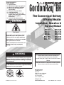
1
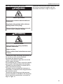
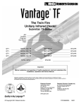
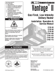
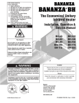
FOR YOUR SAFETY If you smell gas: 1. Open windows. 2. DO NOT try to light any appliance. 3. DO NOT use electrical switches. 4. DO NOT use any telephone in your building. 5. Extinguish any open flame. 6. Leave the building. 7. Immediately call your local gas supplier after leaving the building. Follow the gas supplier’s instructions. 8. If you cannot reach your gas supplier, call the Fire Department. ® GordonRay BH WARNING Fire Hazard Do not store or use gasoline or other flammable vapors and liquids in the vicinity of this or any other appliance. Some objects can catch fire or explode when placed close to heater. The Economical Unitary Infrared Heater Installation, Operation & Service Manual BH-40 BH-60 BH-80 BH-100 BH-115 BH-125 BH-140 BH-150 BH-175 BH-200 Failure to follow these instructions can result in death, injury or property damage. WARNING Improper installation, adjustment, alteration, service or maintenance can result in death, injury or property damage. Read the Installation, Operation and Service Manual thoroughly before installing or servicing this equipment. Installation must be done by a contractor qualified in the installation and service of gas-fired heating equipment or your gas supplier. Installer Please take the time to read and understand these instructions prior to any installation. Installer must give a copy of this manual to the owner. Owner Keep this manual in a safe place in order to provide your serviceman with necessary information. Roberts-Gordon LLC 1250 William Street P.O. Box 44 Buffalo, New York 14240-0044 Telephone: 716.852.4400 Fax: 716.852.0854 Toll Free: 800.828.7450 © 2009 Roberts-Gordon LLC www.rg-inc.com www.radiantheaters.com P/N 170101NA Rev. K 03/09 TABLE OF CONTENTS SECTION 1: Heater Safety...................................................... 1 1.1 Manpower Requirements ............................................. 1 1.2 Safety Labels and Their Placement ............................. 1 SECTION 2: Installer Responsibility ..................................... 3 2.1 Wall Tag ....................................................................... 3 2.2 Corrosive Chemicals.................................................... 3 2.3 National Standards and Applicable Codes .................. 3 SECTION 3: Clearances to Combustibles............................. 4 3.1 Required Clearances to Combustibles......................... 4 SECTION 4: National Standards and Applicable Codes ..... 9 4.1 Gas Codes................................................................... 9 4.2 Aircraft Hangars ........................................................... 9 4.3 Public Garages ............................................................ 9 4.4 Electrical ...................................................................... 9 4.5 Venting......................................................................... 9 4.6 High Altitude ................................................................ 9 SECTION 5: Major Components .......................................... 10 5.1 Standard Parts List .................................................... 11 SECTION 6: Heater Installation............................................ 13 6.1 Burner Tube Installation ............................................ 17 6.2 Tube Clamp Package Installation .............................. 18 6.3 Coupling and Tube Assembly.................................... 18 6.4 Turbulator Installation ................................................ 20 6.5 Reflector Installation .................................................. 21 6.6 Burner Installation...................................................... 23 SECTION 7: Optional Heater Accessories .......................... 24 7.1 U-Tube Configuration.................................................. 24 7.2 Elbow Package Configuration..................................... 27 7.3 Reflector Side Extension ............................................ 30 7.4 Lower Clearance Shield Installation ........................... 31 7.5 Two-Foot Decorative Grille Installation ....................... 31 7.6 Protective Grille Installation ........................................ 33 SECTION 8: Venting.............................................................. 34 8.1 Venting....................................................................... 34 8.2 Unvented Operation................................................... 35 8.3 Horizontal Venting...................................................... 35 8.4 Vertical Venting .......................................................... 35 8.5 Unvented Operation Tube Termination ...................... 35 8.6 Length Requirements ................................................ 35 8.7 Horizontal Ventilation 4'' (10 cm) Pipe ....................... 36 8.8 Vertical Ventilation 4'' (10 cm) Pipe............................ 36 8.9 Common Side Wall Venting ....................................... 37 8.10 Common Vertical Venting ........................................ 38 8.11 Outside Combustion Air Supply ............................... 39 SECTION 9: Gas Piping........................................................ 41 SECTION 10: Wiring.............................................................. 43 10.1 Line Voltage Thermostat Wiring............................... 43 10.2 Low Voltage Thermostat Wiring............................... 44 10.3 Internal Wiring ......................................................... 45 10.4 Ladder Diagram ....................................................... 46 10.5 Electrical Connection to the Burner ......................... 46 SECTION 11: Operation and Maintenance.......................... 47 11.1 Sequence of Operation ............................................ 47 11.2 To Shut Off Heater.................................................... 47 11.3 To Start Heater ......................................................... 47 11.4 Pre-Season Maintenance and Annual Inspection..... 47 11.5 Maintenance Checklist ............................................. 49 SECTION 12: Troubleshooting............................................. 51 12.1 Troubleshooting Flow Chart ..................................... 52 12.2 Manifold Gas Pressure Setting ................................ 54 SECTION 13: Replacement Parts ........................................ 55 SECTION 14: General Specifications .................................. 58 14.1 Material Specifications............................................. 58 14.2 Heater Specifications............................................... 58 14.3 Suspension Specifications....................................... 58 14.4 Controls Specifications ............................................ 58 SECTION 15: The ROBERTS GORDON GORDONRAY BH Warranty ......................................................... 59 ® © 2009 Roberts-Gordon LLC All rights reserved. No part of this work covered by the copyrights herein may be reproduced or copied in any form or by any means - graphic, electronic, or mechanical, including photocopying, recording, taping or information storage and retrieval systems - without the written permission of Roberts-Gordon LLC. Printed in U.S.A. ® TABLE OF FIGURES Figure 1: Top and Bottom Panel Label Placement .................... 1 Figure 2: Side and Back Panel Label Placement ...................... 2 Figure 3: Standard Reflector ..................................................... 5 Figure 4: One Side Reflector..................................................... 5 Figure 5: Two Side Reflectors ................................................... 5 Figure 6: 45° Tilt Reflector ........................................................ 6 Figure 7: U-Tube, Standard Reflector........................................ 6 Figure 8: U-Tube, 45° ................................................................ 6 Figure 9: U-Tube, Opposite 45° Reflector ................................. 7 Figure 10: 2-Foot Deco Grille and Protective Grille ................... 7 Figure 11: Lower Clearance Shield ........................................... 7 Figure 12: Venting ..................................................................... 8 Figure 13: Major Component Descriptions.............................. 10 Figure 14: Critical Hanger Placement ..................................... 14 Figure 15: Linear Heater Assembly Overview ........................ 15 Figure 16: Linear Heater Layout Overview ............................. 16 Figure 17: Linear Heater Layout Overview (Continued) .......... 17 Figure 18: U-Tube Heater Assembly Overview ...................... 25 Figure 19: U-Tube Heater Layout Overview ........................... 26 Figure 20: U-Tube Layout Overview (Continued) .................... 27 Figure 21: Reflector Joint Detail .............................................. 29 Figure 22: Tube Termination ................................................... 35 Figure 23: Gas Connection with Flexible Gas Hose................ 42 LIST OF TABLES Table 1: Contents of BH-Series Burner Carton....................... 11 Table 2: Contents of Core and Extension Packages .............. 11 Table 3: BH-Series Component Package Guide .................... 12 SECTION 1: HEATER SAFETY SECTION 1: HEATER SAFETY Your Safety is Important to Us! This symbol is used throughout the manual to notify you of possible fire, electrical or burn hazards. Please pay special attention when reading and following the warnings in these sections. Installation, service and annual inspection of heater must be done by a contractor qualified in the installation and service of gas-fired heating equipment. Read this manual carefully before installation, operation or service of this equipment. This heater is designed for heating nonresidential indoor spaces. Do not install in residential spaces. These instructions, the layout drawing, local codes and ordinances, and applicable standards that apply to gas piping, electrical wiring, venting, etc. must be thoroughly understood before proceeding with the installation. Protective gear is to be worn during installation, operation and service. Thin sheet metal parts, such as the reflector portion of the heater and the various venting components, have sharp edges. To prevent injury, the use of work gloves is recommended. The use of gloves will also prevent the transfer of body oils from the hands to the surface of the reflector. Before installation, check that local distribution conditions, nature of gas and pressure, and adjustment of the appliance are compatible. For additional copies of the GORDONRAY® BH Installation, Operation and Service Manual, please contact Roberts-Gordon LLC. 1.1 Manpower Requirements To prevent personal injury and damage to the heater, two persons will be required for installation. 1.2 Safety Labels and Their Placement Product safety signs or labels should be replaced by the product user when they are no longer legible. Please contact Roberts-Gordon or your ROBERTS GORDON® independent distributor to obtain replacement signs or labels. See Page 1, Figure 1through Page 2, Figure 2. FIGURE 1: Top and Bottom Panel Label Placement Gas Connection Label Top Panel Vent Length Label Logo Label Description Logo Label Vent Length Label Gas Connection Label Part Number 91031100 91039500 91018123 Bottom Panel 1 BH-SERIES INSTALLATION, OPERATION AND SERVICE MANUAL FIGURE 2: Side and Back Panel Label Placement Side Panel Back Panel Lighting Instruction Plate Label Rating Plate Label BLUE 24VAC BLACK Flame Sense YELLOW Ground BROWN Main Valve Pressure Switch NO Commutateur á C l'air libre BLUE 24VAC Détecteur de flamme JAUNE Terre MARRON Valve principale DSI Ignition Module Module d’allumage par étincelle Electrode Électrode Pressure Switch NO Commutateur á C l'air libre BLUE BLEU NOIR BLUE BLEU BLACK NOIR YELLOW JAUNE Transformer Transformateur BLUE BLEU BLACK NOIR G N WHITE BLANC L2 L BLACK NOIR BH-Series WHITE BLANC WHITE BLANC BROWN MARRON YELLOW JAUNE Transformer Transformateur YELLOW JAUNE YELLOW GREEN JAUNE VERT Gas Valve Valve á gaz GREEN VERT Electrode Électrode BLACK NOIR BROWN MARRON BLEU GREEN VERT BLUE 24VAC BLACK Flame Sense YELLOW Ground BROWN Main Valve BLEU 24VAC NOIR Détecteur de flamme JAUNE Terre MARRON Valve principale BLEU Burner Ground Mise á la terre du brûleur BLACK NOIR G GREEN VERT N WHITE BLANC L2 L BLACK NOIR BH-Series DSI Ignition Module Module d’allumage par étincelle YELLOW JAUNE YELLOW GREEN JAUNE VERT Gas Valve Valve á gaz GREEN VERT Burner Ground Mise á la terre du brûleur Blower Connection Branchement du ventilateur L1 120V-60Hz Electrical Connection Branchement électrique Motor/Blower Moteur/Ventilateur If any of the original wire as supplied with the appliance must be replaced, it must be replaced with wiring material having a temperature rating of at least 105° C and 600 volts. Si une partie du câblage d’origine fourni avec le radiateur doit être remplacée, elle doit l’être par du matériel de câblage tolérant au moins 105°C de température et 600 volts. Printed in the U.S.A/Imprimé aux Etats-Unis P/N 91030301-NA Rev. B Blower Connection Branchement du ventilateur L1 120V-60Hz Electrical Connection Branchement électrique Motor/Blower Moteur/Ventilateur If any of the original wire as supplied with the appliance must be replaced, it must be replaced with wiring material having a temperature rating of at least 105° C and 600 volts. Si une partie du câblage d’origine fourni avec le radiateur doit être remplacée, elle doit l’être par du matériel de câblage tolérant au moins 105°C de température et 600 volts. Printed in the U.S.A/Imprimé aux Etats-Unis Control Door (Inside) Control Side Panel P/N 91030301-NA Rev. B Wiring Label Description Part Number Rating Plate Label 91010401 Lighting Instruction Plate Label 91029602 Wiring Label 91030301 Clearances to Combustibles Label 91013412 Thermostat Connection Label (not shown) 91037902 2 Clearances to Combustibles Label SECTION 2: INSTALLER RESPONSIBILITY SECTION 2: INSTALLER RESPONSIBILITY The installer is responsible for the following: • To install the heater, as well as the gas and electrical supplies, in accordance with applicable specifications and codes. Roberts-Gordon LLC recommends the installer contact a local Building Inspector or Fire Marshal for guidance. • To use the information given in a layout drawing and in the manual together with the cited codes and regulations to perform the installation. • To install the heater in accordance with the clearances to combustibles. • To furnish all needed materials not furnished as standard equipment. • To plan location of supports. • To provide access on all sides for burner servicing and removal. • To provide the owner with a copy of this Installation, Operation and Service Manual. • To never use heater as a support for a ladder or other access equipment and never hang or suspend anything from heater. • To ensure there is adequate air circulation around the heater and to supply air for combustion, ventilation and distribution in accordance with local codes. • To safely and adequately install heater using materials with a minimal working load of 75 lbs (33 kg). • To ensure the heater is placed in an approved application. 2.1 Wall Tag A laminated wall tag is available for the heater as a permanent reminder of the safety instructions and the importance of the required clearances to combustibles. Please contact Roberts-Gordon or your ROBERTS GORDON® independent distributor to obtain the wall tag. Affix the tag by peeling off the backing of the adhesive strips on the rear surface and position the tag on a wall near the heater (e.g. thermostat or ROBERTS GORDON® Controller). A copy of the wall tag (P/N 91037912) is illustrated on the back cover. For an immediate solution, you may affix this copy on the wall near the heater. Know your model number and installed configuration. Model number and installed configuration are found on the burner and in the Installation, Operation and Service Manual. See Page 5, Figure 3 through Page 8, Figure 12. Write the proper clearance dimensions in permanent ink according to your model number and configuration in the open spaces on the tag. 2.2 Corrosive Chemicals CAUTION Product Damage Hazard Do not use heater in area containing corrosive chemicals. Refer to appropriate Material Safety Data Sheets (MSDS). Failure to follow these instructions can result in product damage. Roberts-Gordon LLC cannot be responsible for ensuring that all appropriate safety measures are undertaken prior to installation; this is entirely the responsibility of the installer. It is essential that the contractor, the sub-contractor, or the owner identifies the presence of combustible materials, corrosive chemicals or halogenated hydrocarbons* anywhere in the premises. * Halogenated Hydrocarbons are a family of chemical compounds characterized by the presence of halogen elements (fluorine, chlorine, bromine, etc.). These compounds are frequently used in refrigerants, cleaning agents, solvents, etc. If these compounds enter the air supply of the burner, the life span of the heater components will be greatly reduced. An outside air supply must be provided to the burners whenever the presence of these compounds is suspected. Warranty will be invalid if the heater is exposed to halogenated hydrocarbons. 2.3 National Standards and Applicable Codes All appliances must be installed in accordance with the latest revision of the applicable standards and national codes. This refers also to the electric, gas and venting installation. Note: Additional standards for installations in public garages, aircraft hangars, etc. may be applicable. 3 BH-SERIES INSTALLATION, OPERATION AND SERVICE MANUAL SECTION 3: CLEARANCES TO COMBUSTIBLES 3.1 Required Clearances to Combustibles Clearances are the required distances that combustible objects must be away from the heater to prevent serious fire hazards. Combustibles are materials that may catch on fire and include common items such as wood, paper, rubber, fabric, etc. Maintain clearances to combustibles at all times for safety. Clearances for all heater models are located on the burner of the heater and on Page 5, Figure 3 through Page 8, Figure 12 in this manual. Check the clearances on each burner for the model heater being installed to make sure the product is suitable for your application and the clearances are maintained. Read and follow the safety guidelines below: • Keep gasoline or other combustible materials including flammable objects, liquids, dust or vapors away from this heater or any other appliance. • The stated clearances to combustibles represents a surface temperature of 90° F (32° C) above room temperature. Building materials with a low heat tolerance (such as plastics, vinyl siding, canvas, tri-ply, etc) may be subject to degradation at lower temperatures. It is the installer’s responsibility to assure that adjacent materials are protected from degradation. • Maintain clearances from heat sensitive equipment and workstations. • Maintain clearances from vehicles parked below the heater. • Maintain clearances from swinging and overhead doors, overhead cranes, vehicle lifts, partitions, storage racks, hoists, building construction, etc. • In locations used for the storage of combustible materials, signs must be posted to specify the maximum permissible stacking height to maintain required clearances from the heater to the combustibles. Signs must be posted adjacent to the heater thermostat. In the absence of a thermostat, signs must be posted in a conspicuous location. • Consult local Fire Marshal, Fire Insurance Carrier or other authorities for approval of proposed installation when there is a possibility of exposure to combustible airborne materials or vapors. • Hang heater in accordance to the minimum suspension requirements on Page 14, Figure 14. 4 WARNING Fire Hazard Keep all flammable objects, liquids and vapors the minimum required clearances to combustibles away from heater. Some objects will catch fire or explode when placed close to heater. Failure to follow these instructions can result in death, injury or property damage. • If the radiant tubes must pass through the building structure, be sure that adequate sleeving and fire stop is installed to prevent scorching and/or fire hazard. SECTION 3: CLEARANCES TO COMBUSTIBLES NOTE: 1. All dimensions are from the surfaces of all tubes, couplings and elbows. 2. Clearances B, C and D can be reduced by 50% after 25' (7.5 m) of tubing downstream from where the burner and burner tube connect. FIGURE 3: Standard Reflector Model A (inches) B C BH-40 6 27 52 27 16 69 133 69 BH-60 6 35 62 35 16 89 158 89 BH-80 6 38 65 38 16 97 166 97 BH-100 6 40 70 40 16 102 178 102 BH-115/125 6 46 76 46 16 117 194 117 BH-140/150 6 50 79 50 16 127 201 127 BH-175/200 8 52 82 52 21 133 209 133 Model A (inches) B C D A BH-40 6 9 52 44 16 23 133 112 BH-60 6 9 62 47 16 23 158 120 BH-80 6 9 69 54 16 23 176 138 BH-100 6 9 76 59 16 23 194 150 BH-115/125 6 9 82 65 16 23 209 166 BH-140/150 6 9 85 69 16 23 216 176 BH-175/200 8 9 88 73 21 23 224 186 Model A (inches) B C D A BH-40 6 15 52 15 16 39 133 39 BH-60 6 23 65 23 16 59 166 59 BH-80 6 25 71 25 16 64 181 64 BH-100 6 27 77 27 16 69 196 69 BH-115/125 6 32 83 32 16 82 211 82 BH-140/150 6 35 87 35 16 89 221 89 BH-175/200 8 40 91 40 21 102 232 102 D A (centimeters) B C D FIGURE 4: One Side Reflector A B D C (centimeters) B C D FIGURE 5: Two Side Reflectors A B D C (centimeters) B C D 5 BH-SERIES INSTALLATION, OPERATION AND SERVICE MANUAL NOTE: 1. All dimensions are from the surfaces of all tubes, couplings and elbows. 2. Clearances B, C and D can be reduced by 50% after 25' (7.5 m) of tubing downstream from where the burner and burner tube connect. FIGURE 6: 45° Tilt Reflector Model A (inches) B C BH-40 8 8 50 46 21 21 127 117 BH-60 8 8 59 54 21 21 150 138 BH-80 8 8 65 60 21 21 166 153 BH-100 10 8 73 64 26 21 186 163 BH-115/125 10 8 77 69 26 21 196 176 BH-140/150 12 8 83 74 31 21 211 188 BH-175/200 12 8 85 79 31 21 216 201 D A (centimeters) B C D FIGURE 7: U-Tube, Standard Reflector BH-40 (inches) A B C D - UNAPPROVED - (centimeters) A B C D - UNAPPROVED - BH-60 6 35 62 30 16 89 158 77 BH-80 6 38 68 37 16 97 173 94 BH-100 6 40 75 39 16 102 191 100 BH-115/125 6 46 78 43 16 117 199 110 BH-140/150 6 50 83 47 16 127 211 120 BH-175/200 8 54 87 51 21 138 221 130 Model A C B D FIGURE 8: U-Tube, 45° A C 6 (centimeters) A B C D - UNAPPROVED - BH-60 8 8 59 42 21 21 150 107 BH-80 8 8 65 46 21 21 166 117 BH-100 8 8 73 52 21 21 186 133 BH-115/125 8 8 77 61 21 21 196 155 BH-140/150 8 8 83 66 21 21 211 168 BH-175/200 8 8 85 70 21 21 216 178 Model D B BH-40 (inches) A B C D - UNAPPROVED - SECTION 3: CLEARANCES TO COMBUSTIBLES NOTE: 1. All dimensions are from the surfaces of all tubes, couplings and elbows. 2. Clearances B, C and D can be reduced by 50% after 25' (7.5 m) of tubing downstream from where the burner and burner tube connect. FIGURE 9: U-Tube, Opposite 45° Reflector BH-40 (inches) A B C D - UNAPPROVED - (centimeters) A B C D - UNAPPROVED - BH-60 8 54 59 22 21 138 150 56 BH-80 8 60 65 22 21 153 166 56 BH-100 10 64 73 22 26 163 186 56 BH-115/125 10 70 77 22 26 178 196 56 BH-140/150 12 74 83 22 31 188 211 56 BH-175/200 12 76 85 22 31 194 216 56 Model A B D C FIGURE 10: 2-Foot Deco Grille and Protective Grille A C B D Model A (inches) B C BH-40 6 27 52 27 16 69 133 69 BH-60 6 35 62 35 16 89 158 89 BH-80 6 38 65 38 16 97 166 97 BH-100 6 40 70 40 16 102 178 102 BH-115/125 6 46 76 46 16 117 194 117 BH-140/150 6 50 79 50 16 127 201 127 BH-175/200 8 52 82 52 21 133 209 133 Model A (inches) B C D A BH-40 6 34 27 34 16 87 69 87 BH-60 6 39 33 39 16 100 84 100 BH-80 6 40 38 40 16 102 97 102 BH-100 6 50 44 50 16 127 112 127 BH-115/125 6 54 48 54 16 138 122 138 BH-140/150 6 55 50 55 16 140 127 140 D A (centimeters) B C D FIGURE 11: Lower Clearance Shield* A B D C BH-175/200 - UNAPPROVED - (centimeters) B C D - UNAPPROVED - *When installed in the first 10' (3 m). 7 BH-SERIES INSTALLATION, OPERATION AND SERVICE MANUAL NOTE: 1. All dimensions are from the surfaces of all tubes, couplings and elbows. 2. Clearances B, C and D can be reduced by 50% after 25' (7.5 m) of tubing downstream from where the burner and burner tube connect. FIGURE 12: Venting A Unvented Radiant Tubes Vented 8 E Vent Pipes F Model A (inches) E F (centimeters) A E F BH-40 14 18 18 36 46 46 BH-60 14 18 18 36 46 46 BH-80 20 24 18 51 61 46 BH-100 20 24 18 51 61 46 BH-115/125 20 24 18 51 61 46 BH-140/150 20 30 18 51 77 46 BH-175/200 20 30 18 51 77 46 SECTION 4: NATIONAL STANDARDS AND APPLICABLE CODES SECTION 4: NATIONAL STANDARDS AND APPLICABLE CODES 4.1 Gas Codes The type of gas appearing on the nameplate must be the type of gas used. Installation must comply with national and local codes and requirements of the local gas company. United States: Refer to National Fuel Gas Code NFPA 54/ANSI Z223.1 - latest revision. Canada: Refer to Natural Gas and Propane Installation Code CSA B149.1 - latest revision. 4.2 Aircraft Hangars Installation in aircraft hangars must be in accordance with the following codes: United States: Refer to Standard for Aircraft Hangars, NFPA 409 - latest revision. Canada: Refer to Natural Gas and Propane Installation Code CSA B149.1 - latest revision. In aircraft storage and servicing areas, heaters shall be installed at least 10' (3 m) above the upper surface of wings or of engine enclosures of the highest aircraft which may be housed in the hangar. The measurement shall be made from the wing or engine enclosure (whichever is higher from the floor) to the bottom of the heater. • In shops, offices and other sections of aircraft hangars communicating with aircraft storage or servicing areas, heaters shall be installed not less than 8' (2.4 m) above the floor. • Suspended or elevated heaters shall be so located in all spaces of aircraft hangars that they shall not be subject to injury by aircraft, cranes, movable scaffolding or other objects. Provisions shall be made to assure accessibility to suspended heaters for recurrent maintenance purposes. 4.3 Public Garages Installation in garages must be in accordance with the following codes: United States: Refer to Standard for Parking Structures NFPA 88A - latest revision or the Code for Motor Fuel Dispensing Facilities and Repair Garages, NFPA 30A - latest revision. Canada: Refer to Natural Gas and Propane Installation Code CSA B149.1 - latest revision. • Heaters must not be installed less than 8' (2.4 m) above the floor. Minimum clearances to combustibles must be maintained from vehicles parked below the heater. • When installed over hoists, minimum clearances to combustibles must be maintained from the upper most point of objects on the hoist. 4.4 Electrical The heater must be electrically grounded in accordance with the following codes: United States: Refer to National Electrical Code®, NFPA 70 - latest revision. Wiring must conform to the most current National Electrical Code®, local ordinances and any special diagrams furnished. Canada: Refer to Canadian Electrical Code, CSA C22.1 Part 1 - latest revision. 4.5 Venting The venting must be installed in accordance with the requirements within this manual and the following codes: United States: Refer to National Fuel Gas Code NFPA 54/ANSI Z223.1 - latest revision. Canada: Refer to Natural Gas and Propane Installation Code CSA B149.1 - latest revision. 4.6 High Altitude These heaters are approved for installations up to 2000' (610 m)(US), 4500' (1370 m)(Canada) without modification. Consult factory if US installation is above 2000' (610 m) or Canadian installation is above 4500' (1370 m). 9 BH-SERIES INSTALLATION, OPERATION AND SERVICE MANUAL SECTION 5: MAJOR COMPONENTS FIGURE 13: Major Component Descriptions Burner with Tube Gasket Must be installed with the flame observation window facing down. Reflector (Aluminum or Stainless Steel) Alternate overlap as shown on overview and on Page 16, Figure 16. Minimum overlap is 6'' (16 cm). Burner Tube Supplied in 10' (3 m) lengths. Burner tube is always the first tube after the burner. Tube Hot rolled or heat treated aluminized tube supplied in 10' (3 m) lengths. Tube and Reflector Hanger with Clamp Package Position this hanger no more than 4” (10 cm) away from the burner. Coupling Assembly with Lock Reflector End Cap Punch out center section to accommodate tube. Tube and Reflector Hanger Suspend system from these hangers. Vent Adapter Reflector Support Strap & Wire Form Flex Gas Line with Shut Off Cock 10 Turbulator Turbulator must be installed in the last standard section of tube. Turbulator is not required on the BH-125/150/175/200. For installation, see Page 20, Step 6.4 SECTION 5: MAJOR COMPONENTS 5.1 Standard Parts List Table 1: Contents of BH-Series Burner Carton Part No. Description BH-40 BH-60 BH-80 BH-100 BH-115 BH-125 BH-140 BH-150 BH-175 BH-200 071XXXXX Burner (Rate and Fuel Varies) 1 1 1 1 1 1 1 1 1 1 90709700 Blower Assembly with Cord 1 1 1 1 1 1 1 1 1 1 02568200 Gasket (Burner to Burner Tube) 1 1 1 1 1 1 1 1 1 1 90709801 Gasket (Blower to Burner) 1 1 1 1 1 1 1 1 1 1 170101NA Installation, Operation and Service Manual 1 1 1 1 1 1 1 1 1 1 91201708 Pipe Nipple (Black) 1/2" NPT x 4" 1 1 1 1 1 1 1 1 1 1 94273914 Hex Head Bolts 5/16" - 18 Rolok 4 4 4 4 4 4 4 4 4 4 96411600 Split Lock Washer 4 4 4 4 4 4 4 4 4 4 *91412200 Flexible Stainless Steel Gas Hose, 1/2" NPT (US Models Only) 1 1 1 1 1 1 - - - - *91412204 Flexible Stainless Steel Gas Hose, 3/4" NPT (US Models Only) - - - - - - 1 1 1 1 91907302 S-Hooks 2 2 2 2 2 2 2 2 2 2 91911700 Outside Air Collar 1 1 1 1 1 1 1 1 1 1 94118106 #8 x 3/8 Hex Washer Head (for Outside Air Collar) 3 3 3 3 3 3 3 3 3 3 92311800 Keps Nut 4 4 4 4 4 4 4 4 4 4 03051503 Turbulator Adapter 1 1 1 1 1 - 1 - - - 03051504 Turbulator 2.5' (76 cm), Aluminized Steel 2 4 4 1 3 - 1 - - - 03051505 Turbulator 2.5' (76 cm), Stainless Steel 1 - - - - - - - - - *Canadian models: Rubber (Type 1) Gas Hoses available as an accessory. See Page 41. Table 2: Contents of Core and Extension Packages Core Packages Hot Rolled Part No. Description Extension Packages Aluminized Hot Rolled Aluminized 20' 30' 40' 10' 20' 30' 40' 10' 20' 30' 40' 10' 20' 30' 40' (6m) (9m) (12m) 91409300 Tube, Hot Rolled Steel, 10' (3 m) 1 2 3 - - 91409408 Tube, HT Aluminized, 10' (3 m) - - - - 1 03051101 Burner Tube, ALUMI-THERM Steel, 10' (3 m) - 1 1 - - 1 03051601 Burner Tube, HT ALUMI-THERM Steel, 10' (3 m) 1 - - 1 1 - - - - - - - - - - 01312700 Coupling Assembly 1 2 3 - 1 2 3 1 2 3 4 1 2 3 4 02750303 Standard Reflector, 8' (3.5 m) 3 4 6 2 3 4 6 2 3 4 6 2 3 4 6 02750800 End Cap 2 2 2 2 2 2 2 - - - - - - - - 03090100 Tube and Reflector Hanger 3 4 5 2 3 4 5 1 2 3 4 1 2 3 4 ® 2 3 4 - - - - - - - - 1 2 3 4 1 - - - - - - - - 91907302 S-Hook 3 4 5 2 3 4 5 1 2 3 4 1 2 3 4 03050010 Reflector Support Package (Strap, Wire Form, Screws) 2 3 5 1 2 3 5 2 3 4 6 2 3 4 6 91107720 U-Clip Package 1 1 1 1 1 1 1 1 1 1 1 1 1 1 1 90502700 Vent Adapter 1 1 1 1 1 1 1 - - - - - - - - 1 1 1 1 1 1 1 - - - - - - - EXP40ALUM 1 EXP30ALUM 3 EXP20ALUM 2 EXP10ALUM (12m) EXP40HRS (9m) EXP30HRS (6m) EXP20HRS (3m) EXP10HRS (12m) CP40ALUM (9m) CP30ALUM (6m) CP20ALUM (3m) CP10ALUM (12m) CP40HRS (9m) CP30HRS (6m) CP20HRS ® (3m) 01318901 Tube Clamp Package Part Number 11 BH-SERIES INSTALLATION, OPERATION AND SERVICE MANUAL Table 3: BH-Series Component Package Guide Model Tubing Length Core Packages Minimum Standard Aluminized BH-40 10' (3 m) - CP10ALUM BH-60 20' (6 m) CP20HRS CP20ALUM BH-80 20' (6 m) CP20HRS CP20ALUM BH-100 30' (9 m) CP30HRS CP30ALUM BH-115 30' (9 m) CP30HRS CP30ALUM BH-125 40' (12 m) CP40HRS CP40ALUM BH-140 40' (12 m) CP40HRS CP40ALUM BH-150 50' (15 m) CP30HRS + EXP20HRS CP30ALUM + EXP20ALUM BH-175 50' (15 m) CP30HRS + EXP20HRS CP30ALUM + EXP20ALUM BH-200 60' (18 m) CP30HRS + EXP30HRS CP30ALUM + EXP30ALUM Additional tubing length may be added to heater. Tubing must be heat-treated, aluminized or porcelain coated. Any additional tubing lengths are considered as vent length for length determination. Maximum venting length for minimum heater length is 45' (13.7 m) total. 12 SECTION 6: HEATER INSTALLATION SECTION 6: HEATER INSTALLATION WARNING Expansion and contraction of the tube dictates that the minimum suspension lengths must be maintained. See table on Page 14, Figure 14. Severe Injury Hazard Secure burner to burner tube with bolts and lockwashers. Hang heater with materials with a minimum working load of 75 lbs (33 kg). Failure to follow these instructions can result in death, injury or property damage. WARNING Cut/Pinch Hazard Wear protective gear during installation, operation and service. Edges are sharp. Failure to follow these instructions can result in injury. To ensure your safety and comply with the terms of the warranty, all units must be installed in accordance with these instructions. The gas or the electrical supply lines must not be used to support the heater. Do not locate the gas or electric supply lines directly over the path of the flue products from the heater. The heater must be installed in a location that it is readily accessible for servicing. The heaters must be installed with clearances to combustibles as indicated on the rating plate and in this instruction manual. The minimum and maximum gas inlet pressures must be maintained as indicated on the rating plate. Typical installation configurations are shown on Page 14, Figure 14. 13 BH-SERIES INSTALLATION, OPERATION AND SERVICE MANUAL FIGURE 14: Critical Hanger Placement Typical Suspension Details Beam Clamp Anchor Screw Hook 3/8" 24" min.* (61 cm) Chain Size 3/16" Minimum Rod 3/8" Concrete Beam Wood Beam Locknut Washers X* S-hooks Turnbuckle Not Included * Allows for thermal expansion of system S-hooks Hanger Side View Hanger Reflector Must Be Within 4" (10 cm) Description S-Hook Tube/Reflector Hanger 14 Part Number 91907302 03090100 Front View Run Length 10' (3 m) - 50' (15.2 m) 51' (15.5 m) - 60' (18.3 m) 61' (18.6 m) - 80' (24.4 m) 45° Angle Typical Expansion ±1" (3 cm) ±2" (5 cm) ±3" (8 cm) Minimum “X” Length 12" (30.5 cm) 18" (45.7 cm) 24" (61 cm)