1
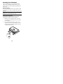
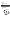
393/394
Sensitometer
Operation Manual
FCC
This equipment has been tested and found to comply
with the limits for a Class A digital device, pursuant to
Part 15 of the FCC Rules. These limits are designed to
provide reasonable protection against harmful
interference when the equipment is operated in a
commercial environment. This equipment generates,
uses, and can radiate radio frequency energy and, if not
installed and used in accordance with the instruction
manual, may cause harmful interference to radio
communications. Operation of this equipment in a
residential area is likely to cause harmful interference in
which case the user will be required to correct the
interference at his own expense.
Canada
This digital apparatus does not exceed the Class A limits
for radio noise emissions from digital apparatus set out in
the Radio Interference Regulations of the Canadian
Department of Communications.
Le present appareil numerique n'emet pas de bruits
radioelectriques depassant les limites applicables aux
appareils numeriques de la class A prescrites dans le
Reglement sur le brouillage radioelectrique edicte par le
ministere des Communications du Canada.
CAUTION: Reverse connection of battery may cause
damage to circuit. Use only 9-volt alkaline batteries.
VORSICHT: Eine umgekehrte Verbindung zur Akku
könnte die Schaltung beschädigen. Verwenden Sie nur
9 Volt- Alkalibatterien.
ADVERTENCIA: Conexión inversa de las pilas
causaría daño al circuito. Use solamente las pilas
alcalinas de 9 voltios.
ATTENTION: Un raccordement inversé des piles peut
endommager le circuit. Utiliser seulement des piles fernickel de 9 volts.
AVVERTIMENTO: Connesione inversa delle pile può
causare danno al circuito. Usare solamente le pile
alcaline di 9 volt.
i
CE DECLARATION
Manufacturer’s Name
Manufacturer’s Address:
X-Rite, Incorporated
3100 44th Street, S.W.
Grandville, Michigan
49418 U.S.A.
Model Name:
Model No.:
Sensitometer
393 and 394
Directive(s) Conformance:
EMC 89/336/EEC
WARNING
This is a class A product. In a domestic environment this
product may cause radio interference in which case the
user may be required to take adequate measures.
Proprietary Notice
The information contained in this manual is derived
from patent and proprietary data of X-Rite,
Incorporated. This manual has been prepared solely for
the purpose of assisting in the use and general
maintenance of this instrument.
The contents of this manual are the property of X-Rite,
Incorporated and are copyrighted. Any reproduction in
whole or part is strictly prohibited. Publication of this
information does not imply any rights to reproduce or
use this manual for any purpose other than installing,
operating, or maintaining this instrument. No part of
this manual may be reproduced, transcribed,
transmitted, stored in a retrieval system, or translated
into any language or computer language, in any form or
by any means, electronic, magnetic, mechanical,
optical, manual, or otherwise, without the prior written
permission of an officer of X-Rite, Incorporated.
©2002 by X-Rite, Incorporated. “ALL RIGHTS RESERVED”
ii
Limited Warranty
X-Rite, Incorporated warrants each unit manufactured
to be free of defects in material and workmanship for a
period of twelve months. If the fault has been caused by
misuse or abnormal conditions of operations, repairs
will be billed at a nominal cost. In this case, an estimate
will be submitted before work is started, if requested.
The unit shall be returned with transportation charges
prepaid.
There are no warranties of merchantability or
fitness. This warranty obligation is limited to
servicing the unit returned to X-Rite, Incorporated
or an authorized dealer for that purpose.
X-Rite, Incorporated offers a repair program for
instruments out of original warranty coverage. For more
information, contact X-Rite Customer Service at:
1-888-826-3044.
Always include serial number in any correspondence
concerning the unit. The serial number is located on the
bottom of the instrument.
This agreement shall be interpreted in accordance with
the laws of the State of Michigan and jurisdiction and
venue shall lie with the courts of Michigan as selected
by X-Rite, Incorporated.
iii
Table Of Contents
1. Getting Started ...................................... 1
Unpacking and Inspection ..................... 1
Instrument Description........................... 2
Applying Power...................................... 3
2. Application and Procedures................. 4
Sensitometer Monitoring For Process
Control ................................................... 4
Processing Procedure ........................... 6
Manual Data Recording Procedure........ 7
Automatic Data Recording Procedure—
Using the 391 Densitometer .................. 9
Processor Troubleshooting.................. 10
3. Using the Sensitometer ...................... 11
Setting Exposure Color........................ 11
Selecting Single or Dual Exposure
(394 only)............................................. 12
Adjusting Exposure Setting (393) ........ 12
Adjusting Exposure Setting (394) ........ 13
Exposing Film ...................................... 14
4. General Maintenance .......................... 16
Repair Information ............................... 16
Calibration/Recertification.................... 16
Cleaning the Instrument....................... 17
Replacing the Battery .......................... 18
5. Technical Specifications .................... 19
iv
1. Getting Started
Unpacking and Inspection
After removing the instrument from the shipping carton,
inspect for possible damage. If any damage has
occurred during shipping, immediately contact the
transportation company. Do not proceed with
installation until the carrier’s agent has inspected the
damage.
If damage is not evident, check to make sure that the
following items are included:
•
•
•
•
•
Sensitometer (393 or 394)
Operation Manual (this document)
Certificate of Calibration
Registration Card
Important Notice
Your instrument was packaged in a specially designed
carton to assure against damage. If reshipment is
necessary, the instrument should be packaged in the
original carton. If the original carton is not available,
contact X-Rite at: 1-888-826-3044 to have a
replacement shipped to you.
1
Instrument Description
The Process Optimization Sensitometer is a battery
operated, dual color, single or dual (394 only) sided
exposure sensitometer, designed for quality control of
cine and X-ray processing systems. It produces a
repeatable stepped exposure on applicable film.
Its ease of operation enables anyone with little
instruction to expose repeatable sensitomerty strips,
with either blue or green exposing light—simulating the
light from blue and green intensifying screens.
Advanced low-power circuitry allows a long battery life
without sacrificing performance. Replacement battery is
a “9 Volt” alkaline type.
Exposure Button
Single/Dual Exposure Switch (394)
Power Switch (393)
Color Switch
2
Applying Power
The sensitometer is shipped from the factory with the
battery installed and power switch in the “Off” (left)
position—slide switch to the “On” (right) position. The
battery switch for the 393 is located on the front of the
instrument. The battery switch for the 394 is located on
the bottom of the instrument.
Because there is no drain on the battery during non-use
times, the power switch can remain in the “On”
position. The only time that the power switch must be
turned “Off” is when the instrument is transported or
the battery replaced.
Your sensitometer is designed to operate from a “9
Volt” alkaline battery for approximately one year.
When the battery is low, the circuit will not allow any
exposures to occur. Should your unit become
inoperative, replace the battery first, refer to Section
Five. If this does not rectify the problem, refer the
instrument to X-Rite or an authorized service center for
proper servicing. There are no user serviceable
components in the sensitometer.
3
2. Application and
Procedures
Sensitometer Monitoring For
Process Control
The sensitometer exposes film with a known quantity of
light through a 21-step light modulator. The maximum
light is emitted from Step No. 21. Each successive step
emits approximately 70.7% of the light emitted from the
step adjacent to it (.15 log exposure). The processed
film responds to this exposure in a predictable manner.
A plot of optical density—measured on the processed
film—against relative log exposure values is known as
the D-Log E curve. Figure One shows the response of a
typical radiographic film to exposure with the
sensitometer. The portion of the curve that changes
most with variations in processing is called the “straight
line portion” of the curve.
It is not necessary to plot D-Log E Curves to monitor
automatic processors in normal laboratory
environments. A simpler method is to record the three
parameters from the D-Log E Curve which contain
most of the data.
The following three parameters on the curve should be
monitored to give pertinent processing data.
•
•
Base+Fog: Step No. 1 on the D-Log E Curve is
called Base+Fog the least exposed portion of the
film. It is the base support density plus any silver
emulsion density developed in the area where
negligible exposure should occur.
Speed Index: The step on the exposed film with a
density nearest 1.OD+ Base+Fog is called Speed
Index. This step is a direct indicator of film speed.
4
Variations in processor conditions are monitored
on this step.
•
Contrast Index: An indicator of the slope of the
straight-line portion of the D-Log E Curve is
called Contrast Index. Select the step closest to
but not larger than 2.20D. Subtract from this step
the step closest to but not lower then 0.45D.
Contrast Index is used to monitor processor
variations in conjunction with the Speed Index.
FIGURE 1. D-Log E Curve
Optical density versus relative log exposure for typical
radiographic film.
SPEED INDEX
CONTRAST INDEX
BASE+FOG
Selection and Use of Film
5
The film selected to monitor a given processor should
be representative of the film used with that processor.
Scheduling Sensitometric Control
Every processor in use should have a separate control
chart plotted to monitor its behavior. The more frequent
the data points, the better the control feedback. A
control film should be run at start-up of the processor
and at least once a day. Use sensitometry whenever
trouble is suspected, or a change has been made to the
process.
Processing Procedure
1.
Allow the processor
temperature and
chemistry to reach
equilibrium when starting
up the processor before
processing film.
X-Rite
1
2
3
4
5
2.
Films should be processed
immediately after being
exposed. Any delay
between exposure and
processing should be
consistent from film to
film.
3.
Run a full width film for
cleanup at start-up.
4.
Orient the film into the
processor in a consistent
manner— making sure the
film is inserted per
processor manufacturer's
specification.
6
6
7
8
9
10
11
12
13
14
15
16
17
18
19
20
21
TIME:
DATE:
ID NO:
5.
After processing of film is complete, record the
date, time, and processor identification number on
the film in the designated areas.
Manual Data Recording
Procedure
Establishing Normal Speed Index, Contrast
Index, and Base+Fog
The normal speed index, contrast index, and base+fog
values are established on a representative film, when
the processor is considered to be operating in an
optimum fashion.
Run several film samples and determine the average
values for speed index, contrast index, and base+fog,
using a transmission densitometer. Step wedge areas are
as uniform as is possible to produce. There are,
however, some errors at the edges of the step area.
Therefore, always measure density at the center of
the step. Use a 2mm aperture to give best repeatability.
Record the following data on the process control
record.
•
•
•
•
Developer Temperature - Temperature of
developer solution in processor during processing
Normal Base+Fog - Step number one density, the
least exposed step on the wedge.
Normal Speed Index - The density of the step
closest to 1.0D + base+fog. The step number
should remain the same for a given processor and
film type.
Normal Contrast Index - Select the step closest
to but not larger than 2.20D. Subtract from this
step the step closest to but not lower than 0.45D.
7
NOTE: Monitor subsequent films on the same steps
selected for normal contrast index.
•
•
•
•
•
•
•
•
•
•
Date - Month - Day – Year
Processor Number - Processor identification
Emulsion Number - Film batch identification
Developer Type - Developer vendor
identification
Fixer Type - Fixer vendor identification
Film Type - Film vendor identification
Exposure Color - Exposure light (blue or green)
Developer Replenisher Rate - The rate of
developer replenishment
Fixer Replenisher Rate - The rate of fixer
replenishment
Processing Time - Film process time, input-tooutput
A box of film should be set aside from regular stock for
exclusive sensitometer use. New film stock will require
re-establishment of normal values because small density
changes are possible between film batches.
Daily Plotting of Data on Process Control
Record
Plot the Speed Index, Contrast Index, Base+Fog, and
Developer Temperature results on the process control
record each time a control film is developed. Record
data immediately so that it is not lost or changed.
8
Automatic Data Recording
Procedure—Using the 391
Densitometer
When the X-Rite 391 densitometer is used to measure
process control films, it will automatically calculate and
store the values for: speed index, contrast index, and
base+fog. The unit will also store up to 32
measurements of film data for twelve processors.
Printing Process Control Records
The 391 densitometer will printout the process control
record when interfaced to a printer (see below).
9
Processor Troubleshooting
When troubleshooting out of tolerance processor
conditions, use Speed Index as the primary guide.
Speed Index is the most predictable indicator for all
film types. Base+Fog is predictable, but is the least
sensitive. Contrast Index reacts predictably for a given
set of film conditions but may vary from film to film.
Listed below is a chart showing Speed Index and
Base+Fog reactions to common processor problem
conditions.
As Control Records become more complete for a given
film, the relationships between Contrast Index and
Processor Conditions will become apparent. Always
note the reason for out-of-tolerance processor condition
on the Control Record.
NOTE: When out-of-tolerance conditions are noticed,
always verify results with another test film before
making any processor adjustments.
Speed Index
Base+Fog
Possible Cause
High
High or
Normal
Developer
temperature too high.
Developer over
replenished.
Improper safe lighting.
Improper solution mix.
Low
Low or
Normal
Developer
temperature too low.
Developer under
replenished.
Inadequate developer
circulation.
Improper solution mix.
Contaminated
developer.
10
3. Using the Sensitometer
Setting Exposure Color
Optimum sensitometric control occurs when the proper
color light exposes the film. Expose with the same color
emitted from the intensifying screen recommended by
the film manufacturer for the film being exposed. For
example, when using blue emitting intensifying
screen—expose in “BLUE” position. Slide the color
switch on the front of the unit to the left for “BLUE” or
to the right for “GREEN.”
NOTE: The exposure time should be set in accordance
with the manufacturers requirements. See Adjusting
Exposure Setting on the following pages.
11
Selecting Single or Dual
Exposure (394 only)
Depending on the type of film that is to be exposed, the
sensitometer can have either single sided or doublesided exposure selected.
If the film to be exposed is a single emulsion type, slide
the exposure switch to the “SINGLE” position and
expose Emulsion Side Down. Expose double emulsion
type films in the “DUAL” switch position.
Adjusting Exposure Setting (393)
The sensitometer has the capability of seven different
exposure times for both blue and green. The factory
preset exposure setting is #3. If different exposure times
are required, refer to the chart on the next page—or
bottom of unit—for the settings. Each exposure setting
will move the speed index on the film one step.
The dipswitch used to change the exposure time is
located on the bottom of the unit. When the blue color
is selected, switches A,B,C,D bracketed as blue are
12
activated. When the green color is selected, switches
A,B,C,D bracketed as green are activated.
Exposure Setting
1
MIN
2
3
4
5
6
7
MAX
A
OFF
ON
OFF
OFF
ON
OFF
OFF
B
OFF
OFF
ON
OFF
ON
OFF
OFF
C
OFF
OFF
OFF
ON
ON
OFF
ON
D
OFF
OFF
OFF
OFF
OFF
ON
ON
Adjusting Exposure Setting (394)
The sensitometer has the capability of seven different
exposure times for both single and dual. The factory
preset exposure setting is “3” for both single and dual.
If different exposure times are required, refer to the
chart below—or bottom of unit—for the settings. Each
exposure setting will move the speed index on the film
one step.
The dipswitch used to change the exposure time is
located on the bottom of the unit. When single emulsion
is selected, switches A,B,C,D bracketed as “SINGLE”
are activated. When the dual emulsion is selected,
switches A,B,C,D bracketed as “DUAL” are activated.
Exposure Setting
1
MIN
2
3
4
5
6
7
MAX
A
OFF
ON
OFF
OFF
ON
OFF
OFF
13
B
OFF
OFF
ON
OFF
ON
OFF
OFF
C
OFF
OFF
OFF
ON
ON
OFF
ON
D
OFF
OFF
OFF
OFF
OFF
ON
ON
Exposing Film
Expose the selected film as follows:
1.
Select exposure color—blue or green.
2.
Select single or dual exposure (394 only).
3.
Adjust exposure setting if required.
4.
Insert the film—emulsion side down if single—
with the back edge against the stop, and the film
centered in the unit.
5.
Press the expose button down and hold until the
buzzer has sounded. Always press straight down
with firm, even pressure across expose button.
14
6.
Release the expose button and remove the film
immediately.
7.
Develop the film in the processor to be monitored
(refer to Section 2).
8.
Record data on film immediately after
development (refer to Section 2).
IMPORTANT NOTES:
•
•
•
Film must be inserted all the way to the back of
the unit in order to be exposed properly.
The sensitometer is calibrated to expose screentype films normally used for general radiography
to an approximate density of 1.OD+ Base+Fog on
Step No. 11.
If the X-Rite 390/391 Densitometer is used to
measure film strips, the sensitometric exposure
must meet the following criteria:
- The exposure must have a gamma of .7 or greater
on steps 7 through 15. (increasing density
increments of at least .11D).
- The film must have at least 1.25 inch of clear
leader at both ends of the exposure. The use of 8" x
10" or 18cm x 24cm film is recommended.
15
4. General Maintenance
Repair Information
Your 393/394 Instruments are covered by a one-year
limited warranty—excluding alkaline battery—and
should be referred to the factory for repair within the
warranty period. Attempts to make repairs within this
time frame may void the warranty.
X-Rite provides a factory repair service to their
customers. Because of the complexity of the circuitry,
all repairs should be referred to the factory.
X-Rite will repair any 393/394 past warranty. The
customer shall pay shipping cost to the factory, and the
instrument shall be submitted in the original carton, as a
complete, unaltered unit.
Calibration/Recertification
X-Rite sensitometers are calibrated at exposure setting
“3” at the factory. The exposure of Step 11 is adjusted
to match factory standard instruments maintained by XRite.
A certificate of calibration is provided with each
instrument, along with a calibration sticker that is
initialed and dated by the Quality Assurance Inspector.
Because calibration requires a master instrument for
comparison, sensitometers do not have user accessible
calibration adjustments. X-Rite offers a recertification
program to verify sensitometer calibration.
Recertification is recommended every 12 months and
can be arranged through X-Rite’s Customer Service
Department.
16
Cleaning the Instrument
Your instrument requires very little maintenance to
achieve years of reliable operation. However, a few
simple cleaning procedures should be performed from
time to time.
General Cleaning
The exterior of the instrument may be wiped clean with
a cloth dampened in water or a mild cleaner, whenever
required.
NOTE: DO NOT use any ketone solvents to clean the
unit, this will cause damage to the cover.
Cleaning the Step Tablet
The step tablet should be cleaned of dust and lint
periodically to maintain consistent exposures.
1.
Holding air can in upright position, insert tube
into exposure slot. Make sure the air is clean and
free of moisture.
2.
Using a back-and-forth motion, spray air in to
exposure slot from one end to the other—do this
several times. This procedure should remove any
accumulated dust and lint.
17
Replacing the Battery
A low battery condition prevents exposures from
occurring. Always Replace The Battery before referring
the unit for service.
1.
Turn Power Switch “Off” and remove battery
access cover by sliding outward.
2.
Disconnect old 9-Volt battery from the circuit and
discard.
WARNING: Connecting the battery leads backward
may cause circuit failure.
3.
Connect a replacement 9 Volt Alkaline battery to
the circuit—recognizing proper polarity—and
insert into the compartment.
4.
Reinstall battery access cover and turn power
“On.”
Battery Access Cover
9-Volt Alkaline
Battery
18
5. Technical Specifications
Design Conformance:
A.N.S.I. PH2.9-1974*
Unit-to-Unit Repeatability:
±.02 Log Exposure
Exposure Stability:
±.02 Log Exposure per year
Temperature Sensitivity:
±.02 Log Exposure from 59°F (15°C) - 86°F
(30°C)
Electrical Required:
9-Volt alkaline battery
Light Modulation:
21-Step Wedge, 0.15D per step
Blue Color Peak Wavelength:
460nm ±10nm
Green Color Peak Wavelength:
510nm ±10nm
Warm-up Time:
Instantaneous
Recycle Time:
2 Seconds
Dimensions:
8.5in. (21.59cm) W x 5.25in. (13.34cm) D
x 3.0in (7.62cm) H
Weight:
2-1/2 lbs. (1.13kg.)
* American National Standards Institute compliance except as noted.
This instrument may be covered by one or more patents. Refer to the
instrument for actual patent numbers.
Specifications and design subject to change without notice.
19
20
X-Rite, Incorporated - World Headquarters
3100 44th Street S.W. • Grandville, Michigan 49418 • USA
www.x-rite.com • Tel: 1-888-826-3044
Fax: 1-888-826-3045 or (616)-534-0686
International Tel: 1-888-826-3039 or (616) 534-7663
Fax: (616) 534-0723
X-Rite GmbH
Stollwerckstraße 32 • 51149 Köln • Germany
Tel: (49) 22 03 - 91 45-0 • Fax: (49) 22 03 – 91 45-19
X-Rite GmbH
Sochorova 705 • CZ-682 • 11 Vyskov • Czech Republic
Tel: (420) 507-328197 • Fax: (420) 507-328138
X-Rite Asia Pacific Ltd.
Room 808-10 • Kornhill Metro Tower • 1 Kornhill Road Quarry Bay •
Hong Kong • Tel: (852) 2-568-6283
Fax: (852) 2-885-8610
X-Rite Ltd.
The Acumen Centre • First Avenue
Poynton, Cheshire • England
Tel: 44-0-1625-871100 • Fax: 44-0-1625-871444
X-Rite Méditerranée
Parc du moulin de Massy • 35, rue du Saule Trapu
91300 Massy • France
Tel: 33-1-69.53.66.20 • FAX 33-1-69.53.00.52
X-Rite Italy Srl
Via per Caronno, 35
21040 Origgio (Va) • Italy
Tel. 0039 02 96734266 • Fax. 0039 02 96730681
X-Rite K.K.
4F, 3-19-18 Shibaura, Minato-ku
Tokyo • 108-0023 Japan
Tel: +81-3-5439-5971 • Fax: +81-3-5439-5972
X-Rite Asia Pacific Ltd. Singapore Representative Office
14 Science Park Drive • #02-04 The Maxwell
Singapore Science Park • Singapore 118226
Tel: + 65 7788-773 • Fax: + 65 7788-645
P/N 393-500 Rev. O-4/28/04