1
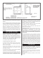
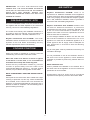
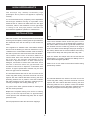
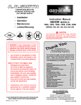
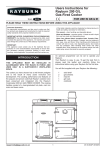
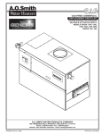
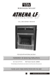
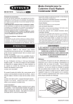
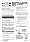
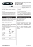
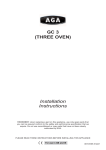
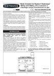
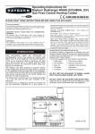
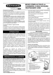
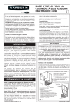
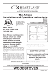
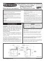
Better than you ever imagined
Installation Instructions for
Rayburn Cookmaster 200SFW
and Rayburn Cookmaster
Plus 212SFW Solid Fuel Cooker
Consumer Protection
where applicable, the pertinent parts that contain any of the listed
materials that could be interpreted as being injurious to health and
safety, see below for information.
As responsible manufacturers we take care to make sure that our
products are designed and constructed to meet the required safety
standard when properly installed and used.
Firebricks, Fuel beds, Artificial Fuels - when handling use
disposable gloves.
IMPORTANT NOTICE: PLEASE READ THE ACCOMPANYING
WARRANTY. Any alteration that is not approved by Aga could
invalidate the approval of the appliance, operation of the warranty
and could affect your statutory rights.
Fire Cement - when handling use disposable gloves.
Glues and Sealants - exercise caution - if these are still in liquid
form use face mask and disposable gloves.
All local regulations including those referring to National and
European standards need to be complied with when installing
the appliance.
Glass Yarn, Mineral Wool, Insulation Pads, Kerosene/Gas Oil may be harmful if inhaled, may be irritating to skin, eyes, nose and
throat. When handling avoid inhaling and contact with skin or
eyes. Use disposable gloves, face-masks and eye protection.
After handling wash hands and other exposed parts. When
disposing of the product, reduce dust with water spray, ensure that
parts are securely wrapped.
Important
This appliance may contain some of the materials that are
indicated. It is the Users/Installers responsibility to ensure that the
necessary personal protective clothing is worn when handling,
WARNING
THE ASHPIT DOOR AND FIREBOX DOORS MUST
BE LOCKED CLOSED AT ALL TIMES DURING
NORMAL USE, EXCEPT WHEN LIGHTING OR REFUELLING
PERFORMANCE
REMEMBER, when replacing a part on this
appliance, use only spare parts that you can be
assured conform to the safety and performance
specification that we require. Do not use
reconditioned or copy parts that have not been
authorised by AGA.
6 kW. This provides about 2 kW to hot water and 4 kW
to the appliance. Other fuels may give a slightly
different result.
Weight of Rayburn Cookmaster Plus 212SFW - 300 Kgs.
Weight of Rayburn Cookmaster 200SFW - 240 Kgs.
The Rayburn Cookmaster 200SFW is intended to be
used for cooking only. The Rayburn Cookmaster Plus
212SFW is intended to supply heating for cooking and
domestic hot water.
There is no requirement for an electrical power supply.
The mean flue gas temperature of the Rayburn
Cookmaster 200SFW directly downstream of the flue
spigot at nominal heat output is 131ºC.
The Rayburn Cookmaster 200SFW has been tested
using Taybrite manufactured smokeless fuel only. The
nominal heat output of this appliance is 4.4 kW.
The Rayburn Cookmaster Plus 212SFW has been
tested using Taybrite manufactured smokeless fuel and
wood logs. The nominal heat output of this appliance is
The mean flue gas temperature of the Rayburn
Cookmaster Plus 212SFW directly downstream of the
flue spigot at nominal heat output is 210ºC.
DESN 510179 D
[email protected]
1
08/06 EINS 514406
Minimum clearance to
combustible materials
150mm.
Fig. 1
and towel rail are lagged. When the hot water storage
cylinder is very closely coupled to the boiler, a towel rail
is advisable as a heat leak, and lagging should not be
applied. A radiator is not recommended.
The cooker fully meets the requirements of BS: 1252
and is fully approved by the HETAS Ltd Approval
Scheme.
Air for combustion within the firebox and the rate of
burning is determined by the manually operated
spinwheel control on the ashpit door and flue damper.
To obtain the boiler outputs the fire must be idled
overnight, and daytime cooking take place.
All installations must be fitted with a drain tap at the
lowest point of the system.
With normal usage in 24 hours continuous burning the
Rayburn Cookmaster Plus 212SFW has an
approximate output of 100 gallons of hot water. To
provide 2 or 3 hot baths at intervals and normal
household requirements, the following conditions must
be fulfiled:-
IMPORTANT NOTE: THESE INSTRUCTIONS MUST
BE STRICTLY OBSERVED. IF THEY ARE
DISREGARDED (E.G. AN UNLAGGED OR OVERSIZE CYLINDER), CONSUMPTION OF FUEL MAY BE
EXCESSIVE, AND THE COOKER DAMAGED BY
OVERFIRING.
HOT WATER SYSTEM
Rayburn Cookmaster Plus 212SFW - It is
recommended that a 140 litre (30 galls) indirect hot
water storage cylinder of the double feed type, (e.g.
manufactured by Albion Cylinders) complying with BS
1566 Part 1: DF Type 8 should be lagged and fixed
vertically as near as possible to the cooker.
In some circumstances it may be possible to overheat
the appliance and the water inside will boil. This will be
evident by the sound of a knocking noise coming from
the appliance and pipes around the house. If this occurs
close off all air controls and manually start the central
heating pump if fitted. Opening the oven doors and
hotplate covers will help to release heat from the
appliance. Be aware that steam and boiling water will
be expended from any open vent from the heating
system probably in the roof space at the expansion
tank.
The maximum water pressure is 1.75 bar.
The water capacity of the boiler is 7 litres.
The 28mm minimum diameter primary flow and return
pipes must not exceed 10m in length and pipes longer
than 5m must be lagged.
THE BOILER
Ensure that the flow pipe has an open vent and rises
continuously from the boiler to the cylinder to ensure
good gravity circulation.
Rayburn Cookmaster Plus 212SFW - Unscrew the
sheet metal cover plate on the side of the cooker and
remove the insulating material from behind it.
The water draw-off pipes to the taps must be dead-leg
connection from the vent/expansion pipe.
Joint the flow and return connections to the boiler,
replace the insulating material and screw on the cover
plate and collar.
A towel rail of not more than 0.5m2 heating surface may
be heated providing the flow and return pipes are not
more than 5m each in length, and provided the cylinder
The boiler is now ready for connection to the hot water
cylinder.
2
IMPORTANT: LIFT OUT THE HOTPLATE AND
CEMENT SEAL THE JOINT BETWEEN THE BOILER
FACE AND ITS LOCATING FACE ON THE FIREBOX
SIDES WITH FIRE CEMENT. RENEW ANY
BRICKWORK CEMENTED JOINTS THAT MAY HAVE
AIR SUPPLY
Rayburn Cookmaster 200SFW: There is no
requirement for additional ventilation as this appliance
is rated at less than 5kW. Should another appliance be
used in the property and the total heat output is greater
than 5 kW, additional ventilation must be provided in
accordance with the Building Regulations.
OPENED IN TRANSIT.
PREPARATION OF SITE
The non-combustible hearth must be solid and level
and together with the walls adjacent to the cooker and
chimney, conform to current Building Regulations.
Rayburn Cookmaster Plus 212SFW: Provision must
be made for additional ventilation. A permanent
unobstructed air vent having a minimum effective area
of 5.5 cm 2 must communicate to outside air or an
adjacent room which in turn has a permanent vent of at
least the same size to outside air.
If a flue draught stabiliser is fitted in the flue this vent
size must be increased to a minimum 23.5 cm2. If his
appliance us used with an additional appliance of a
similar type then the air supply must be adequate for
both appliances in accordance with the Building
Regulations.
The cooker and chimney flue installation should be in
accordance with the relevant recommendations of
BS8303, BS. 6461 Part 1 and BS. 7566 Parts 1 to 4.
Rayburn Cookmaster Plus 212SFW - The boiler
installation section must also be in accordance with the
byelaws of the local Water Undertaking and any
relevant requirements of the Local Authority.
COOKER POSITION
Any air inlet grilles must be positioned so that they are
not liable to blockage.
When the cooker is installed in a recess it must be
‘freestanding’ and not built-in solid at the sides.
It is not permissible to use an air extraction device in
the same room as the appliance, unless additional
ventilation is provided to prevent any adverse effect on
the flue.
Where the cooker is to stand in a recess or against
a wall which is to be tiled, in no circumstances
should the tiles overlap the cooker top plate.
Ensure that any combustible material e.g. kitchen
furniture is spaced away from the cooker to the
recommended distances. See Fig. 1. The work surface
however, may be fitted to the top plate on both sides.
Effect of Extractor Fan
Avoid if possible the installation of an extractor fan in
the same room as the appliance or the room where the
permanent air vent is located.
NOTE: SMOKE/SMELL EMITTED DURING INITIAL
USAGE
Some parts of the cooker have been coated with a light
covering of protective oil, this may cause smoke/smell
to be emitted, and is normal and not a fault with the
appliance, it is therefore advisable to open doors and or
windows to allow for ventilation. Lift the insulating lids to
prevent staining the linings.
Compensating extra air inlets must be introduced
equivalent to the capacity of the fan wheel when fitted.
3
THE CHIMNEY
The minimum chimney draught requirement for the
200SFW at nominal total heat output is 2.5 Pa.
The minimum chimney draught requirement for the
212SFW at nominal total heat output is 12 Pa.
The mean flue gas temperature of the Rayburn
200SFW directly downstream of the flue spigot at
nominal heat output is 131ºC.
The mean flue gas temperature of the Rayburn
212SFW directly downstream of the flue spigot at
nominal heat output is 210ºC.
The appliance is not suitable for installation in a shared
flue system
Checking Existing Chimney
The internal and external location of the chimney should
be checked before the appliance is installed and
rectification made where necessary to prevent leakage
or porosity. The soundness of the chimney which
should have a minimum flue dimension of 150mm can
be confirmed by smoke testing.
Fig. 2
DESN 510181 C
Fig. 3
DESN 510182 C
Fig. 4
DESN 510183 C
Advice on the test method can be obtained from
HETAS Ltd.
When repairing or re-using existing chimneys it is
recommended that the building control officer be
consulted before the commencement of work with
particular attention to the chimney height and its
termination
The chimney MUST be swept before installation.
Erecting New Chimney
The flue through the chimney should be formed with
pre-cast moisture and acid resistant liners with a
minimum internal diameter of 150mm diameter and all
in accordance with the current Building Regulations
(England and Wales) and in Scotland the Building
Standards (Scotland) (Consolidation) Regulations and
the Codes of Practice for chimneys and flues BS. 6461
Part 1 and BS. 7566 Parts 1 to 4.
Ensure the chimney liners are free of projecting internal
building jointing composition before the appliance is
installed.
Factory-Made Insulated Chimneys
It is recommended the chimney be ceramic lined and
comply with BS. 4543: Part 2.
The minimum diameter for a straight chimney is 150mm
and there should be not more than two bends of 45º
from vertical.
4
In Fig. 3 the cooker is connected direct to a brick flue.
Horizontal pipe runs between cooker and brick flue
must not be used.
IN ALL TYPE OF CHIMNEYS THE MINIMUM HEIGHT
FOR CORRECT OPERATION OF THE CHIMNEY IS
4.5m AND SHOULD TERMINATE ABOVE THE ROOF
IN ACCORDANCE WITH REGIONAL STATUTORY
REQUIREMENTS RECOMMENDED FLUE DRAUGHT
- 12 pa MINIMUM. THE APPLIANCE SHOULD BE
INSTALLED AND CONFORM TO THE CURRENT
CODES OF PRACTICE FOR INSTALLATION OF
DOMESTIC HEATING AND COOKING APPLIANCES
BURNING SOLID FUEL - BS 8303.
ALWAYS ADVISE THE USER TO CLEAN THE
COOKER FLUES IN ACCORDANCE WITH THE
OPERATING INSTRUCTIONS AND TO HAVE THE
CHIMNEY SWEPT AT A MINIMUM OF 12 MONTHLY
INTERVALS
AFTER
THE
COOKER
IS
COMMISSIONED.
In Fig. 4 the cooker is connected to an existing brick
flue with a length of flue pipe. Square bends and
horizontal runs must not be used. There must be a
cleaning door at every bend.
NOTE: WHATEVER METHOD OF INSTALLATION IS
EMPLOYED. AIR MUST NOT BE ALLOWED TO
ENTER THE CHIMNEY EXCEPT THROUGH THE
COOKER. ALL JOINTS MUST BE AIR-TIGHT.
If the chimney is unlined, and there is any doubt about
its condition, it should be lined in accordance with
Current Building Regulations.
COOKER FLUE CONNECTION
PROVISION MUST ALWAYS BE MADE FOR
SWEEPING THE CHIMNEY
The position of available types of flue layouts are shown
in Figs. 2, 3 and 4, the cooker flue chamber is
adaptable to providing either top or back flue outlets, by
means of the reversible loose socket.
a) Rear Flue Outlet
This must only be used where there is a brick flue
immediately behind the cooker. Provision must be
made for a condensate collecting vessel and
cleaning door. See Fig. 3.
IMPORTANT: CEMENT TYPE PIPES AND FITTINGS
MUST NOT BE USED WITHIN 2m OF COOKER.
CHIMNEYS OF PLAIN PIPE ARE NOT
RECOMMENDED BUT CERTAIN PROPRIETARY
MAKES OF INSULATED CHIMNEY ARE SUITABLE.
EXTENDED HORIZONTAL FLUE PIPE CONNECTION
IS ALLOWED UP TO A MAXIMUM OF 150mm IN
LENGTH.
NO BEND CONNECTIONS ARE ALLOWED.
b) Top Flue Outlet
The cooker should be connected to the main flue via
a 125mm minimum diameter cast iron flue pipe or
appropriately internally/externally vitreous enamelled
mild steel pipe and be sealed to the cooker flue
chamber with soft rope and fire cement. Any bends
in the flue pipe must not be less than 135º (45º from
vertical) and be complete with a cleaning door.
FLUE LAYOUTS
In Fig. 2 the cooker is installed in an existing recess.
There must be a clearance of not less than 150mm
between the top of the flue pipe and any overhanging
brickwork.
Any cavities or pockets above the register plate should
as far as possible be filled and if necessary the flue pipe
should be extended into the throat of the chimney and a
soot door provided for chimney sweeping.
If a flue liner or insulated chimney is used, the size
should not be less than 150mm.
5
HIGH UPDRAUGHTS
Tall chimneys may develop excessively high
updraughts which prevent the appliance operating
correctly.
It is recommended that a proprietary brand adjustable
flue draught stabiliser having an openable cross
sectional area of 126cm2 be fitted above the flue pipe
connection, either in the brickwork or into a right angle
‘T’ fitting in the flue pipe position that will not
inconvenience appliance operation or maintenance.
INSTALLATION
Fig. 5
Place the cooker in the intended position and lift out the
surface ground hotplate, checking that the joint between
the underside of the hob and the top of the cooker are
intact.
DESN 513152
Fit the flue chamber which should be given a 1mm
smear of fire cement on the underside then screwed to
the cooker. Make sure there is a good seal between the
flue chamber and the cooker top (if there is an ingress
of air it can affect the flue draught and proper working of
the cooker). Before the fire cement hardens remove any
surplus with a damp cloth then polish with a dry cloth.
If the appliance is installed near combustible material
then as well as adhering to minimum clearances in Fig.
1 additional non-combustible insulation must be fitted to
the wall to protect the area around the flue and fluebox.
The insulation must reach a minimum distance of
150mm either side of the flue/flue box and follow the
line of the flue. The minimum specification for this
material is Superwool 607 LTI with a density of
320kg/m3, a thickness of 10mm and a self finish. There
must be a minimum 16mm air gap between the
insulation board and an adjacent combustible wall
surface. A higher specification material may be used
but the air gap must be maintained.
Open the firebox and ashpit doors and check that the
bottomgrate is in position. Operate the riddling lever to
ensure the bottomgrate operation.
Failure to do so can result in the enamel surface being
permanently marked.
The handrail brackets are held on the front ends of the
cooker top-plate casting. Remove the travel nuts and
replace with the handrail brackets ensuring the fibre
protecting washers are in position. Insert the handrails
with fitted endcaps into the brackets, positioning them
correctly, and tighten the locating bolts (Fig. 8).
The handrail brackets are held on the front end of the
cooker top-plate casting. Remove the travel nuts and
replace with the handrail brackets ensuring the fibre
protecting washers are in position. Insert the handrail
with fitted endcaps into the brackets, positioning them
correctly and tighten the locating bolts. (See Fig. 5).
Any joints which have opened should be made good
with fire cement provided.
Replace the hotplate making sure that it is seating
evenly on the soft rope and that it is approximately
1.5mm proud of the enamelled top plate, with an equal
space all round.
Connect pipework to boiler flow and return tappings.
6
TESTING AND COMMISSIONING
After completing the installation, the Heating Contractor
should demonstrate to the user, the operation of the
appliance and the routine flue operating method.
1.
Check that the system is full of water and free
from air pockets. (Rayburn Cookmaster Plus
212SFW only).
2.
Select and install the appropriate burning grate
as required by the customer (see Users
Instructions for method).
3.
When lighting pull the flue chamber damper open
to maximum.
4.
Add paper and sticks with a small quantity of fuel
through the fuelling aperture onto bottomgrate
and close the firebox door.
5.
Open ashpit door, ignite fuel and close ashpit door
when fuel is well alight with spinwheel on ashpit
door at required setting.
(6.
Allow the cooker to heat up gradually at first time
lighting.
NOTE: The water capacity of the boiler is 7 litres.
FIREBRICK REPLACEMENT
The firebricks fitted to Rayburn Cookers are of first
quality manufacture, and providing the cooker has been
installed and used correctly will have a reasonable life.
They are, however, expendable items and in time will
require renewal.
The renewal of firebricks is not a major operation and
can be carried out by the average person.
Replacement bricks either in sets or singly can be
obtained from your Rayburn distributor.
LEAVE INSTRUCTIONS FOR FUTURE USE
7
For further advice or information contact your
local distributor/stockist
With Aga’s policy of continuous product
improvement, the Company reserves the right to
change specifications and make modifications to
the appliance described at any time.
Manufactured by
Aga
Station Road
Ketley Telford
Shropshire TF1 5AQ
England
www.aga-web.co.uk
www.agacookshop.co.uk
www.agalinks.com
8