1
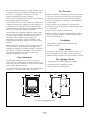
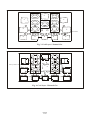
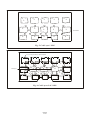
CHARNWOOD
GROSVENOR
Operating
and
Installation Instructions
Bishops Way, Newport, Isle Of Wight, PO3O 5WS, U.K.
Tel: (01983) 537799 Fax: (01983) 5377887
Charnwood Grosvenor
Safety Information
Important Information
It is most important that both you, the customer and the installation engineer not only follow the instructions in this
booklet, but that you are satisfied that the following conditions have been complied with.
This stove must not be used with any solid fuel, it is only suitable for natural gas or liquefied petroleum gas (LPG)
according to the burner unit supplied.
Ensure that the local gas distribution conditions, the nature of the gas pressure and the adjustment of the stove are
compatible.
Check that the burner data plate corresponds with the type of gas which is to be used i.e. natural gas or LPG.
The burner unit data plate is attached by a chain to the underside of the burner unit.
The site of the stove i.e. the chimney, the flue and hearth etc., must comply with current Building regulations and Codes of
Practice before the stove is installed.
The chimney flue outlet must be correctly positioned to align with the flue outlet on the stove that you have bought.
Connection to the chimney, the job of the installation engineer, is detailed in Section 1.
The stove must not be used with the door open.
Safety Reminders
Charnwood stoves are efficient appliances giving off convected, conducted and radiated heat. All the surfaces of the stove
(except the controls,) are working surfaces and become hot in use. They must not be touched or have any combustible
objects or material placed on or near them. Adequate precautions should always be taken to protect children, the elderly, the
infirm and pets, etc. from coming into contact with the stove.
Technical Data
Burner
Natural Gas (G20)
Natural Gas (G25)
LPG (G30)
Burner
Nat. Gas (G20)
Nat. Gas (G25)
LPG (G30)
Gas Flow
Rate
(m3/h)
0.42
0.488
0.103
Input
(kW)
4.5
4.5
3.7
Pilot Model
Injector
Injector Pressure
P4 48 Co Pilot NG20/A/400/M9/BE BRAY 82/280
14 mbar
P4 48 Co Pilot NG20/A/400/M9/BE BRAY 82/280
21.5 mbar
P4 49 Co Pilot LP37/A/400/M9/BE BRAY 92/140
16 mbar
Page 2
SV 2/00
Charnwood Grosvenor
Operating Instructions
Please go through this section with the installation
engineer so that you fully understand all the basic
operating and maintenance procedures for your stove.
a. Switching On/ Ignition.
Depress the control knob and turn counter clockwise. Gas
will flow to the pilot burner, the piezo igniter will give off
a high voltage spark & the pilot burner will light. (More
than one attempt may have to be made on first lighting the
fire.) Keep the control knob depressed for approximately
10 seconds to heat up the thermocouple, Turn the control
knob fully counter clockwise to release gas to the main
burner.
The engineer will be happy to answer your questions and
give you any help you may need.
General Notes
This stove is not for use with any solid fuels. It is only
suitable for Natural (mains) Gas or LPG (Liquified
Petroleum Gas) when the correct burner is fitted.
Please remember that when the stove is alight it is very
hot.
b. Control of Gas Flow.
Turning the control knob clockwise reduces the gas rate
from the maximum to the pre-set minimum setting.
Turning between maximum & minimum does not actuate
the piezo igniter. The control valve can only be set on pilot
by depressing the knob & turning it to the pre selected
pilot position.
EXCEPT FOR THE CONTROLS NEVER TOUCH
THE STOVE WITH YOUR BARE HANDS WHILST
IT IS HOT.
The stove must not be touched when it is in operation.
However, if you do need to do so after it has been turned
off and before it has completely cooled down (usually after
about one hour) please make sure that you wear stout oven
gloves.
Flue Spillage Safety Monitoring Device
A Safety Cut-Off System.
All stoves are fitted with an Oxygen Depletion Sensitive
Pilot so that should the flue and/or chimney become
blocked at any time, the stove will automatically cut off.
Normally the pilot can be re-ignited after waiting about
five minutes for the sensor to cool down, but in the event
of the system tripping, have the flue and chimney checked
by your installation engineer.
Lighting and controlling the stove.
Control Knob
Remember that the stove is designed to be operated with
the door and spinwheel securely closed.
Fig. 1. Gas Controls
1. Near the stove will be the gas isolation tap. Turn this to
the on position.
c. Switching Off When in Pilot Position.
Press control knob and turn clockwise to off.
2. Between the front and rear legs on the right hand side of
the stove you will find the burner control knob, as shown
in Fig. 1.
IMPORTANT
Interruption of Gas Supply.
Page 3
SV 2/00
Should the stove burner cut out for any reason you
should not try to re-light it for at least 5 minutes. If you
are then unable to re-light the pilot as described earlier
you should contact your stove supplier or engineer.
To The Customer
During normal operation, for example in the winter
months when the stove will be in regular use, we advise
that the pilot is left running continuously as this will allow
for quick and easy lighting, while at the same time helping
to prevent condensation. When the stove is not being used
for long periods, i.e. in the summer then we advise that the
gas supply is turned off at the isolation tap.
PLEASE NOTE: When the stove is first operated it
should be run at its maximum setting for several hours to
help the painted coating to cure. However, if you are able
to run the stove for a minimum of four hours then the full
curing process will be completed.
PLEASE READ THE FOLLOWING PROCEDURES AND
SERVICE CHECKS BUT PLEASE NOTE THEY MUST
ALL BE CARRIED OUT BY A QUALIFIED INSTALLATION ENGINEER. IF THE DOOR GLASS BECOMES
DAMAGED OR BROKEN-DO NOT USE THE STOVE.
Glass Replacement
1. Before carrying out the glass replacement we suggest
that, for safety reasons, the gas supply is turned off at the
isolation tap.
2. When the stove is cold remove door: See stove assembly
instructions.
3. Protect the working surface by laying the door on plenty
of newspaper or cardboard.
While the paint is curing there may be a little smoke given
off the surface of the stove accompanied by a slight smell
and traces of vapour. This is perfectly normal and quite
harmless. However, for your own comfort keep the room
well ventilated until the curing process is completed. The
slight smell may linger for the first week or so of
operation.
Customer Reminder
IT IS A LEGAL REQUIREMENT THAT THE
COMPLETE ASSEMBLY, INSTALLATION AND
COMMISSIONING OF GAS FIRED STOVES IS
CARRIED OUT BY A PROFESSIONALLY QUALIFIED
AND ACCREDITED GAS FITTER. YOU MUST NOT
ATTEMPT THIS YOURSELF.
MAINTENANCE & SERVICING
PROCEDURES.
Stove Cleaning
The stove surfaces are treated with an extremely durable
high temperature resistant paint cleaned by brushing down
with a clean shoe brush. If any of the black paint should
need retouching you can obtain the correct paint from your
stove supplier. Don't wash the stove or let water remain on
any surface when it is cold as this may cause rusting.
4. Remove all glass securing clips and all the broken glass.
5. Fit the new glass, ordered from your stove supplier,
ensuring that the sealing cord is correctly positioned
between the glass and the cast iron door frame. If this
sealing cord is damaged in any way a replacement can be
obtained from your stove supplier.
6. Re-secure the clips and nuts. Do not over-tighten as this
could crack the glass. We suggest hand tight, just enough
to ensure a good seal.
7. Re-fit the door making sure it is securely closed, before
re-establishing the pilot light as described above.
Fume Spillage Check
This test must be carried out by the installation engineer
when the stove is first commissioned and then we suggest
every 12 months to ensure that the products of combustion
are not spilling into the room. The test is carried out by
running the stove for ten minutes and then holding a
smoke match close to the diverter box to make sure the
smoke is drawn up the into the flue way. Do not use a
lighted match or a naked flame. The air flow must be
drawn to the chimney with sufficient draught. If the smoke
is disturbed then repeat the test a few minutes later. If the
smoke is still disturbed by escaping products of combustion
turn the stove off and contact your installation engineer
Regular Servicing For Safety And
Efficient Operation.
Glass Cleaning
Under normal use the glass should remain clean. However,
if the glass needs cleaning, this can easily be done with a
suitable glass cleaner available from your stove supplier.
Servicing should be carried out annually by a qualified
installation engineer when the stove is cold and the gas
supply turned off at the isolation tap. The following points
should checked:
1. Remove all the coals and clean any dust and debris from
Page 4
SV 2/00
the top of the burner unit. Ideally a vacuum cleaner should
be used, but if not a soft brush will do.
2. Check the condition of the coals. Any damaged ones
will affect the efficient operation of the stove and should be
replaced with new ones available from your stove supplier.
We hope these instructions have been clear and helpful and
you are now able to enjoy the full benefit of your stove. If
you have any queries or have found any part not as straight
forward as you would like, then please don't hesitate to call
us. Any suggestions for improvements are most welcome.
Please keep these instructions handy for future reference.
Most Important: Before installing the stove, check the
burner data plate, this must correspond with the type of gas
which is to be used, i.e. Natural Gas or LPG.
3. All gas joints should be checked to make sure they are
completely sealed and that the gas supply and pressure is
to specification.
4. The pilot jets are correctly set and clear of obstruction.
5. The chimney should also be checked to make sure there
are no restrictions or blockages.
6. Finally re-lay the coals and light the stove as described
earlier.
Problem Solving
Although we recommend that the customer is familiar with
the following it is important that the installation engineer
is contacted to rectify any difficulties.
The gas pilot will not stay alight:
1. Ensure there is a gas supply to the property and that the
isolation tap is in the "on" position.
2. Hold the control knob in the lighting position for at least
20 seconds once the burner is alight, to ensure adequate
heat operation of the safety thermocouple valve.
3. Make sure that the pilot injector is not obstructed or
blocked and that it is free from dust or dirt.
4. Finally ensure that the thermocouple, a very delicate
electro-mechanical device, has not become damaged in any
way. If it is damaged a replacement pilot assembly should
be obtained and fitted by your installation engineer.
FINAL REMINDERS
We remind you that it is a legal requirement that the stove
is installed by a qualified and accredited installation
engineer. Improper installation, adjustment, alteration,
service or maintenance can cause injury and/or damage to
property.
If you are in the slightest doubt about any aspect of your
stove's performance or you require additional information
then please contact your stove supplier or qualified
installation engineer.
At the risk of stating the obvious, please do not store, keep
or use petrol or any other flammable liquids, vapours or
substances anywhere near the stove or any other heating
appliance.
Page 5
SV 2/00
Charnwood Grosvenor
Installation Instructions
Notes to the Installation Engineer: Please make sure the
customer is familiar with the initial lighting and operating
procedures before leaving the site and that this instruction
booklet is left with them when the final commissioning is
complete.
And Fire Opening Specification.
The location of Charnwood Grosvenor model stoves
should have the following space around them:
The hearth should protrude at least 150mm (6”) in front of
the stove body and be at least 12mm (1/2”) thick.
Please check that the following components are included
before you start on the assembly.
In most buildings with solid concrete floors this
requirement will have been met by the floor itself. There
should also be a gap of at least 150mm (6”) on either side
of the stove, more if possible as the greater the space the
greater the amount of heat being released into the room. If
the stove is to be fitted into an existing opening there
should be a minimum of 150mm (6”) clearance on both
sides, with the back of the flue diverter box 15mm clear of
the rear wall.
The following stove components are delivered in 2 boxes:
Box 1: 1 Stove Body inc. baffle and flue diverter.
Box 2: 1 Burner Unit and coal set.
Assembly
IMPORTANT: ENSURE THAT THE CONCEALED
DOOR LOCK IS REMOVED BEFORE ATTEMPTING
TO OPEN THE GLASS DOOR USING THE HANDLE .
On all stove installations no combustible material should
cover the hearth, or be placed any closer then 225mm (9”)
from the stove. This includes carpeting and other
combustible floor coverings.
* Remove spinwheel from the bottom centre of door.
* Remove the lower bolt, using a 13mm spanner or socket,
and retain.
Connection To The Chimney.
Use 125mm dia. flue pipe to make the chimney connection.
If required, 100mm dia flue pipe may be used.
* Open door using handle and remove contents packed
inside stove, including front fire bar, noting location for
reassembly.
Before you install the stove make sure the chimney flue
outlet is correctly positioned to align with the flue outlet on
* Fit draught diverter to rear of stove using nuts and bolts
provided.
* Fit baffle plate by locating on the 4 lugs inside body with
the curved edge towards the front of body curving upwards
as shown in Fig. 2.
Baffle Plate
* Insert burner through door aperture with valve on right
hand side.
* Manoeuvre burner and locate so that rear lugs fit over
rear base plate: front lugs sitting on front of base plate and
secure with two bolts through top of base plate, the gas
valve will then be neatly located through cut out in right
hand side of stove body.
Flue Spillage Monitoring System.
Charnwood Grosvenor stoves are fitted with an oxygen
depletion sensitive pilot.
Location And Recommended Hearth
Fig. 2. Baffle Plate
Page 6
SV 2/00
the stove and that the chimney is in good condition. If not,
a chimney liner must be installed or a suitable class 2 gas
flue used. An up-draught is necessary to ensure the
products of combustion are fully evacuated.
The stove must be installed in accordance with current gas
and building regulations applicable.
Connect and seal the stove flue collar to the chimney with
a length of pipe fitting for a depth of at least 20mm (3/4").
A minimum of 610 mm (2ft) of vertical pipe should be
established before the flue direction is changed, unless the
stove is to be used with a fanned (powered) flue.
The flue must have a minimum height of 3 metres (10ft),
however to ensure optimum performance we recommend
3.6 metres (12ft) or higher. The flue must be free of
obstruction and any dampers must be fixed in a
permanently open position. Ensure the chimney is not
closed and that it has been swept prior to the stove being
installed.
Gas Pressure.
Make sure that there is adequate gas pressure and volume
to the stove. The relevant pressures are on the data plate.
Ensure that the gas pressure to the stove is maintained
when it is operating at the same time as other appliances
in the building.
The gas pressure can be obtained by unscrewing the
pressure test nipple and applying a suitable pressure gauge
i.e. a manometer.
Pressures to be as stated on the data plate.
Before any coals are placed in position make sure that the
burner is operating correctly. The flame should be fairly
even across the burner top.
Ventilation
Under normal circumstances no additional room
ventilation is needed.
Make sure that rain, birds or any foreign body cannot get
into the chimney to cause damage or a blockage. This
problem can normally be overcome by fitting an approved
Gas Cowl. It is essential to the effective running of your
stove that the chimney draws properly to allow the
products of combustion to escape.
Coals Layout
The approved layout of the coals is shown in Figs. 3, 4, 5
and 6. Adjustments may be made on this basis to give a
beautiful looking fire. Spare coals are provided in the pack.
Gas Connection.
The gas supply must be properly sized to provide the
correct gas rate at running pressure when measured at the
inlet valve. The final connection to the stove must be made
with a suitable 8mm dia gas pipe.
It is essential that a gas isolation tap is provided upstream
of the stove, in a position that is easily accessible.
Pre Lighting Checks
1. All building work and flue sealing is complete.
2. The front fire bar is refitted in position.
3. All the coals are correctly placed.
403
308
540
132
i/d
157
Off
t
Pilo
386
242
Grosvenor Overall Dimensions
(all dimensions are in mm)
Page 7
SV 2/00
513
Air Tunnel
Air Tunnel
2
1
4
L
3
L
Air Tunnel
L
5
L
L
ø8.0 Holes
6
7
S
8
S
9
S
10
S
S
Fig. 3. Coal Layer 1 Natural Gas
11
12
L
1st Layer below shown dotted
15
18
L
13
L
16
L
19
17
L
20
L
14
L
L
Fig. 4. Coal Layer 2 Natural Gas
Page 8
SV 2/00
L
L
21
L
11
12
L
6
7
L
13
L
8
L
14
L
9
L
15
L
L
10
L
L
ø8.0 Holes
1
2
S
3
S
4
S
5
S
Fig. 5. Coal Layer 1 LPG
1st Layer below, shown dotted
21
20
24
3rd Layer
L
23
L
26
25
S
16
22
L
L
S
17
S
18
L
L
Fig. 6. Coal Layers 2 & 3 LPG
Page 9
SV 2/00
L
19
L
S