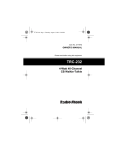
1
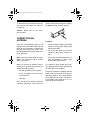
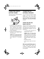
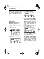
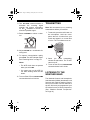
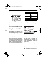
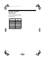
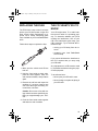
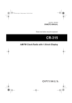
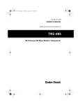
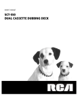
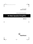
21-1709.fm Page 1 Monday, January 29, 2001 10:29 AM
Cat. No. 21-1709
OWNER’S MANUAL
Please read before using this equipment.
TRC-519
40-Channel Mobile CB Radio
with WX Alert and SAME
21-1709.fm Page 2 Monday, January 29, 2001 10:29 AM
FEATURES
Your RadioShack TRC-519 40-Channel
Mobile CB Radio provides two-way
communications on the citizen’s radio
band and also lets you tune to local and
national weather service broadcasts.
This CB is perfect for recreational, business, or emergency use. You can call
other people who have CBs at home, in
their vehicles, or at campsites, (for example). You can also connect optional
equipment to your CB, such as external
speakers, or a DC power supply and
base station antenna to set up a base
station in your home. The built-in 40channel PLL (phase-locked loop) frequency synthesizer uses a precise frequency reference crystal for reliable and
exact tuning.
RF Gain Control — prevents overloading due to strong RF signals.
Your CB has these features:
To use this CB, you need a mobile or
base station antenna. Your local RadioShack store has a wide variety of antennas. For more information, see
“Connecting an Antenna” on Page 6.
ACE (Audio Clarity Enhancer) — suppresses noise levels while leaving the
signal intact during reception. It enhances the transmission and provides a significant reduction in transmission and
reception noise.
WX Alert/SAME (Specific Area Message Encoding) — warns you of serious weather conditions using visual and
audio alarms tailored to the level of
weather severity.
Seven
Preprogrammed
Weather
Channels — let you manually select
from ten US weather frequencies to stay
informed about current weather conditions as you travel.
Maximum Allowable Legal Power
Output — gives you the greatest available range.
TX Indicator — lights to show when the
radio is transmitting.
Digital Channel Display — makes the
channel number easy to see.
External Speaker Jack — lets you connect your CB to an external speaker.
Screw-On MIC Connector — ensures
a secure microphone connection.
The Federal Communications Commission (FCC) does not require you to have
a license to operate this CB. However,
you must know Part 95 of FCC Rules. It
explains the proper operation of a Class
D citizen’s band CB. We enclosed a
copy of Part 95 with your CB radio.
We recommend you record your CB’s
serial number here. The number is on
the back of the CB.
Serial Number:
© 1999 Tandy Corporation.
All Rights Reserved.
RadioShack is a registered trademark used by Tandy Corporation.
2
21-1709.fm Page 3 Monday, January 29, 2001 10:29 AM
CONTENTS
Installation ...............................................................................................................
Before You Begin ...............................................................................................
Attaching the Microphone Holder .......................................................................
Mounting the CB .................................................................................................
Connecting the Microphone ...............................................................................
Connecting an Antenna ......................................................................................
Connecting Vehicle Battery Power .....................................................................
Connecting an External Speaker ........................................................................
Using the CB as a Base Station .........................................................................
4
4
4
4
5
6
7
7
7
Operation ................................................................................................................. 9
Receiving Transmissions and Setting Squelch .................................................. 9
Transmitting ...................................................................................................... 10
Listening to the Weather Band ......................................................................... 10
Using Weather Alert/SAME ........................................................................ 11
Common Uses for a CB ................................................................................... 12
Business Uses ........................................................................................... 12
Personal Uses ........................................................................................... 12
Transmission Courtesy ..................................................................................... 13
Maximum Range .............................................................................................. 13
Reducing Noise ................................................................................................ 13
Using Common 10-Codes .................................................................................... 15
Weather Channel Frequencies ......................................................................... 16
Troubleshooting .................................................................................................... 17
Care and Maintenance .......................................................................................... 18
Replacing the Fuse .......................................................................................... 19
The FCC Wants You to Know ........................................................................... 19
Specifications ....................................................................................................... 20
3
21-1709.fm Page 4 Monday, January 29, 2001 10:29 AM
INSTALLATION
BEFORE YOU BEGIN
Your CB’s display is protected during
shipment by a piece of clear film. Carefully peel off this film before using your
radio for the first time.
3. Attach the holder at the mounting
location using the supplied machine
screws and lock washers.
ATTACHING THE
MICROPHONE HOLDER
You can connect the microphone holder
to either side of the CB or to another location in your vehicle. To attach the
holder to either side of the CB, horizontally or vertically, secure it using the supplied machine screws and lock washers.
MOUNTING THE CB
The most common mounting location for
this CB is under a vehicle’s dashboard.
However, if you use the TRC-519 as a
base station, you can place it on a desk,
shelf, or table (see “Using the CB as a
Base Station” on Page 7).
If you are mounting the CB in a vehicle,
choose a location where:
• you can easily reach the CB.
To attach the holder to another location
in the vehicle, such as the dashboard,
follow these steps.
1. Using the holder as a template,
mark the positions for the mounting
screw holes at the desired location.
2. At each marked position, drill a hole
slightly smaller than the supplied
mounting screws.
Caution: Be careful not to drill into
anything behind the mounting surface.
4
• wires and cables are clear of the vehicle’s pedals or other moving parts.
• the CB is not directly in front of heating vents.
• all wires and cables can reach their
connection points.
Warning: If you use the CB in a vehicle,
mount it securely to avoid damage to the
CB or vehicle or injury to anyone in the
vehicle during sudden starts or stops.
21-1709.fm Page 5 Monday, January 29, 2001 10:29 AM
Follow these steps to mount the CB using the supplied hardware.
1. Using the mounting bracket as a
template, mark the positions for the
screw holes on the mounting surface.
2. In each marked position, drill a hole
slightly smaller than the supplied
mounting screws.
Caution: Be careful not to drill into
objects behind the mounting surface.
4. Attach the CB to the mounting
bracket using the supplied rubber
washers and mounting knobs.
CONNECTING THE
MICROPHONE
1. Align the slot on the bottom of the
microphone’s plug with the ridge
inside the microphone jack. Then
fully insert the plug into the jack.
3. Using a Phillips screwdriver, attach
the mounting bracket to the mounting surface with the supplied screws
and lock washers.
2. Turn the plug’s locking nut clockwise
to tighten it.
3. Slide the microphone onto the
microphone holder.
5
21-1709.fm Page 6 Monday, January 29, 2001 10:29 AM
To disconnect the microphone from the
CB, unscrew the locking nut then pull
out the plug.
cable to the CB and connect the cable to
the ANT. jack on the back of the CB.
Caution: Never pull on the microphone’s cable.
CONNECTING AN
ANTENNA
Cautions:
There are many different types of CB
antennas for mobile CBs. Each antenna
type has its own benefits, so choose the
one that best meets your needs. Your
local RadioShack store sells a wide variety of antennas.
• Avoid routing the cable next to sharp
edges or moving parts, which might
damage the cable.
Note: If you are using this CB as a base
station, see “Using the CB as a Base
Station” on Page 7.
• Do not run the cable through the engine compartment or other areas
that produce extreme heat.
When you choose an antenna, keep in
mind that for the best performance you
should mount the antenna:
For maximum range, adjust the antenna’s Standing Wave Ratio (SWR) using
an SWR meter (not supplied).
• as high as possible on the vehicle
• as far as possible from sources of
electrical noise
• vertically
Once you choose an antenna, follow its
mounting instructions. Then route the
6
• Do not run the cable next to power
cables or other radio antenna cables.
Follow the instructions supplied with the
SWR meter and antenna to adjust your
antenna’s SWR to the lowest possible
value. SWR values of 2.0:1 are generally acceptable, with readings of 1.5:1 or
lower being more desirable.
21-1709.fm Page 7 Monday, January 29, 2001 10:29 AM
CONNECTING VEHICLE
BATTERY POWER
CONNECTING AN
EXTERNAL SPEAKER
Follow these steps to connect the CB to
vehicle battery power.
You can connect an optional external
speaker to the CB. Use an 8-ohm
speaker with a 1/8-inch (3.5-mm) plug.
Insert the speaker’s plug into the CB’s
EXT. SP. jack. Your local RadioShack
store carries a wide selection of suitable
speakers.
To Chassis Ground (black)
To ACC Power (red)
1. Connect the red wire (with the inline fuse holder) on the back of the
CB to a terminal in your vehicle’s
fuse box that has power only when
the ignition is in the ACC (accessory) or ON position.
2. Connect the black ground wire to a
metal part of the vehicle’s frame
(chassis ground).
Caution: Do not connect the black
wire to a non-metallic (plastic) part,
or to any part insulated from the vehicle’s chassis by a non-metallic
part.
USING THE CB AS A
BASE STATION
Although this CB is designed mainly for
mobile use, you can also use it as a
base station with an AC power source.
For base station installation, you need
these items.
• a 12-volt DC power supply that can
supply at least 1.5 amps
Caution: Most 12-volt DC power
supplies plug into a standard AC
outlet to produce DC power. Before
connecting your CB to a 12-volt DC
power supply, read and follow the instructions included with the power
supply.
• base station antenna
• coaxial antenna cable and connectors
Note: Your local RadioShack store carries a wide selection of base station antennas, coaxial antenna cable, and
connectors. In addition, you can choose
from a selection of suitable base station
power supplies.
7
21-1709.fm Page 8 Monday, January 29, 2001 10:29 AM
Follow these steps to install the CB as a
base station.
Power
Supply
To –
Terminal
To + Terminal
1. Mount the base station antenna as
described in its owner’s manual.
Warning: Use extreme caution
when you install or remove a base
station CB antenna. If the antenna
starts to fall, let it go. It could contact
overhead power lines. If the antenna
touches a power line, contact with
the antenna, mast, cable, or guy
wires can cause electrocution and
death. Call the power company to
remove the antenna. DO NOT attempt to do so yourself.
2. Connect the antenna to the ANT.
jack on the back of the CB.
3. Connect the CB’s black power wire
to the negative (–) terminal on the
DC power supply.
4. Connect the CB’s red wire (with the
in-line fuse) to the positive (+) terminal on the DC power supply.
5. Connect the DC power supply to a
standard AC outlet.
8
21-1709.fm Page 9 Monday, January 29, 2001 10:29 AM
OPERATION
Before you use your CB, you should
know how to use it effectively and courteously. “Common Uses for a CB” on
Page 12 contains information that will
help you get more enjoyment from your
CB.
Caution: Do not attempt to use your CB
without first connecting it to an antenna.
RECEIVING
TRANSMISSIONS AND
SETTING SQUELCH
1. Rotate VOLUME fully counterclockwise
4. Turn RF GAIN fully clockwise.
5. Turn on the CB by turning OFF/VOLUME clockwise. The display lights
and the channel appears.
Note: The CB sounds an alert if it
detects a weather alert signal (see
“Using Weather Alert/SAME” on
Page 11).
6. Rotate VOLUME clockwise until you
hear a hissing sound.
2. Set CB/WX to CB.
7. Slowly turn SQUELCH clockwise
until the hissing sound stops.
3. Turn SQUELCH fully counterclockwise.
Note: To receive very weak signals,
turn SQUELCH counterclockwise.
You hear noise between transmissions, but you can also hear weak
transmissions (those not strong
enough to break through a higher
squelch setting). If the CB picks up
unwanted, weak transmissions, turn
SQUELCH clockwise to reduce the
CB’s sensitivity to these signals.
9
21-1709.fm Page 10 Monday, January 29, 2001 10:29 AM
8. Turn RF GAIN counterclockwise to
decrease the incoming signal
strength and prevent overloading.
Or, turn it clockwise to receive the
maximum possible signal .
9. Rotate CHANNEL to select a channel.
TRANSMITTING
Note: We recommend you try receiving
transmissions before you transmit.
1. To transmit, press the talk button on
the microphone. Hold the microphone about 2–3 inches from your
mouth and speak in a normal tone
of voice. The TX indicator turns on.
10. Adjust VOLUME to a comfortable listening level.
11. To improve communication quality,
press ACE. The ACE indicator lights.
See “Reducing Noise” on Page 13
Notes:
2. When you finish transmitting,
release the talk button. The TX indicator turns off.
• The ACE circuit does not operate
when you select WX.
3. To turn off the CB, turn OFF/VOLUME
counterclockwise until it clicks.
• You cannot turn on the ACE circuit while holding down the talk
button.
12. To turn off the CB, turn OFF/VOLUME
counterclockwise until it clicks.
10
LISTENING TO THE
WEATHER BAND
The National Oceanic and Atmospheric
Administration (NOAA) broadcasts local
forecast and regional weather information on one or more of seven channels in
the US. We have pre-programmed your
CB with all seven of these frequencies.
(See “Weather Channel Frequencies”
on Page 16.)
21-1709.fm Page 11 Monday, January 29, 2001 10:29 AM
To select a weather broadcast, set CB/
WX to WX, and turn CHANNEL to select
one of the frequencies.
Set CB/WX to CB to return to normal CB
operation.
Alert Type
You Hear
Warning
Continuous short beeps
Watch
Continuous three short
beeps
Statement
Continuous two short
beeps
Weather Alert
Continuous long beeps
Test and Other
Slow short beeps
To stop the alert tones, press ALERT
TONE OFF or the microphone’s talk button. SAME/ALT continues flashing until
you switch to WX.
Note: The microphone’s talk button
does not work when CB/WX is set to WX.
Using Weather Alert/SAME
When CB/WX is set to CB and the CB is
on, it automatically functions as a severe
weather warning radio by sounding an
alert when it detects a weather alert signal. This is especially useful when your
area is expecting severe weather conditions.
When your local weather station broadcasts a severe weather alert signal, the
CB sounds an alert tone and the radio’s
SAME ALT indicator lights according to
the emergency level encoded in the signal
To reduce the alert tone levels for subsequent alerts, hold down ALERT TONE
OFF for about 2-seconds. The tone
stops and the indicator flashes slowly. If
the radio receives a new SAME code
weather alert, three low-level, short
beeps sound while the indicator light
flashes slowly.
To return to the full alert mode, press the
microphone’s talk button or switch to
WX.
To listen to the weather information after
the radio receives an alert, set CB/WX to
WX. The SAME/ALT indicator turns off.
11
21-1709.fm Page 12 Monday, January 29, 2001 10:29 AM
Notes:
• Because of atmospheric conditions,
you might encounter times when the
signal your radio receives does not
contain information relevant to the
emergency level of the alert. This is
normal.
• The radio will sound an alert regardless of the channel setting.
• The CB will not sound an alert while
you are transmitting.
Caution: If you are in a rural or fringe
area, your radio might be triggered by
an alert broadcast in one area, but not
be triggered if you travel to another area
(even close by).
To verify actual reception, your radio
must receive a test or emergency alert
broadcast. In the US, the National
Weather Service (NWS) broadcasts a
test alert every week on Wednesday between 11 AM and 1 PM. To find out the
specific test schedule in your area, contact your local NOAA or National Weather Service office. These offices are
usually listed in the telephone directory
under “US Government, Department of
Commerce.”
COMMON USES FOR A CB
Like most activities, CB radio has its
customs and courtesies. The following
tips will help you get the most enjoyment
from your CB.
Business Uses
• Truck drivers and delivery personnel
can learn road and traffic conditions
and get assistance in locating destinations. A CB is also good company
on those “long hauls.”
• On construction crews, a CB quickly
pays for itself when you are calling
for additional materials or coordinating the activities of different work
crews.
• For security officers, a CB is more
than a convenience — it is a must
for both safety and efficiency.
Personal Uses
• Keep in touch with home while driving to work, to the store, or to a social activity. Let your family know you
are tied up in traffic or that you will
stop by the store on the way home.
• If you are a two-car (or more) family,
CBs are great for communicating
with family members while they are
in their cars.
• Contact friends or neighbors — find
out “what’s happening” or plan a
get-together.
12
21-1709.fm Page 13 Monday, January 29, 2001 10:29 AM
• Ever have car trouble or run out of
gas on the highway? What an assurance it is to be able to call for assistance!
• Camping, fishing, and other sports
are more fun with a CB. Locate a
buddy or find out “what’s cooking”
back at camp.
• the height of the antenna’s mounting
location — the higher the antenna,
the better the signal’s range
• the surrounding terrain — mountains and tall buildings limit the
range
• weather conditions
• the number of nearby CBs operating
on the same channel
TRANSMISSION
COURTESY
Please follow these guidelines of radio
courtesy when using your CB.
• Wait for a pause in someone else’s
transmission before you ask for a
break.
• If you do not receive an answer to
your call after a second attempt,
sign off and wait several minutes before trying again.
• Do not hold down the talk button
when you are not talking. (This is
called dead keying.)
• Assist callers with directions, information about road conditions, and
any other reasonable requests.
MAXIMUM RANGE
The maximum range and quality of CB
transmissions vary depending on the following conditions:
• the type and quality of antenna used
• standing wave ratio (SWR) between
the antenna and the CB.
Note: Your CB radio’s transmission
range is generally line-of-sight.
REDUCING NOISE
The Audio Clarity Enhance (ACE) circuit
uses compander (compressor and expander) technology to improve communication quality. The circuit maintains
the dynamic range while increasing the
signal-to-noise ratio as the gain is automatically controlled according to the input signal level. This results in a
reduction in wide band noise.
Because your CB is exceptionally quiet,
any noise you hear is probably from an
external source in your vehicle, such as
the alternator, another radio, or spark
plugs.
You can determine the noise’s source
by turning off the engine and operating
the CB with your vehicle’s ignition set to
ACC. If the noise is reduced, the problem is in your vehicle’s ignition or electrical system.
13
21-1709.fm Page 14 Monday, January 29, 2001 10:29 AM
Here are a few hints to help you reduce
or eliminate such noise:
• Make all CB power and antenna
wires as short as possible.
• Keep the power wires away from the
antenna wires.
• Be sure the chassis ground connection is secure.
• Replace old ignition wires with new,
high-voltage,
noise-suppression
wires.
• Install noise suppressors on your
spark plugs, or install new spark
plugs that have built-in noise suppressors.
• If problems persist, check your alternator/generator
and
regulator
gauges. You can reduce the noise
from these sources by using bypass
capacitors at the various output voltage points.
Your local RadioShack store has a wide
selection of noise-suppression accessories.
14
21-1709.fm Page 15 Monday, January 29, 2001 10:29 AM
USING COMMON 10-CODES
Citizen’s Band operators have largely
adopted the 10-codes for standard
questions and answers. These codes
permit faster communication and better
intelligibility in noisy areas. While not all
codes are listed, most of the more popular ones follow:
Code
Code
Meaning
10-26
Disregard last information.
10-27
I am moving to
channel____.
10-28
Identify your station.
10-32
I will give you a radio
check.
Meaning
10-1
Receiving poorly.
10-33
Emergency traffic.
10-2
Receiving well.
10-36
Correct time is____.
10-3
Stop transmitting.
10-37
10-4
OK, message
received.
Wrecker needed
at____.
10-38
Ambulance needed
at______
10-41
Please turn to
channel_____.
10-42
Traffic accident
at_____.
10-43
Traffic tie-up at____.
10-50
Break channel.
10-62
Unable to copy; use
telephone.
10-70
Fire at_____.
10-5
Relay message.
10-6
Busy, please stand
by.
10-7
Out of service.
10-8
In service
10-9
Repeat message.
10-10
Transmission completed, standing by.
10-11
Talking to rapidly.
10-12
Visitors present.
10-13
Advise Weather/Road
conditions.
10-17
Urgent business.
10-18
Anything for us?
10-19
Nothing for you.
Return to base.
10-20
My location is____.
10-21
Call by telephone.
10-22
Report in person
to____.
10-23
Please stand by.
10-25
Can you contact____.
Note: Although this table lists the 10codes’ meanings in the form of a statement, they can also be phrased as
questions (10-6: Are you busy?, 10-20:
What is your location?).
15
21-1709.fm Page 16 Monday, January 29, 2001 10:29 AM
WEATHER CHANNEL
FREQUENCIES
Your CB is programmed with the following United States weather service channel FM frequencies:
16
Channel
Frequency
(MHz)
WX1
162.400
WX2
162.425
WX3
162.450
WX4
162.475
WX5
162.500
WX6
162.525
WX7
162.550
21-1709.fm Page 17 Monday, January 29, 2001 10:29 AM
TROUBLESHOOTING
We do not expect you to have any problems with your CB, but if you do, the following
suggestions might help.
Symptom
Trouble receiving.
Suggestion
Make sure POWER is on.
Make sure SQUELCH is adjusted properly.
Be sure RF GAIN is fully clockwise.
Make sure the CB is set to an operating channel.
Make sure the microphone is securely connected.
Press ACE to improve communication quality.
Check for a good antenna connection.
Trouble transmitting.
Make sure the antenna cable is securely connected to the
antenna connector.
Make sure the antenna is fully extended.
Make sure all connections are secure and free of corrosion.
Make sure CB/WX is set to CB.
The CB is completely
inoperable.
Check the DC power cord and in-line fuse.
Replace the fuse. See “Replacing the Fuse” on Page 19.
If these tips do not solve the problem, do not attempt repairs or adjustments yourself.
The CB should be serviced only by a qualified radio technician. If you still have problems, take your CB to your local RadioShack store for assistance.
17
21-1709.fm Page 18 Monday, January 29, 2001 10:29 AM
CARE AND MAINTENANCE
Your RadioShack TRC-519 40-Channel Mobile CB Radio is an example of superior
design and craftsmanship. The following suggestions will help you care for your CB
so you can enjoy it for years.
Keep the CB dry. If it gets wet, wipe it dry immediately. Liquids might contain minerals that can corrode the electronic circuits.
Use and store the CB only in normal temperature environments. Temperature extremes can shorten the life of electronic devices and distort or
melt plastic parts.
Keep the CB away from dust and dirt, which can cause premature wear
of parts.
Handle the CB gently and carefully. Dropping it can damage circuit
boards and cases and can cause the CB to work improperly.
Wipe the CB with a damp cloth occasionally to keep it looking new. Do
not use harsh chemicals, cleaning solvents, or strong detergents to clean
the CB.
Modifying or tampering with the CB’s internal components can cause a malfunction
and might invalidate its warranty and void your FCC authorization to operate it. If
your CB is not performing as it should, take it to your local RadioShack store for assistance.
18
21-1709.fm Page 19 Monday, January 29, 2001 10:29 AM
REPLACING THE FUSE
The TRC-519’s 2-amp in-line fuse helps
protect your CB from power surges and
short circuits. When replacement is required, use a 2-amp, fast-acting glass
fuse, available at your local RadioShack
store.
Follow these steps to replace the fuse.
THE FCC WANTS YOU TO
KNOW
Your CB might cause TV or radio interference even when it is operating properly. To determine whether your CB is
causing the interference, turn off your
CB. If the interference goes away, your
CB is causing it. Try to eliminate the interference by:
• moving your CB away from the receiver
• contacting your local RadioShack
store for help
If you cannot eliminate the interference,
the FCC requires that you stop using
your CB radio.
1. Make sure the vehicle and CB are
both off.
2. Hold the fuse holder at both ends,
push the ends together, twist one
end counterclockwise, and pull them
apart.
3. Remove the old fuse and inspect its
condition. If it is blown, insert a new
one of the same type and rating. If it
is not blown, reinsert it.
Any adjustments to a CB must be made
by a qualified technician using the proper test equipment.
To be safe and sure:
• Never open your CB radio’s case.
• Never change or replace anything in
your CB radio.
Caution: Do not use a fuse with ratings other than those specified here.
Doing so might damage your TRC519.
4. Push the fuse holder ends together
and twist one end clockwise.
19
21-1709.fm Page 20 Monday, January 29, 2001 10:29 AM
SPECIFICATIONS
RECEIVER
Frequency Response (1 kHz, 0 dB Reference)
Lower, at 450 Hz ..................................................................................................... –3 dB
Upper, at 2500 Hz ................................................................................................... –3 dB
Intermediate Frequency
First IF .......................................................................................................... 10.695 MHz
Second IF........................................................................................................... 455 MHz
Maximum Sensitivity ..................................................................................................... 0.5 µV
Sensitivity for 10 dB S/N ................................................................................ 0.5 µV or Better
AGC Figure of Merit 50 mV for 10 dB Change in Audio Output .................................... 90 dB
Overload AGC Characteristics (from 50 mV to 1000 mV) ............................................... 4 dB
Overall Audio Fidelity at 6 dB Down ............................................................ 450 Hz–2500 Hz
Adjacent Channel Selectivity ......................................................................................... 55 dB
Image Rejection ........................................................................... Typically Better than 60 dB
IF Rejection .................................................................................................... 65 dB or Better
Maximum Audio Output Power .................................................................. 4 Watts at 8 ohms
Squelch Range ..................................................................... Adjustable from 0.5 µV to 1 mV
Receive Battery Drain ............................................................................ 280 mA to 1500 mA
(from No Signal to Maximum Output)
TRANSMITTER
Frequency Tolerance .............................................................................................. ±0.0005%
Maximum Output Power .......................................... 4 Watts (Maximum Allowed by the FCC)
Spurious Emission ....................................................................................... –65 dB or Better
Transmit Battery Drain .......................................................................... 1270 mA to 1870 mA
(from No Modulation to 80% Modulation Limit)
Modulation Frequency Response (1 kHz, 0 dB Reference):
Lower, at 450 Hz ..................................................................................................... –3 dB
Upper, at 2.5 kHz .................................................................................................... –3 dB
Modulation Type and Capacity ............................................................................ A3 and 85%
Microphone Sensitivity .................................................................... 3 µV for 50% Modulation
GENERAL
Channels ............................................................................................................................ 40
Frequency Range ....................................................................... 26.965 MHz to 27.405 MHz
Frequency Control ............................................................... Phase-Locked Loop Synthesizer
Operating Temperature Range ....................................................................... –22°F to 122°F
Power Requirements ..................................... 13.8V DC (12–16 Volts DC, Negative Ground)
Input Power ...................................................................................... 7.5 W (Reference Value)
Antenna .................................................................................... 50 Ohm (Coaxial Connector)
Microphone ....................................................................................................... Dynamic Type
Internal Speaker .......................................................................................... 16 Ohm, 5 Watts
Dimensions (HWD) ......................................................................... 19/16 × 59/16 × 75/16 Inches
(40 mm × 142 mm × 185 mm)
Weight ............................................................................................................................ 2 lbs
(930 g)
Specifications are typical; individual units might vary. Specifications are subject to change and
improvement without notice.
20
21-1709.fm Page 21 Monday, January 29, 2001 10:29 AM
NOTES
21
21-1709.fm Page 22 Monday, January 29, 2001 10:29 AM
22
21-1709.fm Page 23 Monday, January 29, 2001 10:29 AM
23
21-1709.fm Page 24 Monday, January 29, 2001 10:29 AM
Limited Ninety-Day Warranty
This product is warranted by RadioShack against manufacturing defects in material and workmanship under normal use for ninety (90) days from the date of purchase from RadioShack companyowned stores and authorized RadioShack franchisees and dealers. EXCEPT AS PROVIDED
HEREIN, RadioShack MAKES NO EXPRESS WARRANTIES AND ANY IMPLIED WARRANTIES,
INCLUDING THOSE OF MERCHANTABILITY AND FITNESS FOR A PARTICULAR PURPOSE,
ARE LIMITED IN DURATION TO THE DURATION OF THE WRITTEN LIMITED WARRANTIES
CONTAINED HEREIN. EXCEPT AS PROVIDED HEREIN, RadioShack SHALL HAVE NO LIABILITY OR RESPONSIBILITY TO CUSTOMER OR ANY OTHER PERSON OR ENTITY WITH RESPECT TO ANY LIABILITY, LOSS OR DAMAGE CAUSED DIRECTLY OR INDIRECTLY BY USE
OR PERFORMANCE OF THE PRODUCT OR ARISING OUT OF ANY BREACH OF THIS WARRANTY, INCLUDING, BUT NOT LIMITED TO, ANY DAMAGES RESULTING FROM INCONVENIENCE, LOSS OF TIME, DATA, PROPERTY, REVENUE, OR PROFIT OR ANY INDIRECT,
SPECIAL, INCIDENTAL, OR CONSEQUENTIAL DAMAGES, EVEN IF RadioShack HAS BEEN ADVISED OF THE POSSIBILITY OF SUCH DAMAGES.
Some states do not allow the limitations on how long an implied warranty lasts or the exclusion of incidental or consequential damages, so the above limitations or exclusions may not apply to you.
In the event of a product defect during the warranty period, take the product and the RadioShack
sales receipt as proof of purchase date to any RadioShack store. RadioShack will, at its option, unless otherwise provided by law: (a) correct the defect by product repair without charge for parts and
labor; (b) replace the product with one of the same or similar design; or (c) refund the purchase
price. All replaced parts and products, and products on which a refund is made, become the property of RadioShack. New or reconditioned parts and products may be used in the performance of
warranty service. Repaired or replaced parts and products are warranted for the remainder of the
original warranty period. You will be charged for repair or replacement of the product made after the
expiration of the warranty period.
This warranty does not cover: (a) damage or failure caused by or attributable to acts of God, abuse,
accident, misuse, improper or abnormal usage, failure to follow instructions, improper installation or
maintenance, alteration, lightning or other incidence of excess voltage or current; (b) any repairs
other than those provided by a RadioShack Authorized Service Facility; (c) consumables such as
fuses or batteries; (d) cosmetic damage; (e) transportation, shipping or insurance costs; or (f) costs
of product removal, installation, set-up service adjustment or reinstallation.
This warranty gives you specific legal rights, and you may also have other rights which vary from
state to state.
RadioShack Customer Relations, 200 Taylor Street, 6th Floor, Fort Worth, TX 76102
We Service What We Sell
04/99
RadioShack
A Division of Tandy Corporation
Fort Worth, Texas 76102
UTZZ01362ZZ
08A99
Printed in the Philippines