1
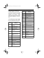
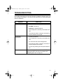
21-1701.fm Page 1 Thursday, August 5, 1999 12:50 PM
Cat. No. 21-1701
OWNER’S MANUAL
Please read before using this equipment.
TRC-501
40-Channel 2-Way CB Radio
21-1701.fm Page 2 Thursday, August 5, 1999 12:50 PM
INTRODUCTION
Your RadioShack TRC-501 40Channel 2-Way CB Radio is a high
performance CB with the maximum
legally allowable power and innovative styling.
Automatic Noise Limiting (ANL)
Circuit — reduces noise caused by
nearby electrical equipment such as
motors or automotive ignition systems.
This CB is perfect for recreational,
business, or emergency use. You
can call other people who have CBs
at home, in their vehicles, or at camp
sites. You can also connect optional
equipment to your CB, such as an
external PA speaker, or a DC power
supply and base station antenna to
set up a base station in your home.
DOWN/UP Channel Selector —
provides maximum convenience
when selecting channels.
LED Display — lets you easily see
the selected channel number.
Your CB has these features:
Universal Mounting Bracket —
lets you mount your CB securely in
your vehicle or on a table or shelf in
your home.
PLL (Phase-Locked Loop) Frequency Synthesizer — provides reliable and exact tuning using a
precise frequency reference crystal.
Note: To use this CB, you need a
mobile or base station antenna. Your
local Radio Shack store has a wide
variety of antennas.
Two Ceramic Filters — provide superior selectivity and prevent adjacent-channel interference.
Hysteresis Squelch Circuit —
compensates for fading signals and
eliminates signal chopping during reception.
We recommend you record your
CB’s serial number here. The number is on the CB’s back panel.
Serial Number_________________
© 1996 Tandy Corporation.
All Rights Reserved.
RadioShack is a trademark used by Tandy Corporation.
2
21-1701.fm Page 3 Thursday, August 5, 1999 12:50 PM
FCC INFORMATION
The Federal Communications Commission (FCC) does not require you
to have a license to operate this CB.
However, the FCC does require you
to read and know Part 95 of FCC
Rules. These rules apply to the operation of a Class D CB. We have provided a copy of these regulations
with your CB.
Warning: Do not open your CB to
make any internal adjustments. Internal adjustments must be made only
by authorized service personnel.
Internal adjustments and/or modifications can lead to illegal operation
as defined by Part 95 of FCC Rules.
Such illegal operation can lead to
very serious consequences.
Your CB might cause TV or radio interference even when it is operating
properly. To determine whether your
CB is causing the interference, turn
off your CB. If the interference goes
away, your CB is causing the interference. Try to eliminate the interference by:
• Moving your CB away from the
receiver.
• Contacting your local
dioShack store for help.
Ra-
If you cannot eliminate the interference, the FCC requires that you stop
using your CB.
To be safe and sure:
• Never open your CB’s case.
• Never modify your CB.
3
21-1701.fm Page 4 Thursday, August 5, 1999 12:50 PM
CONTENTS
Installation ........................................................................................................5
Mounting the Microphone Holder ................................................................5
Connecting the Microphone ........................................................................5
Mounting the TRC-501 ................................................................................ 5
Connecting an Antenna ...............................................................................6
Selecting an Antenna ........................................................................... 6
Connecting the Antenna .......................................................................7
Connecting an Optional External Speaker ..................................................7
Connecting Power ....................................................................................... 8
Using Vehicle Battery Power ................................................................8
Using the CB as a Base Station ...........................................................8
Operation .......................................................................................................... 9
Receiving Transmissions and Adjusting Squelch .......................................9
Transmitting ..............................................................................................10
CB Operation Tips .....................................................................................10
Common Uses for a CB Radio ...........................................................10
CB Courtesy ....................................................................................... 11
Maximum Range ................................................................................ 11
Using Common 10-Codes ..................................................................12
Troubleshooting ............................................................................................13
Reducing Noise .........................................................................................14
Maintenance ...................................................................................................15
Replacing the Fuse ...................................................................................16
Specifications ................................................................................................17
4
21-1701.fm Page 5 Thursday, August 5, 1999 12:50 PM
INSTALLATION
MOUNTING THE
MICROPHONE HOLDER
Using a Phillips screwdriver and the
supplied small screws and small
metal washers, attach the supplied
microphone holder horizontally or
vertically to either side of the CB.
(il-
Caution: Never pull on the
microphone cable.
MOUNTING THE
TRC-501
The most common mounting location
for this CB is under a vehicle’s dashboard. However, if you use the TRC501 as a base station, you can place
it on a desk, shelf, or table (see “Using the CB as a Base Station” on
Page 8).
If you are mounting the CB in a vehicle, choose a location where:
• You can easily reach the CB.
CONNECTING THE
MICROPHONE
• Wires and cables will not interfere with the vehicle’s pedals or
other moving parts.
Make sure the pins on the microphone cable’s plug are aligned with
the holes in the CB’s microphone
jack on the front of transceiver and
insert the plug into the jack.
• The CB is not directly in front of
heating vents.
To disconnect the microphone cable,
press and hold down the small tab on
the microphone plug, then pull out
the plug.
• All wires and cables will reach
their connection points.
Caution: If you use the TRC-501 in a
vehicle, mount it securely to avoid
damage to the CB or vehicle during
sudden starts or stops.
(il-
5
21-1701.fm Page 6 Thursday, August 5, 1999 12:50 PM
Follow these steps to mount the CB
using the supplied hardware.
1. Using the mounting bracket as a
template, mark the positions for
the three screw holes.
4. Attach the CB to the mounting
bracket using the rubber washers and mounting knobs.
(il(il-
2. In each marked location, drill a
hole slightly smaller than the
supplied large screws.
Caution: Be careful not to drill
into anything behind the mounting surface.
3. Using a Phillips screwdriver,
attach the mounting bracket to
the mounting surface with the
large screws and supplied lock
washers.
(il-
CONNECTING AN
ANTENNA
Caution: To prevent damage to your
CB, you must connect an antenna to
the CB before you operate it.
Selecting an Antenna
Although this CB is designed for mobile use, you can also use it as a
base station. When deciding on a
mobile or base-station antenna and
its location, consider these points:
• For the best performance, the
antenna should be vertical and
located as high as possible.
• The antenna and antenna cable
should be as far as possible
from sources of electrical noise
(ignition systems, gauges, etc.).
6
21-1701.fm Page 7 Thursday, August 5, 1999 12:50 PM
Your local RadioShack store sells a
variety of CB antennas (for both mobile and base-station use), coaxial
antenna cable, and connectors.
Connecting the Antenna
Once you choose an antenna, follow
the mounting instructions supplied
with it.
Warning: Use extreme caution when
you install or remove a base station
CB antenna. If the antenna starts to
fall, let it go! It could contact overhead power lines. If the antenna
touches the power line, contact with
the antenna, mast, cable, or guy
wires can cause electrocution and
death. Call the power company to remove the antenna. DO NOT attempt
to do so yourself.
Then route the antenna cable to the
CB and connect the cable to the ANTENNA jack on the back of the CB.
• Do not run the cable next to
power cables or other CB
antenna cables.
• Do not run the cable through a
vehicle’s engine compartment or
other areas that produce
extreme heat.
CONNECTING AN
OPTIONAL EXTERNAL
SPEAKER
To make the CB easier to hear in
noisy environments, you can connect
it to an external CB speaker. Use an
8-ohm speaker capable of handling
3–5 watts of power (such as RadioShack Cat. No. 21-549). The
speaker’s cable must have a 1/8-inch
plug.
Simply plug the speaker cable into
the CB’s EXT 8 Ω jack.
(il(il-
Speaker Cable
Cautions:
Note: When you connect an external
speaker, the CB’s internal speaker
automatically disconnects.
• Do not run the cable over sharp
edges or moving parts.
7
21-1701.fm Page 8 Thursday, August 5, 1999 12:50 PM
CONNECTING POWER
You can power this CB from your vehicle’s battery or from standard AC
power with an optional DC power
supply (such as Cat. No. 22-120).
Using Vehicle Battery Power
Using the CB as a
Base Station
Caution: Most 12-volt DC power
supplies plug into a standard AC outlet to produce DC power. Before connecting your CB to a 12-volt DC
power supply, read and follow the instructions provided with the power
supply.
(il(il-
1. Connect the CB’s red wire, with
in-line fuse, to a source of voltage that turns on and off with the
ignition switch, such as a spare
accessory terminal in your vehicle’s fuse box.
2. Connect the CB’s orange wire,
with in-line fuse, to a source of
voltage that supplies constant
positive (+) power, or directly to
your vehicle’s positive (+) battery terminal. This connection is
for memory back-up.
3. Connect the CB’s black wire to
your vehicle battery’s negative
(–) terminal, or a metal part of
the vehicle’s frame that is not
insulated from the frame by a
plastic part
8
1. Connect the CB’s red and
orange wires, each with in-line
fuses, to the DC power supply’s
positive (+) terminal.
2. Connect the CB’s black wire to
the DC power supply’s negative
(–) terminal.
3. Plug the power supply’s cord
into a standard AC outlet.
21-1701.fm Page 9 Thursday, August 5, 1999 12:50 PM
OPERATION
Before you start using your CB, you
should know how to use it effectively
and courteously. “CB Operation
Tips” on Page 10 has information
that will help you use and enjoy your
CB.
RECEIVING
TRANSMISSIONS AND
ADJUSTING SQUELCH
Caution: Do not attempt to use your
CB without first connecting an antenna to it.
1. Turn SQUELCH fully counterclockwise.
Note: If the CB picks up
unwanted, partial, or very weak
transmissions, turn SQUELCH
clockwise to decrease the CB’s
sensitivity to these signals. If
you want to listen to a weak or
distant station, turn SQUELCH
counterclockwise.
4. Adjust VOLUME to a comfortable
listening level.
5. Press DOWN to select lower
channel numbers or UP to select
higher channel numbers. The
channel number appears on the
display.
(il-
(il-
2. To turn on the CB, turn VOLUME
clockwise until you hear it click
and you hear a hissing sound.
The CB displays a channel number.
(il-
9
is
Important! Channel
reserved for motorist assistance
and for reporting emergency
information about accidents,
hazardous road conditions, and
so on. Always give emergency
messages priority on Channel 9.
6. To turn off the TRC-501, turn
VOLUME counterclockwise until
you hear it click.
3. Turn SQUELCH clockwise until
the hissing sound stops.
9
21-1701.fm Page 10 Thursday, August 5, 1999 12:50 PM
TRANSMITTING
CB OPERATION TIPS
We recommend you try receiving
transmissions before you transmit.
Like most activities, CB radio has its
customs and courtesies. The following tips will help you get the most enjoyment from your CB.
1. Follow Steps 1–5 under “Receiving Transmissions and Adjusting
Squelch.”
2. Hold the microphone 2 or 3
inches from your mouth. Then
press and hold down the microphone talk button and speak into
the microphone in a normal
voice. The TX indicator turns on.
(il-
Note: Do not speak too loudly
when transmitting. It does not
make your signal any stronger,
and might distort your transmission.
3. When you finish transmitting,
release the microphone talk button. The TX indicator turns off.
You can now receive transmissions.
4. To turn off the TRC-501, turn
VOLUME counterclockwise until
you hear it click.
10
Common Uses for a CB
Radio
Business Uses
• Truck drivers and delivery personnel can learn road and traffic
conditions and get assistance in
locating destinations. A CB is
also good company on those
“long hauls.”
• On construction crews, a CB
quickly pays for itself when you
are calling for additional materials or coordinating the activities
of different work crews.
• For security officers, a CB is
more than a convenience — it is
a must for both safety and efficiency.
Personal Uses
• Keep in touch with home while
driving to work, to the store, or to
a social activity. Let your family
know you are tied up in traffic or
that you will stop by the store on
the way home.
• If you are a two-car (or more)
family, CBs are great for communicating with family members
while they are in their cars.
21-1701.fm Page 11 Thursday, August 5, 1999 12:50 PM
• Contact friends or neighbors —
find out “what’s happening” or
plan a get-together.
• Ever have car trouble or run out
of gas on the highway? What an
assurance it is to be able to
radio
for
assistance!
• Camping, fishing, and other
sports are more fun with a CB.
Locate a buddy or find out
“what’s cooking” back at camp.
CB Courtesy
• Wait for a pause in someone
else’s transmission before you
ask for a break.
• If you do not receive an answer
to your call after a second
attempt, sign off and wait several minutes before trying again.
• Do not hold down the microphone talk button when you are
not talking. (This is called dead
keying.)
• Assist callers with directions,
information about road conditions, and any other reasonable
requests.
Maximum Range
The maximum range and quality of
CB transmissions vary depending on
these conditions:
• The type and quality of antenna
used.
• The height of the antenna’s
mounting location — the higher
the antenna, the better the signal’s range.
• The surrounding terrain —
mountains and tall buildings limit
the range.
• Weather conditions.
• The number of nearby CBs
operating on the same channel.
• Standing wave ratio (SWR)
between the antenna and the
CB. You can check the SWR
between the CB and a mobile or
base-station antenna using an
SWR tester (Cat. No. 21-523).
Follow the instructions supplied
with the SWR tester and the
mobile or base-station antenna
to change the SWR, if necessary.
11
21-1701.fm Page 12 Thursday, August 5, 1999 12:50 PM
Using Common 10-Codes
Citizen’s band operators have largely
adopted the 10-codes for standard
questions and answers. These
codes permit faster communication
and better intelligibility in noisy areas.
Code
Meaning
10-14
Information.
10-15
Message delivered.
10-16
Reply to message.
10-17
En route.
10-18
Urgent.
10-19
Contact ____________.
10-20
What is your location?
10-21
Call ___________ by telephone.
Cannot understand your
message.
10-22
Cancel last message.
10-2
Your signal is good.
10-23
Arrived at the scene.
10-3
Stop transmitting.
10-24
Assignment complete.
10-4
Message received and
understood.
10-26
Estimated time of arrival is
____________________.
10-5
Relay information to
________________.
10-30
Use caution.
10-31
Pick up.
10-6
I am busy or are you
busy?
10-33
Emergency traffic. Clear
the channel.
10-7
Out of service.
10-34
What time is it?
10-8
In service.
10-9
Repeat last message.
10-10
Negative (No).
10-11
____________ in service.
10-12
Stand by.
10-13
Report ____________
conditions.
These tables list the codes adopted
by the Associated Public Safety
Communications Officers (APCO).
Code
10-1
12
Meaning
21-1701.fm Page 13 Thursday, August 5, 1999 12:50 PM
TROUBLESHOOTING
If your CB is not working as it should, follow the suggestions below to see if you
can eliminate the problem. If you cannot, take the CB to your local RadioShack
store for assistance.
Symptom:
Trouble with reception
Check That:
• The CB is turned on.
• VOLUME is turned up.
• SQUELCH is adjusted properly.
• The microphone is securely connected to the
CB.
• The antenna cable is securely connected to
both the antenna and the CB.
Trouble with
transmission
• The CB is turned on.
• The microphone is securely connected to the
CB.
• All connectors are clean and tightened.
• The antenna cable is securely connected to
both the antenna and the CB.
• You are fully pressing the microphone talk button.
CB does not work at all
The power supply (either vehicle or 12V DC) is
working and the in-line fuse is not blown; see
“Replacing the Fuse” on Page 16.
13
21-1701.fm Page 14 Thursday, August 5, 1999 12:50 PM
REDUCING NOISE
Here are a few hints to help you reduce or eliminate such noise:
The Automatic Noise Limiting (ANL)
circuit helps keep background noise
to a minimum. However, strong
sources of electrical noise (such as
your vehicle’s ignition, another radio,
or spark plugs) might be more than
the circuit can compensate for.
• Replace old ignition wires with
new, high-voltage, noise-suppression wires.
If you operate the TRC-501 with a vehicle’s engine off, you should not
have any problems with noise. If you
use the CB with the engine on, you
can determine the source of the
noise by turning off the engine and
operating the CB with the ignition set
to ACC. If most or all of the noise
goes away, the problem is in your vehicle’s ignition or electrical system.
• Be sure that the ground connection (black wire) is secure.
• Install noise suppressors on
your spark plugs, or install new
spark plugs that have built-in
suppressors.
If problems persist, check your alternator/generator, regulator, and gauges. Noise from these sources can be
reduced or eliminated using bypass
capacitors at various output voltage
points.
Your local RadioShack store has a
wide selection of noise-suppression
accessories.
14
21-1701.fm Page 15 Thursday, August 5, 1999 12:50 PM
MAINTENANCE
Your TRC-501 40-Channel 2-Way CB Radio is an example of superior design
and craftsmanship. The following suggestions will help you care for your CB so
you can enjoy it for years.
Keep the CB dry. If it gets wet, wipe it dry immediately. Liquids
might contain minerals that can corrode the electronic circuits.
Handle the CB gently and carefully. Dropping it can damage circuit boards and cases and can cause the CB to work improperly.
Keep the CB away from dust and dirt, which can cause premature
wear of parts.
CLEANER
Wipe the CB with a damp cloth occasionally to keep it looking
new. Do not use harsh chemicals, cleaning solvents, or strong detergents to clean the CB.
Modifying or tampering with the CB’s internal components can cause a malfunction and might invalidate your CB’s warranty and void your FCC authorization to
operate it. If your CB is not performing as it should, take it to your local RadioShack store for assistance.
15
21-1701.fm Page 16 Thursday, August 5, 1999 12:50 PM
REPLACING THE FUSE
The TRC-501’s 2-amp and 1-amp
fuses help protect your CB from power surges and short circuits.
• If the black wire’s fuse is blown,
replace it with a 2-amp, fast-acting glass fuse (Cat. No. 2701007).
• If the orange wire’s fuse is
blown, replace it with a 1-amp,
fast-acting glass fuse (Cat. No.
270-1005).
Follow these steps to check and replace each fuse, if necessary.
(il-
1. Make sure the power source
and CB are both turned off.
2. To open the fuse holder, push
the fuse holder ends together,
then turn either end counterclockwise and release it.
3. If the fuse is blown, replace it.
Caution: Make sure you replace
the fuse only with another fuse
of the same type and rating.
4. To close the fuse holder, push
the fuse holder ends together,
then turn either end clockwise.
16
21-1701.fm Page 17 Thursday, August 5, 1999 12:50 PM
SPECIFICATIONS
RECEIVER
Frequency Coverage............................................ All 40 CB Channels (Class D)
26.965 to 27.405 MHz
Sensitivity ..................................................... 0.7 µV or better for 10 dB (S+N)/N
Adjacent Channel Rejection ........................................................................55 dB
Audio Output ......................................................................... 3 Watts (Minimum)
Frequency Response ...................................................
–6 dB (at 450–2500 Hz)
Intermediate Frequency .............................................................1st 10.695 MHz
2nd 455 kHz
Cross Modulation .......................................................................................50 dB
Squelch ............................................................ Adjustable from 0.5 µV to 1 mV
TRANSMITTER
Frequency Coverage............................................. All 40 CB Channels (Class D)
26.965 to 27.405 MHz
Output Power ............................................................... 4 Watts (FCC Maximum)
Type of Modulation ...................... AM Double Sideband, Full Carrier Modulation
Modulation Capability ................................................................................... 90%
Spurious Emission.....................................................................................–60 dB
Frequency Tolerance...............................................................................±200 Hz
Antenna Impedance ............................................................................... 50 Ohm
Current Drain (13.8 volt supply) ................................ 1 Amp with No Modulation
1.6 Amps with 90% Maximum Modulation
GENERAL
Power Requirements ........................................13.8 Volts DC, Negative Ground
Dimensions........................................................ 15/16 x 41/2 x 65/16 Inches (HWD)
(33 x 114 x 160 mm)
Weight ..................................................................................................... 15.7 oz
(445 g)
Specifications are typical; individual units might vary. Specifications are subject
to change and improvement without notice.
17
21-1701.fm Page 18 Thursday, August 5, 1999 12:50 PM
NOTES
18
21-1701.fm Page 19 Thursday, August 5, 1999 12:50 PM
19
21-1701.fm Page 20 Thursday, August 5, 1999 12:50 PM
RadioShack Limited Warranty
This product is warranted against defects for 90 days from date of purchase from
RadioShack company-owned stores and authorized RadioShack franchisees and dealers. Within this period, we will repair it without charge for parts and labor. Simply bring
your RadioShack sales slip as proof of purchase date to any RadioShack store. Warranty does not cover transportation costs. Nor does it cover a product subjected to misuse or accidental damage.
EXCEPT AS PROVIDED HEREIN, RadioShack MAKES NO EXPRESS WARRANTIES
AND ANY IMPLIED WARRANTIES ARE LIMITED IN DURATION TO THE DURATION
OF THE WRITTEN LIMITED WARRANTIES CONTAINED HEREIN. Some states do
not permit limitation or exclusion of implied warranties; therefore, the aforesaid limitation(s) or exclusion(s) may not apply to the purchaser.
This warranty gives you specific legal rights and you may also have other rights which vary from
state to state.
We Service What We Sell
10/95
RadioShack
A Division of Tandy Corporation
Fort Worth, Texas 76102
7A6
Printed in Thailand