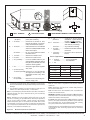
1
R
Owner’s Manual
Installation and Operation
Model:
QV36DC-A
CAUTION
DO NOT DISCARD THIS MANUAL
•
Important operating and
maintenance instructions included.
• Read,
understand and follow
these instructions for safe
installation and operation.
• Leave this manual with
party responsible for use
and operation.
D
DI O N
SC OT
AR
D
WARNING
WARNING: If the information in these
instructions is not followed exactly, a fire
or explosion may result causing property
damage, personal injury, or death.
• Do not store or use gasoline or other flammable vapors and liquids in the vicinity of
this or any other appliance.
• What to do if you smell gas
- Do not try to light any appliance
- Do not touch any electrical switch. Do not
use any phone in your building.
- Immediately call your gas supplier from a
neighbor’s phone. Follow the gas supplier’s instructions.
- If you cannot reach your gas supplier, call
the fire department.
• Installation and service must be performed
by a qualified installer, service agency, or the
gas supplier.
This appliance may be installed as an OEM installation in
manufactured home (USA only) or mobile home and must be
installed in accordance with the manufacturer’s instructions
and the manufactured home construction and safety standard,
Title 24 CFR, Part 3280 or Standard for Installation in Mobile
Homes, CAN/CSA Z240MH.
This appliance is only for use with the type(s) of gas indicated
on the rating plate.
HOT SURFACES!
Glass and other surfaces are hot during
operation AND cool down.
Hot glass will cause burns.
• DO NOT touch glass until it is cooled
• NEVER allow children to touch glass
• Keep children away
• CAREFULLY SUPERVISE children in same room as
fireplace.
• Alert children and adults to hazards of high temperatures.
High temperatures may ignite clothing or other flammable
materials.
• Keep clothing, furniture, draperies and other flammable
materials away.
This appliance has been supplied with an integral barrier
to prevent direct contact with the fixed glass panel. DO
NOT operate the appliance with the barrier removed.
Contact your dealer or Hearth & Home Technologies if the
barrier is not present or help is needed to properly install one.
In the Commonwealth of Massachusetts installation must be
performed by a licensed plumber or gas fitter.
See Table of Contents for location of additional Commonwealth
of Massachusetts requirements.
Installation and service of this appliance should be
performed by qualified personnel. Hearth & Home
Technologies suggests NFI certified or factory-trained
professionals, or technicians supervised by an NFI
certified professional.
Quadra-Fire • QV36DC-A • 2161-900 Rev. C • 6/09
1
SAFETY AND WARNING INFORMATION
!
READ and UNDERSTAND all instructions carefully
before starting the installation. FAILURE TO
FOLLOW these installation instructions may result in
a possible fire hazard and will void the warranty.
!
These units MUST use one of the vent systems
described in the Installing the Fireplace section of
the Owner’s Manual. NO OTHER vent systems or
components MAY BE USED.
!
Prior to the first firing of the fireplace, READ the
Using Your Fireplace section of the Owners Guide.
!
This gas fireplace and vent assembly MUST be
vented directly to the outside and MUST NEVER be
attached to a chimney serving a separate solid fuel
burning appliance. Each gas appliance MUST USE
a separate vent system. Common vent systems are
PROHIBITED.
!
INSPECT the external vent cap on a regular basis
to make sure that no debris is interfering with the air
flow.
!
The glass door assembly MUST be in place and
sealed, and the trim door assembly MUST be in
place on the fireplace before the unit can be placed
into safe operation.
!
!
!
!
!
!
!
2
DO NOT USE this appliance if any part has been
under water. Immediately CALL a qualified service
technician to inspect the unit and to replace any part
of the control system and any gas control which has
been under water.
THIS UNIT IS NOT FOR USE WITH SOLID FUEL.
Installation and repair should be PERFORMED by a
qualified service person. The appliance and venting
system should be INSPECTED before initial use and
at least annually by a professional service person.
More frequent cleaning may be required due to
excessive lint from carpeting, bedding material, etc. It
is IMPERATIVE that the unit’s control compartment,
burners, and circulating air passageways BE KEPT
CLEAN to provide for adequate combustion and
ventilation air.
Always KEEP the appliance clear and free from
combustible materials, gasoline, and other flammable
vapors and liquids.
NEVER OBSTRUCT the flow of combustion and
ventilation air. Keep the front of the appliance CLEAR
of all obstacles and materials for servicing and proper
operations.
Due to the high temperature, the appliance should
be LOCATED out of traffic areas and away from
furniture and draperies. Clothing or flammable
material SHOULD NOT BE PLACED on or near the
appliance.
Children and adults should be ALERTED to
the hazards of high surface temperature and
should STAY AWAY to avoid burns or clothing
ignition. Young children should be CAREFULLY
SUPERVISED when they are in the same room as
the appliance.
!
DO NOT OPERATE this appliance with the glass
door removed, cracked, or broken. Replacement of
the glass door should be performed by a licensed or
qualified service person. DO NOT strike or slam the
glass door.
!
The glass door assembly SHALL ONLY be replaced
as a complete unit, as supplied by the gas fireplace
manufacturer. NO SUBSTITUTE material may be
used.
!
DO NOT USE abrasive cleaners on the glass door
assembly. DO NOT ATTEMPT to clean the glass
door when it is hot.
!
!
!
Turn off the gas before servicing this appliance. It
is recommended that a qualified service technician
perform an appliance check-up at the beginning of
each heating season.
Any safety screen or guard removed for servicing
must be replaced before operating this appliance.
DO NOT place furniture or any other combustible
household objects within 36 inches of the fireplace
front.
Quadra-Fire • QV36DC-A • 2161-900 Rev. C • 6/09
TABLE OF CONTENTS
Safety and Warning Information .................................................2
Service Parts Lists .......................................................................4
Section 1: Approvals and Codes ................................................7
Appliance Certification ....................................................................7
Installation Codes ...........................................................................7
High Altitude Installations ...............................................................7
Electrical Codes..............................................................................7
Requirements for the Commonwealth of Massachusetts ...............8
Section 2: Getting Started ...........................................................9
Introducing the Quadra-Fire Gas Fireplaces ..................................9
Pre-installation Preparation ............................................................9
Section 3: Installing the Fireplace ............................................11
Constructing the Fireplace Chase ................................................11
Step 1 Locating the Fireplace ...................................................11
Step 2 Framing the Fireplace ...................................................12
Step 3 Installing the Vent System .............................................14
A. Vent System Approvals ............................................14
B. Installing Vent Components .....................................21
C. Vent Termination ......................................................24
Step 4 Positioning, Leveling, and
Securing the Fireplace ..................................................27
Step 5 The Gas Control System ...............................................27
Step 6 The Gas Supply Line ....................................................28
Step 7 Gas Pressure Requirements .........................................28
Step 8 Wiring the Fireplace ......................................................29
Step 9 Finishing ........................................................................30
Step 10 Installing Trim, Logs, and Ember Material .....................31
Installing the Trim ..........................................................31
Refractory Kit Placement ..............................................31
Positioning the Logs ......................................................32
Shutter Settings ............................................................32
Placing the Ember Material ...........................................32
Glass Specifications ......................................................32
Step 11 Before Lighting the Fireplace ........................................32
Step 12 Lighting the Appliance ...................................................33
Step 13 Climate Control .............................................................34
After the Installation .....................................................................34
Section 4: Maintaining and Servicing Your Fireplace. ...........34
Section 5: Troubleshooting. .....................................................35
Î Limited Lifetime Warranty. ........................................................37
Î Contact Information .....................................................................39
Î = Contains updated information.
Quadra-Fire • QV36DC-A • 2161-900 Rev. C • 6/09
3
1
Approvals and
Codes
Appliance Certification
High Altitude Installations
The fireplace model discussed in this Owner’s Manual
has been tested to certification standards and listed by the
applicable laboratories.
U.L. Listed gas appliances are tested and approved without
requiring changes for elevations from 0 to 2,000 feet in the
U. S. A. and in Canada.
Certification
MODELS: QV36DC-A
LABORATORY: Underwriters Laboratories, Inc. (UL)
TYPE: Vented Gas Fireplace Heaters
STANDARD: ANSI Z21.88a-2007 • CSA 2.33a-2007
Installation Codes
The fireplace installation must conform to local codes.
Before installing the fireplace, consult the local building
code agency to ensure that you are in compliance with all
applicable codes, including permits and inspections.
In the absence of local codes, the fireplace installation must
conform to the National Fuel Gas Code ANSI Z223.1 (in the
United States) or the CAN/CGA-B149 Installation Codes
(in Canada). The appliance must be electrically grounded
in accordance with local codes or, in the absence of local
codes with the National Electric Code ANSI/NFPA No.
70 (in the United States), or to the CSA C22.1 Canadian
Electric Code (in Canada).
This model may be installed in a bedroom or bed-sitting
room in the U.S.A. and Canada.
When installing this appliance at an elevation above 2,000
feet, it may be necessary to decrease the input rating by
changing the existing burner orifice to a smaller size. Input
rate should be reduced by 4% for each 1000 feet above
a 2000 foot elevation in the U.S.A. or 10% for elevations
between 2000 and 4500 feet in Canada. If the heating
value of the gas has been reduced, these rules do not
apply. To identify the proper orifice size, check with the
local gas utility.
If installing this appliance at an elevation above 4,500 feet
(in Canada), check with local authorities.
Electrical Codes
NOTICE: This appliance must be electrically wired and
grounded in accordance with local codes or, in the absence
of local codes, with National Electric Code ANSI/NFPA
70-latest edition or the Canadian Electric Code CSA
C22.1.
• A 110-120 VAC circuit for this product must be protected
with ground-fault circuit-interrupter protection, in compliance
with the applicable electrical codes, when it is installed in
locations such as in bathrooms or near sinks.
Quadra-Fire • QV36DC-A • 2161-900 Rev. C • 6/09
7
Note: The following requirements reference various
Massachusetts and national codes not contained in this
document.
Requirements for the Commonwealth of
Massachusetts
For all side wall horizontally vented gas fueled equipment
installed in every dwelling, building or structure used in
whole or in part for residential purposes, including those
owned or operated by the Commonwealth and where the
side wall exhaust vent termination is less than seven (7)
feet above finished grade in the area of the venting, including but not limited to decks and porches, the following
requirements shall be satisfied:
Installation of Carbon Monoxide Detectors
At the time of installation of the side wall horizontal vented
gas fueled equipment, the installing plumber or gas fitter
shall observe that a hard wired carbon monoxide detector
with an alarm and battery back-up is installed on the floor
level where the gas equipment is to be installed. In addition, the installing plumber or gas fitter shall observe that
a battery operated or hard wired carbon monoxide detector with an alarm is installed on each additional level of
the dwelling, building or structure served by the side wall
horizontal vented gas fueled equipment. It shall be the
responsibility of the property owner to secure the services
of qualified licensed professionals for the installation of
hard wired carbon monoxide detectors.
In the event that the side wall horizontally vented gas fueled equipment is installed in a crawl space or an attic,
the hard wired carbon monoxide detector with alarm and
battery back-up may be installed on the next adjacent
floor level.
In the event that the requirements of this subdivision can
not be met at the time of completion of installation, the
owner shall have a period of thirty (30) days to comply
with the above requirements; provided, however, that during said thirty (30) day period, a battery operated carbon
monoxide detector with an alarm shall be installed.
Approved Carbon Monoxide Detectors
Each carbon monoxide detector as required in accordance with the above provisions shall comply with NFPA
720 and be ANSI/UL 2034 listed and IAS certified.
Signage
A metal or plastic identification plate shall be permanently mounted to the exterior of the building at a minimum
height of eight (8) feet above grade directly in line with the
exhaust vent terminal for the horizontally vented gas fueled heating appliance or equipment. The sign shall read,
in print size no less than one-half (1/2) in. in size, “GAS
VENT DIRECTLY BELOW. KEEP CLEAR OF ALL OBSTRUCTIONS”.
Inspection
The state or local gas inspector of the side wall horizontally vented gas fueled equipment shall not approve the
installation unless, upon inspection, the inspector observes carbon monoxide detectors and signage installed
in accordance with the provisions of 248 CMR 5.08(2)(a)1
through 4.
Exemptions
The following equipment is exempt from 248 CMR
5.08(2)(a)1 through 4:
• The equipment listed in Chapter 10 entitled “Equipment
Not Required To Be Vented” in the most current edition
of NFPA 54 as adopted by the Board; and
• Product Approved side wall horizontally vented gas fueled equipment installed in a room or structure separate
from the dwelling, building or structure used in whole or
in part for residential purposes.
MANUFACTURER REQUIREMENTS
Gas Equipment Venting System Provided
When the manufacturer of Product Approved side wall
horizontally vented gas equipment provides a venting
system design or venting system components with the
equipment, the instructions provided by the manufacturer
for installation of the equipment and the venting system
shall include:
• Detailed instructions for the installation of the venting
system design or the venting system components; and
• A complete parts list for the venting system design or
venting system.
Gas Equipment Venting System NOT Provided
When the manufacturer of a Product Approved side wall
horizontally vented gas fueled equipment does not provide the parts for venting the flue gases, but identifies
“special venting systems”, the following requirements
shall be satisfied by the manufacturer:
• The referenced “special venting system” instructions
shall be included with the appliance or equipment installation instructions; and
• The “special venting systems” shall be Product Approved by the Board, and the instructions for that system shall include a parts list and detailed installation
instructions.
A copy of all installation instructions for all Product Approved side wall horizontally vented gas fueled equipment, all venting instructions, all parts lists for venting
instructions, and/or all venting design instructions shall
remain with the appliance or equipment at the completion
of the installation.
See Gas Connection section for additional Commonwealth of Massachusetts requirements.
8
Quadra-Fire • QV36DC-A • 2161-900 Rev. C • 6/09
2
Getting Started
Introducing Quadra-Fire Gas Fireplaces
Quadra-Fire direct vent gas fireplaces are designed to operate with all combustion air siphoned from outside of the
building and all exhaust gases expelled to the outside.
The information contained in this Owner’s Manual, unless
noted otherwise, applies to all models and gas control systems. Gas fireplace diagrams, including the dimensions,
are shown in this section.
Pre-installation Preparation
This gas fireplace and its components are tested and safe
when installed in accordance with this Owner’s Manual.
Report to your dealer any parts damaged in shipment,
particularly the condition of the glass. Do not install any
unit with damaged, incomplete, or substitute parts.
The vent system components and trim doors are shipped
in separate packages. The gas logs may be packaged
separately and must be field installed.
Read all of the instructions before starting the installation. Follow these instructions carefully during the
installation to ensure maximum safety and benefit. Failure to follow these instructions will void the owner’s
warranty and may present a fire hazard.
The Hearth & Home Technologies Warranty will be voided
by, and Hearth & Home Technologies disclaims any
responsibility for, the following actions:
• Installation of any damaged fireplace or vent system
component.
• Modification of the fireplace or direct vent system.
• Installation other than as instructed by Hearth & Home
Technologies.
• Improper positioning of the gas logs or the glass door.
• Installation and/or use of any component part not manufactured and approved by Hearth & Home Technologies,
not withstanding any independent testing laboratory or
other party approval of such component part or accessory.
ANY SUCH ACTION MAY POSSIBLY CAUSE A FIRE
HAZARD.
When planning a fireplace installation, it’s necessary to
determine:
• Where the unit is to be installed.
• The vent system configuration to be used.
• Gas supply piping.
• Electrical wiring.
• Framing and finishing details.
• Whether optional accessories—devices such as a fan,
wall switch, or remote control—are desired.
If the fireplace is to be installed on carpeting or tile, or on
any combustible material other than wood flooring, the
fireplace should be installed on a metal or wood panel that
extends the full width and depth of the fireplace.
Quadra-Fire • QV36DC-A • 2161-900 Rev. C • 6/09
9
28 1/2 [724mm]
14 1/4
[362mm]
21 1/2 [548mm]
8 5/8 [219mm]
VENT COLLARS
11 5/8 [297mm]
ELECTRICAL
ACCESS
8 5/8
[219mm]
VENT
COLLARS
GAS LINE
ACCESS
38
[965mm]
25 1/4
[642mm]
34 5/8
[879mm]
2 1/8
[55mm]
3 1/2
[90mm]
26 7/8
[682mm]
36 1/8
[916mm]
12 3/4
[323mm]
41 1/8
[1044mm]
6 7/8 [174mm]
TOP
STANDOFFS
HOOD
RATING
PLATE AND
LABELS
GAS
LINE
ACCESS
Figure 1.
10
ELECTRICAL
ACCESS
GAS
CONTROLS
Diagram of the QV36DC-A
Quadra-Fire • QV36DC-A • 2161-900 Rev. C • 6/09
3
1” MIN. (25mm)
B
A
Installing the Fireplace
Constructing the Fireplace Chase
A chase is a vertical box-like structure built to enclose the
gas fireplace and/or its vent system. Vertical vents that run
on the outside of a building may be, but are not required
to be, installed inside a chase.
CAUTION: TREATMENT OF FIRESTOP SPACERS AND
CONSTRUCTION OF THE CHASE MAY VARY WITH THE
TYPE OF BUILDING. THESE INSTRUCTIONS ARE NOT
SUBSTITUTES FOR THE REQUIREMENTS OF LOCAL
BUILDING CODES. THEREFORE, YOUR LOCAL BUILDING CODES MUST BE CHECKED TO DETERMINE THE
REQUIREMENTS FOR THESE STEPS.
Factory-built fireplace chases should be constructed in the
manner of all outside walls of the home to prevent cold air
drafting problems. The chase should not break the outside
building envelope in any manner.
This means that the walls, ceiling, base plate and cantilever floor of the chase should be insulated. Vapor and air
infiltration barriers should be installed in the chase as per
regional codes for the rest of the home. Additionally, we
recommend that the inside surfaces be sheetrocked and
taped for maximum air tightness.
To further prevent drafts, the firestops should be caulked
to seal gaps. Gas line holes and other openings should
be caulked or stuffed with insulation. If the unit is being
installed on a cement slab, we recommend that a layer of
plywood be placed underneath to prevent conducting cold
up into the room.
THE CHASE SHOULD BE CONSTRUCTED SO THAT
ALL CLEARANCES TO THE FIREPLACE ARE MAINTAINED AS SPECIFIED WITHIN THIS INSTALLERS
GUIDE.
D
E
C
1/2” MIN. (13mm)
A
42”
Figure 2.
B
22”
C
36”
D
51”
E
72”
Fireplace Dimensions, Locations,
and Space Requirements
Minimum Clearances
from the Fireplace to Combustible Materials
Inches
mm
Glass Front .........................36 .................... 914
Floor ....................................0 ........................ 0
Rear ................................... 1/2 ...................... 13
Sides.................................. 1/2 ...................... 13
Surround Sides* ..................0 ........................ 0
Top ....................................3 1/2 .................... 89
Ceiling** ..............................31 ..................... 787
* See Figure 3.
** The clearance to the ceiling is measured from the top
of the unit, excluding the standoffs (see Figure 36).
The distance from the unit to combustible construction
is to be measured from the unit outer wrap surface to
the combustible construction, NOT from the screw
heads that secure the unit together.
Minimum Clearances
from the Vent Pipe to Combustible Materials
Inches
mm
Vertical Sections. ..............1 ................ 25
Step 1. Locating the Fireplace
The following diagram shows space and clearance requirements for locating a fireplace within a room.
Clearance Requirements
The top, back, and sides of the fireplace are defined by
stand-offs. The minimum clearance to a perpendicular wall
extending past the face of the fireplace is one inch (25 mm).
The back of the fireplace may be recessed 21 1/2 inches
(546 mm) into combustible construction.
Horizontal Sections
Top ......................................3 ................. 75
Bottom ................................1 ................. 25
Sides...................................1 ................. 25
At Wall Firestops
Top ...................................2 1/2 ............ 63.7
Bottom .............................. 1/2 ................ 13
Sides...................................1 ................. 25
Quadra-Fire • QV36DC-A • 2161-900 Rev. C • 6/09
11
Step 2. Framing the Fireplace
Fireplace framing can be built before or after the fireplace is
set in place. Framing should be positioned to accommodate
wall coverings and fireplace facing material. The diagram
below shows framing reference dimensions.
CAUTION: MEASURE FIREPLACE DIMENSIONS AND
VERIFY FRAMING METHODS AND WALL COVERING
DETAILS BEFORE FRAMING.
Noncombustible zone is defined
by 3” above the elbow for the
entire width and depth (behind
the front header) of the firebox.
WALL
STUD
3”
B
C
3 1/2”
A
A. .............. 42”*
B. ..........38 1/2”
C. ................22”
D. ..........42 3/4”
E. ..........27 7/8”
Framing should be
constructed of 2 X 4
lumber or heavier.
1/2” CLEARANCE FROM BACK OF FIREPLACE TO COMBUSTIBLE
1/2” CLEARANCE
FROM BOTH SIDES
OF FIREPLACE
TO COMBUSTIBLE
E
Shows
center of 10” x
12” vent framing
holes for top and rear
venting. The center of the
hole is one (1) inch (25.4mm)
above the center of the horizontal
vent pipe.
D
FRAMING
MEMBER
0” CLEARANCE
12
Quadra-Fire • QV36DC-A • 2161-900 Rev. C • 6/09
0” CLEARANCE TO
FRAMING MEMBER
4
6
12
DVP4
DVP6
DVP12
14-1/4
12-3/16
MAX.
2
MIN.
24
36
DVP12A
48
9-7/8
DVP24
45.0
10-1/4
DVP45
DVP36
11-1/4
7-1/4
1-1/4 TYP
DVP48
8-9/16
1/2 TYP
12-9/16
DVP90ST
NOTE: PIPES OVERLAP 1-1/4 INCHES AT EACH JOINT.
Figure 4. DVP-Series Direct Vent Component Specifications (5-inch inner pipe / 8-inch outer pipe)
Quadra-Fire • QV36DC-A • 2161-900 Rev. C • 6/09
13
Step 3. Installing the Vent System
Identifying Vent Components
A. Vent System Approvals
This model is approved to use DVP-series direct vent
pipe components and terminations (see Figures 4 and 5).
Approved vent system components are labeled for identification. This pipe is tested and listed as an approved component of the fireplace. The pipe is tested to be run inside
an enclosed wall. There is no requirement for inspection
openings at each joint within the wall. There is no required
pitch for horizontal vent runs. NO OTHER VENTING SYSTEMS OR COMPONENTS MAY BE USED.
The vent systems installed on this gas fireplace may include
one, two, or three 90° elbow assemblies. The relationships
of vertical rise to horizontal run in vent configurations using
90° elbows MUST BE strictly adhered to. The rise to run
relationships are shown in the venting drawings and tables.
Refer to the diagrams on the next several pages.
NOTE: Two 45° elbows may be used in place of one 90°
elbow. Rise to run ratios in the vent system must be followed if 45° elbows are used.
This model has vent starting collars on both the top and the
back of the unit. Depending upon the installation, decide
which ONE set of starting collars will be used to attach the
vent system. The starting collar sealing cap must remain
on the starting collar NOT used.
Detailed installation instructions are included with each
vent termination kit and should be used in conjunction with
this Owner’s Manual. The flame and ember appearance
may vary based on the type of fuel burned and the venting
configuration used.
STORM COLLAR
VERTICAL
TERMINATION
ROOF FLASHING
HORIZONTAL
TERMINATION
PIPE LENGTH
WALL FIRESTOP
90 DEGREE
ELBOW
CEILING
FIRESTOP
Terminations Kits
(Required to have
a minimum of 3 feet
of vertical in the
vent system)
DVP-TRAP SERIES
Figure 5.
14
DVP-TVHW
DVP-TB1
Vent System Components and Termination Kits
Quadra-Fire • QV36DC-A • 2161-900 Rev. C • 6/09
STRAIGHT UP
CAP
VERTICAL VENTING
V (FT.)
40’ MAX. (12.4 M)
NOTE: On vertical venting configurations over
20 feet install the flue restrictor (2027-102). See
flue restrictor installation
instructions.
V
ADJUSTABLE FLUE
RESTRICTORS (2)
Figure 7.
- CHART -
Figure 6.
Straight Up Vertical Venting
Vertical
Top Vent
NG
Top Vent
LP
Rear Vent
NG
Rear Vent
LP
4’
2-2
2-3
No
Restrictor
No
Restrictor
8’
3-3
2-3
2-2
No
Restrictor
15’
3-4
3-4
3-3
2-3
20’
4-4
3-4
3-4
3-4
25’
4-4
3-4
3-4
3-4
30’
4-4
4-4
4-4
3-4
35’
4-4
4-4
4-4
3-4
40’
4-5
4-4
4-4
4-4
Adjustable Flue Restrictor (see Figure 8).
Flue Restrictor Instructions
5
4
3
2
1
1. Remove screws with a 1/4 nut driver. Adjust to
desired position per table. See Flue Restricting
chart.
Figure 8
Quadra-Fire • QV36DC-A • 2161-900 Rev. C • 6/09
1
2
3
4
5
15
HORIZONTAL VENTING
Kit No.
H Max. Run
DVP-TRAP
24” (610 mm)
90-DEGREE
ELBOWS
H
Figure 9. Horizontal Installation
45-DEGREE
ELBOW
NOTE: This model is tested and approved to use
45° elbows in corner installations. However, 90°
elbows will result in better performance.
Figure 10. Corner Installation
16
Quadra-Fire • QV36DC-A • 2161-900 Rev. C • 6/09
VENTING WITH ONE (1) 90° ELBOW
V
1’ MIN. (305mm)
2’ MIN. (610mm)
3’ MIN. (914mm)
4’ MIN. (1.22m)
2’
4’
6’
8’
V+H=40’ MAX. (12.4m)
H
MAX.
MAX.
MAX.
MAX.
(610mm)
(1.22m)
(1.86m)
(2.4m)
H = 8’ MAX. (2.4m)
NOTE: On vertical venting configurations
where the vertical component is over 10 feet
install the vertical baffle included in the manual
bag assembly to improve flame appearance.
V
H
Figure 11. Venting with One 90° Elbow
VENTING WITH ONE (1) 90° ELBOW
V (FT.)
1’ MIN. (305mm)
2’ MIN. (610mm)
3’ MIN. (914mm)
4’ MIN. (1.22m)
H (FT.)
5’ MAX. (1.52m)
10’ MAX. (3.1m)
15’ MAX. (4.65m)
20’ MAX. (6.2m)
H
V
V+H= 40’ MAX. (12.4MM) H = 20’ MAX. (6.2m)
H
V
NOTE: If a 90o elbow is
first attached to the unit,
the maximum horizontal
run is 3-feet (914mm).
NOTE: For corner installations: A 6-inch (152mm)
section of straight pipe may need to be attached to
the fireplace before a 90o elbow, to allow the vent
pipe to clear the top standoffs.
Figure 12. Venting with One 90° Elbow
Quadra-Fire • QV36DC-A • 2161-900 Rev. C • 6/09
17
VENTING WITH TWO (2)
90° ELBOWS
H1
V
H
V
1´ MIN. (305 mm)
2´ MIN. (610 mm)
3´ MIN. (914 mm)
4´ MIN. (1.22 m)
H
2´ MAX. (610 mm)
4´ MAX. (1.22 m)
6´ MAX. (1.86 m)
8´ MAX. (2.48 m)
V+H+H1 = 40´ MAX. (12.4 m)
H + H1
5´ MAX. (1.52m)
10´ MAX. (3.1m)
15´ MAX. (4.65m)
20´ MAX. (6.2m)
H = 8´ MAX. (2.48 m)
H+H1 = 20´ MAX. (6.2m)
Figure 13. Venting with Two 90° Elbows
VENTING WITH TWO (2) 90o ELBOWS
H + H1 (FT.)
V FT.
1’ MIN. (305mm)
2’ MIN. (610mm)
3’ MIN. (914mm)
MIN. (1.22m)
5´ MAX. (1.52m)
10´ MAX. (3.1m)
15´ MAX. (4.65m) 4’
20´ MAX. (6.2m)
V+H+H1= 40’ MAX.(12.4m)
V+V1+H = 40’ MAX.(12.4m)
V1
H+H1 = 20´ MAX. (6.2m)
V
H
H1
V
H
Figure 14. Venting with Two 90° Elbows
18
Quadra-Fire • QV36DC-A • 2161-900 Rev. C • 6/09
VENTING WITH THREE (3) 90° ELBOWS
V
H
1´MIN. (305mm)
2´MIN. (610mm)
3´MIN. (914mm)
4´MIN. (1.22m)
2´MAX. (610mm)
4´MAX. (1.22m)
6´MAX. (1.86m)
8´MAX. (2.48m)
H + H1
5´MAX. (1.52m)
10´MAX. (3.1m)
15´MAX. (4.65m)
20´MAX. (6.2m)
V1+V+H+H1 = 40´ MAX.(12.4 m) H = 8´MAX.(2.48 m) H+H1 = 20´MAX.(6.2 m)
V1
V
H1
H
V
H
1´MIN. (305mm)
2´MIN. (610mm)
3´MIN. (914mm)
4´MIN. (1.22m)
H + H1 + H2
2´MAX. (610mm)
4´MAX. (1.22m)
6´MAX. (1.86m)
8´MAX. (2.48m)
V+H+H1+H2 = 40´ MAX. (12.4 m)
5´MAX. (1.52m)
10´MAX. (3.1m)
15´MAX. (4.65m)
20´MAX. (6.2m)
H = 8´ MAX. (2.48 m)
H+H1+H2 = 20´ MAX. (6.2 m)
V
H2
H1
H
Figure 15.
Venting with three 90° elbows
Quadra-Fire • QV36DC-A • 2161-900 Rev. C • 6/09
19
VENTING WITH THREE (3) 90° ELBOWS
H1
V1
V
H
V (FT.)
1’ MIN. (305mm)
2’ MIN. (610mm)
3’ MIN. (914mm)
4’ MIN. (1.22m)
H (FT.)
5’ MAX. (1.52m)
10’ MAX. (3.1m)
15’ MAX. (4.65m)
20’ MAX. (6.2m)
NOTE: H + H1 = 20’ MAX. (6.2m)
V + V1 + H + H1= 40’ MAX. (12.4m)
V1
H1
V
H
V (FT.)
1’ MIN. (305mm)
2’ MIN. (610mm)
3’ MIN. (914mm)
4’ MIN. (1.22m)
H + H1 (FT.)
5’ MAX. (1.52m)
10’ MAX. (3.1m)
15’ MAX. (4.65m)
20’ MAX. (6.2m)
H +H1 = 20’ MAX. (6.2m)
NOTE: V+V1+H +H1 = 40’ MAX. (12.4m)
Figure 16. Venting with three 90° elbows
20
Quadra-Fire • QV36DC-A • 2161-900 Rev. C • 6/09
B. Installing Vent Components
After determining which set of starting collars will be used
(top or rear), follow venting instructions accordingly.
Venting Out the Rear Vent
Remove the installed rear seal cap from the rear starting
collars by cutting the strap at each end. (see Figure 17).
Follow the vent configuration tables accordingly.
Remove the insulation from the REAR five inch flue, pull
the heat shield out from outside of the firebox.
!
WARNING: THE TOP HEAT SHIELD (INSIDE THE
FIREBOX) MUST REMAIN ATTACHED IF THE
VENT SYSTEM IS ATTACHED TO THE REAR
STARTING COLLARS. SEE FIGURE 17.
Venting Out the Top Vent
Remove the two screws in the top vent collar seal cap and
remove the top vent collar seal cap and the two pieces of
insulation inside the top two starting collars (See Figure
17).
WARNING: YOU MUST LEAVE THE INSULATION IN PLACE IN THE SET OF COLLARS
YOU ARE NOT USING.
!
If your vertical vent component is over 10 feet, you may
want to install the included vertical baffle to improve flame
appearance. Vertical baffle is located in the bag containing
the instruction manual. Center the vertical baffle on the five
inch flue being used, and with self tapping screws secure
the baffle to the inside of the firebox.
1. Attach the First Vent Component to the
Starting Collars
To attach the first vent component to the starting collars
of the fireplace:
• Make sure that the fiberglass gasket supplied in the
manual bag seals between the first 8 inch (203mm)
vent component and the outer fireplace wrap. Using 2
self-tapping screws from the manual bag secure that
gasket to the outer wrap (see Figure 18).
Remove the heat shield from inside the TOP five inch flue
from outside of the firebox.
OUTER
WRAP
FIRST VENT
COMPONENT
You have to take the glass off again for positioning the
logs when the unit is finally installed in place and finished
around it. Re-install the glass door. Attach vent system to
the top starting collars.
!
!
FIBERGLASS
GASKET
WARNING: THE REAR VENT COLLAR SEAL
CAP MUST REMAIN ATTACHED TO THE
REAR VENT COLLARS IF THE VENT SYSTEM
IS ATTACHED TO THE TOP STARTING COLLARS. SEE FIGURE 18.
WARNING: FAILURE TO REMOVE INSULATION IN THE SET OF COLLARS YOU ARE
USING COULD CAUSE A FIRE.
Figure 18. Fiberglass Gasket
DVP PIPE:
1. Attaching the Venting to the Fireplace
SEAL
CAP
Refer to Cinch Pipe and Termination Cap installation
instructions.
SEAL
CAP
2. Assembling Vent Sections
HEAT
SHIELD
DISCARD
INSULATION
DISCARD BOTH
PIECES and
HEAT SHIELD HEAT
SHIELD
WARNING: ENSURE THAT THE FIBERGLASS
GASKET SUPPLIED WITH THE FIREPLACE
SEALS BETWEEN THE FIRST VENT COMPONENT
AND THE OUTER FIREPLACE WRAP.
and
HEAT SHIELD
!
CUT
HERE
If the installation is for a termination cap attached directly
to the fireplace, skip to the sections, Install Firestops and
Vent Termination.
3. Continue Adding Vent Components
Cut the seal cap
strap and remove white
gasket material.
Figure 17.
Refer to Cinch Pipe and Termination Cap installation instructions.
WARNING: INSTALLATION OF THIS FIREPLACE REQUIRES THE USE OF A HEAT
SHIELD ABOVE THE FIRST 900 ELBOW IN
THE VENTING SYSTEM.
!
CUT
HERE
Quadra-Fire • QV36DC-A • 2161-900 Rev. C • 6/09
21
To Install the Heat Shield:
1. Determine if the heat shield is required. Do so by measuring the vertical distance between the top horizontal
surface of the elbow to any combustible surface above.
If the distance is more than 4 inches, the heat shield is
NOT required. If it is 4 inches or less, the heat shield IS
REQUIRED. Install per the following steps. See Figure
19.
COMBUSTIBLE
SURFACE
Figure 19.
• If the combustible materials are not in place at the time
of install the elbow heat shield may be screwed to the
exhaust pipe (see Figure 21). Cut the tabs as shown and
bend down. Secure the heat shield to the pipe maintaining 3” to 4” between the pipe and shield.
SCREW
3 in.
(76mm)
3” MIN.
(76 mm)
HEAT
SHIELD
Figure 21.
2. Fasten the shield in place using the pilot holes provided
in the part. The shield should be oriented such that the 13
1/8 inch dimension (longest dimension) is running in the
same direction the elbow is pointing. The shield should
be centered directly above the elbow, and positioned so
that it creates a 1/2 inch airspace between the shield
and the combustible surface. See Figure 20.
CORRECT
INCORRECT
COMBUSTIBLE SURFACE
DIRECTION
UP
Refer to Cinch Pipe and Termination Cap installation instructions.
• Continue adding vent components, locking each succeeding component into place.
• Ensure that each succeeding vent component is securely
fitted and locked into the preceding component in the
vent system.
• 90° elbows may be installed and rotated to any point
around the preceding component’s vertical axis. If an
elbow does not end up in a locked position with the
preceding component, attach with a minimum of two (2)
sheet metal screws.
4. Install Support Brackets
Refer to Cinch Pipe and Termination Cap installation instructions.
HEAT SHIELD
°
90 ELBOW
Figure 20.
Figure 22. Adding Venting Components
22
Quadra-Fire • QV36DC-A • 2161-900 Rev. C • 6/09
5. Install Firestops
For Horizontal Runs - Firestops are REQUIRED on
both sides of a combustible wall through which the vent
passes.
NOTE: Model DVP-TRAP does not need an exterior
firestop on an exterior combustible wall.
10 in.
INTERIOR
WALL SHIELD
To install firestops for horizontal runs that pass through
either interior or exterior walls:
12 in.
• Cut a 10-inch by 12-inch (254mm X 305mm) hole through
the wall.
NOTE: The center of the hole is one (1) inch (25.4mm)
above the center of the horizontal vent pipe.
• Position the firestops on both sides of the hole previously
cut and secure the firestops with nails or screws.
Figure 23. 10” x 12” Hole and Vent Pipe
• The heat shields of the firestops MUST BE placed towards the top of the hole.
• Continue the vent run through the firestops.
HEAT SHIELD
TRIM HEAT
SHIELD IF TOO
LONG, ADD TO
SHIELD IF TOO
SHORT
NOTE: There must be NO INSULATION or other
combustibles inside the framed firestop opening.
EXTERIOR
FIRESTOP
INTERIOR
FIRESTOP
Figure 24. Heat Shield, Interior & Exterior Firestops
Quadra-Fire • QV36DC-A • 2161-900 Rev. C • 6/09
23
For Vertical Runs - One ceiling firestop is REQUIRED at
the hole in each ceiling through which the vent passes.
If the area above the ceiling IS an attic, position and secure
the firestop on top of the previously framed hole.
To install firestops for vertical runs that pass through
ceilings:
NOTE: Keep insulation away from the vent pipe at least
1 inch (25mm).
• Position a plumb bob directly over the center of the vertical vent component.
NAILS (4 REQUIRED)
• Mark the ceiling to establish the centerpoint of the
vent.
• Drill a hole or drive a nail through this centerpoint.
• Check the floor above for any obstructions, such as wiring or plumbing runs.
RAFTER
• Reposition the fireplace and vent system, if necessary,
to accommodate the ceiling joists and/or obstructions.
• Cut an 10-inch X 10-inch (254mm X 254mm) hole through
the ceiling, using the centerpoint previously marked.
CEILING
• Frame the hole with framing lumber the same size as
the ceiling joists.
CEILING FIRESTOP
Figure 27.
10" (254mm)
Attic Firestop
10" (254mm)
C. Vent Termination
CHIMNEY
HOLE
CEILING
NEW
FRAMING
MEMBERS
EXISTING CEILING
JOISTS
Refer to Cinch Pipe and Termination Cap installation instructions.
Horizontal Termination
• The termination kit should pass through the wall firestops
from the exterior of the building and interlock the flue
sections.
•
Figure 25. 10” x 10” Hole & New Framing Members
If the area above the ceiling is NOT an attic, position
and secure the ceiling firestop on the ceiling side of the
previously cut and framed hole.
NOTE: There must be NO INSULATION or other
combustibles inside the framed firestop opening.
Adjust the termination cap to its final exterior position
on the building and interlock the flue sections.
WARNING: THE TERMINATION CAP MUST BE POSITIONED SO THAT THE ARROW IS POINTING UP.
!
WARNING: VENTING TERMINALS
SHALL NOT BE RECESSED INTO A WALL
OR SIDING. VENT TERMINATION CLEARANCES
MUST BE FOLLOWED TO AVOID FIRE DANGER.
SEE VENT TERMINATION MINIMUM CLEARANCES
DIAGRAM ON FOLLOWING PAGE.
!
JOIST
CEILING
NAILS (4 REQUIRED)
CEILING FIRESTOP
Figure 26. Ceiling Firestop (Ceiling Side)
24
Figure 28.
Trapezoid Termination Cap
Quadra-Fire • QV36DC-A • 2161-900 Rev. C • 6/09
7 1/4”
(184mm)
M
N
P
R
Q
(See Note 2)
V
T
V
S
Electrical
Service
S
V
D*
V
V = VENT TERMINAL
A
B
D*
X = AIR SUPPLY INLET
= 12 inches.................clearances above grade, veranda,
(See Note 1)
porch, deck or balcony
= 12 inches.................clearances to window or door
that may be opened, or to permanently closed window. (Glass)
= 18 inches.................vertical clearance to unventilated
soffit or to ventilated soffit located
above the terminal
*30 inches................for vinyl clad soffits and below
electrical service
F
= 9 inches..................clearance to outside corner
G
= 6 inches...................clearance to inside corner
H
= 3 ft. (Canada) ..........not to be installed above a gas
meter/regulator assembly within 3
feet (90 cm) horizontally from the
center-line of the regulator
= 3 ft ...........................clearance to gas service regulator
vent outlet
= 9 inches (U.S.A.)
12 inches (Canada) clearance to non-mechanical
air supply inlet to building or the
combustion air inlet to any other
appliance
= 3 ft. (U.S.A.)
6 ft. (Canada) ...........clearance to a mechanical (powered) air supply inlet
I
J
K
** a vent shall not terminate directly above a sidewalk or paved driveway
which is located between two single family dwellings and serves both
dwellings.
*** only permitted if veranda, porch, deck or balcony is fully open on a
minimum of 2 sides beneath the floor, or meets Note 2.
Note 1: On private property where termination is less than 7 feet above a
sidewalk, driveway, deck, porch, veranda or balcony, use of a listed cap
shield is suggested.
Note 2: Termination in an alcove space (spaces open only on one side
and with an overhang) are permitted with the dimensions specified for
vinyl or non-vinyl siding and soffits. 1. There must be 3 feet minimum
between termination caps. 2. All mechanical air intakes within 10 feet
of a termination cap must be a minimum of 3 feet below the termination
cap. 3. All gravity air intakes within 3 feet of a termination cap must be a
minimum of 1 foot below the termination cap.
Figure 4.4
Minimum Clearances for Termination
= AREA WHERE TERMINAL IS NOT PERMITTED
L** = 7 ft. ......................... c l e a r a n c e a b o v e p a v e d
(See Note 1)
sidewalk or a paved driveway
located on public property
M*** = 18 inches................ clearance under veranda, porch,
deck, balcony or overhang
42 inches ............... vinyl soffit and overhang
S
= 6 inches.................clearance from sides of electri(See Note 5)
cal service
T
= 12 inches................clearance above electrical
(See Note 5)
service
Alcove Applications
N
= 6 inches ..................non-vinyl sidewalls
12 inches ................vinyl sidewalls
P
= 8 ft.
QMIN
RMAX
1 cap
3 feet
2 x Q ACTUAL
2 caps
6 feet
1 x Q ACTUAL
3 caps
9 feet
2/3 x Q ACTUAL
4 caps
12 feet
1/2 x Q ACTUAL
QMIN = # termination caps x 3
RMAX = (2 / # termination caps) x QACTUAL
Note 3: Local codes or regulations may require different
clearances.
Note 4: Termination caps may be hot. Consider their proximity to
doors or other traffic areas.
Note 5: Location of the vent termination must not interfere with
access to the electrical service.
WARNING: In the U.S: Vent system termination is NOT permitted in
screened porches. You must follow side wall, overhang and ground
clearances as stated in the instructions.
In Canada: Vent system termination is NOT permitted in screened
porches. Vent system termination is permitted in porch areas with
two or more sides open. You must follow all side walls, overhang
and ground clearances as stated in the instructions.
Heat & Glo assumes no responsibility for the improper performance
of the appliance when the venting system does not meet these
requirements.
CAUTION: IF EXTERIOR WALLS ARE FINISHED WITH VINYL SIDING, IT IS SUGGESTED THAT A VINYL PROTECTOR KIT BE INSTALLED.
Quadra-Fire • QV36DC-A • 2161-900 Rev. C • 6/09
25
For Vertical Terminations - To locate the vent and install
the vent sections:
To seal the roof hole, and to divert rain and snow from the
vent system:
• Locate and mark the vent centerpoint on the underside
of the roof, and drive a nail through the centerpoint.
• Attach a flashing to the roof using nails, and use a nonhardening mastic around the edges of the flashing base
where it meets the roof.
• Make the outline of the roof hole around the centerpoint
nail.
• The size of the roof hole framing dimensions depend on
the pitch of the roof. There MUST BE a 1-inch (25.4mm)
clearance from the vertical vent pipe to combustible
materials.
• Attach a storm collar over the flashing joint to form a
water-tight seal. Place non-hardening mastic around the
joint, between the storm collar and the vertical pipe.
• Slide the termination cap over the end of the vent pipe
and snap into place.
• Mark the roof hole accordingly.
HORIZONTAL
OVERHANG
• Cover the opening of the installed vent pipes.
• Cut and frame the roof hole.
2 FT.
MIN.
• Use framing lumber the same size as the roof rafters
and install the frame securely. Flashing anchored to the
frame must withstand heavy winds.
20 INCH MIN.
VERTICAL
WALL
LOWEST
DISCHARGE
OPENING
TERMINATION
CAP
• Continue to install concentric vent sections up through
the roof hole (for inside vent installations) or up past the
roof line until you reach the appropriate distance above
the roof (for outside terminations).
X
12
ROOF PITCH
IS X/ 12
H (MIN.) - MINIMUM HEIGHT FROM ROOF
TO LOWEST DISCHARGE OPENING
WARNING: MAJOR U.S. BUILDING CODES
SPECIFY MINIMUM CHIMNEY AND/OR
VENT HEIGHT ABOVE THE ROOF TOP.
THESE MINIMUM HEIGHTS ARE NECESSARY IN
THE INTEREST OF SAFETY. SEE FIGURE 30 FOR
MINIMUM HEIGHTS, PROVIDED THE TERMINATION CAP IS AT LEAST TWENTY INCHES FROM
A VERTICAL WALL AND 2-FEET BELOW A HORIZONTAL OVERHANG.
!
NOTE: This also pertains to vertical vent systems
installed on the outside of the building.
Roof Pitch
H (min.) ft.
flat to 6/12
6/12 to 7/12
over 7/12 to 8/12
over 8/12 to 9/12
over 9/12 to 10/12
over 10/12 to 11/12
over 11/12 to 12/12
over 12/12 to 14/12
over 14/12 to 16/12
over 16/12 to 18/12
over 18/12 to 20/12
over 20/12 to 21/12
1.0
1.25
1.5
2.0
2.5
3.25
4.0
5.0
6.0
7.0
7.5
8.0
Figure 30. Minimum Height from Roof to
Lowest Discharge Opening
26
Quadra-Fire • QV36DC-A • 2161-900 Rev. C • 6/09
Step 4. Positioning, Leveling, and
Securing the Fireplace
The diagram below shows how to properly position,
level, and secure the fireplace.
Step 5. The Gas Control System
!
WARNING: THIS UNIT IS NOT FOR USE
WITH SOLID FUEL.
The type of gas control system used with this model is
Standing Pilot Ignition.
Standing Pilot Ignition System
This system includes millivolt control valve, standing pilot,
thermopile/thermocouple flame sensor, and piezo ignitor.
!
WARNING: 110-120 VAC MUST NEVER BE
CONNECTED TO A CONTROL VALVE IN A
MILLIVOLT SYSTEM.
AILING TABS
BOTH SIDES)
STANDING PILOT
Figure 31. Proper Positioning, Leveling, and
Securing of a Fireplace
• Place the fireplace into position.
• Level the fireplace from side to side and from front to
back.
• Shim the fireplace with non-combustible material, such
as sheet metal, as necessary.
• Secure the fireplace to the framing by nailing or screwing.
Figure 32.
Gas Control System
Quadra-Fire • QV36DC-A • 2161-900 Rev. C • 6/09
27
Step 6. The Gas Supply Line
NOTE: Have the gas supply line installed by a qualified
service technician in accordance with all building codes.
(In the Commonwealth of Massachusetts installation must
be performed by a licensed plumber or gas fitter).
NOTE: Before the first firing of the fireplace, the gas supply
line should be purged of any trapped air.
NOTE: Consult local building codes to properly
size the gas supply line leading to the 1/2 inch
(13 mm) hook-up at the unit.
This gas fireplace is designed to accept a 1/2 inch
(13 mm) gas supply line. To install the gas supply line:
• A listed (and Commonwealth of Massachusetts approved) 1/2 inch (13 mm) tee-handle manual shut-off
valve and a listed flexible gas connector are connected
to the 1/2 inch (13 mm) inlet of the control valve. NOTE:
If substituting for these components please consult local
codes for compliance.
• Locate the gas line access hole in the outer casing of
the fireplace.
• The gas line may be run from either side of the fireplace
provided the hole in the outer wrap does not exceed 2” in
diameter and it does not penetrate the actual firebox.
• Open the fireplace lower grille, insert the gas supply line
through the gas line hole, and connect it to the shut-off
valve.
• When attaching the pipe, support the control so that the
lines are not bent or torn.
• After the gas line installation is complete, all connections
must be tightened and checked for leaks with a commercially available, non-corrosive leak check solution.
Be sure to rinse off all leak check solution following
testing.
!
WARNING: DO NOT USE AN OPEN FLAME
TO CHECK FOR GAS LEAKS.
• Insert insulation from the outside of the fireplace and
pack the insulation tightly to totally seal between the
pipe and the outer casing.
• At the gas line access hole the gap between the supply
piping and gas access hole can be plugged with noncombustible insulation to prevent cold air infiltration.
28
CONTROL
VALVE
GAS LINE
ACCESS HOLE
USE A WRENCH
ON SHUT-OFF VALVE
WHEN TIGHTENING
GAS LINE.
MANUAL
SHUT-OFF VALVE
GAS VALVE
FLEX
CONNECTOR
Figure 33. Gas Supply Line
Step 7. Gas Pressure Requirements
Pressure requirements for gas fireplaces are shown
in the table below.
Pressure
Minimum
Inlet Pressure
Maximum Inlet
Gas Pressure
Manifold
Pressure
Natural Gas
5.0 inches
w.c.
14.0 inches
w.c.
3.5 inches
w.c.
Propane
11.0 inches
w.c.
14.0 inches
w.c.
10.0 inches
w.c.
A connection is provided on the inlet and outlet side of the
gas control for a test gauge connection to measure the
manifold pressure. Use a small phillips screwdriver to crack
open the screw in the center of the tap. Position a rubber
hose over the tap to obtain the pressure reading.
The fireplace and its individual shut-off valve must be
disconnected from the gas supply piping system during any
pressure testing of the system at test pressures in excess
of one-half (1/2) psig (3.5 kPa).
The fireplace must be isolated from the gas supply piping
system by closing its individual shut-off valve during any
pressure testing of the gas supply piping system at test
pressures equal to or less than one-half (1/2) psig (3.5
kPa).
Quadra-Fire • QV36DC-A • 2161-900 Rev. C • 6/09
3/16” PIGGYBACK CONNECTOR
REMOTE SWITCH
PIGTAIL
BLACK S2
ON
OFF
ON/OFF
SWITCH
WHITE T2
GAS VALVE
RED T1
THERMOPILE
BLACK S1
THERMOCOUPLE
OPTIONAL WALL SWITCH,
THERMOSTAT OR REMOTE
Figure 34. Standing Pilot Ignition Wiring Diagram
Step 8. Wiring the Fireplace
NOTE: Electrical wiring must be installed by a licensed
electrician.
CAUTION: DISCONNECT REMOTE CONTROLS IF
ABSENT FOR EXTENDED TIME PERIODS. THIS WILL
PREVENT ACCIDENTAL FIREPLACE OPERATION.
Appliance Requirements
• This appliance DOES NOT require 110-120 VAC to
operate.
• A 110-120 VAC circuit for this product must be protected
with ground-fault circuit-interrupter protection, in compliance with the applicable electrical codes, when it is installed in locations such as in bathrooms or near sinks.
!
WARNING: DO NOT CONNECT 110-120
VAC TO THE GAS CONTROL VALVE OR
THE APPLIANCE WILL MALFUNCTION
AND THE VALVE WILL BE DESTROYED.
Wall Switch
Position the wall switch in the desired position on a wall.
Run a maximum of 25 feet (7.8 m) or less length of 18
A.W.G. minimum wire and connect it to the fireplace ON/
OFF switch pigtails
!
WARNING: DO NOT CONNECT 110-120
VAC TO THE WALL SWITCH OR THE CONTROL VALVE WILL BE DESTROYED.
CAUTION: LABEL ALL WIRES PRIOR TO DISCONNECTION WHEN SERVICING CONTROLS. WIRING ERRORS
CAN CAUSE IMPROPER AND DANGEROUS OPERATION. VERIFY PROPER OPERATION AFTER SERVICING.
NOTE: IF ANY OF THE ORIGINAL WIRE
AS SUPPLIED WITH THE APPLIANCE
MUST BE REPLACED, IT MUST BE
REPLACED WITH TYPE 105 C RATED WIRE.
VARIABLE SPEED CONTROL
BLK
Optional Accessories
Optional fan and remote control kits require that 110-120
VAC be wired to the factory installed junction box before
the fireplace is permanently installed.
°
BLK
JUNCTION BOX
BLK
BLOWER RECEPTACLE
BLK
BLK
BLK
BLK
WHT
BLK
WHT
GROUND
TEMPERATURE
SENSOR SWITCH
BLOWER
BLK
GRN
WHT
BLOWER
SENSOR
SWITCH
110-120 VAC
“FAN”
RECEPTACLE
Quadra-Fire • QV36DC-A • 2161-900 Rev. C • 6/09
SPEED
CONTROL
29
Step 9. Finishing
Figure 36 shows the minimum vertical and corresponding
maximum horizontal dimensions of fireplace mantels or
other combustible projections above the top front edge
of the fireplace. See Figures 2 and 3 for other fireplace
clearances.
Only non-combustible materials may be used to cover the
black fireplace front.
!
FINISH WALL MATERIAL MAY BE
COMBUSTIBLE - TOP AND SIDES
NON-COMBUSTIBLE
BOARD
0
WARNING: WHEN FINISHING THE FIREPLACE,
NEVER OBSTRUCT OR MODIFY THE AIR INLET/OUTLET GRILLES IN ANY MANNER.
0
HIGH TEMPERATURE (300°F / 149°C MIN.)
TOP & SIDE SEAL JOINT
12”
11”
10”
9”
31”
TO CEILING
8”
7”
6”
17”
16”
4”
15”
14”
3”
13”
12”
11”
10”
9”
1”
Figure 37. Sealant Material
18”
5”
2-1/2”
0
4”
CAUTION: IF JOINTS BETWEEN THE FINISHED WALLS
AND THE FIREPLACE SURROUND (TOP AND SIDES)
ARE SEALED, A 300° F. MINIMUM SEALANT MATERIAL
MUST BE USED. THESE JOINTS ARE NOT REQUIRED
TO BE SEALED. ONLY NON-COMBUSTIBLE MATERIAL
(USING 300° F. MINIMUM ADHESIVE, IF NEEDED) CAN
BE APPLIED AS FACING TO THE FIREPLACE SURROUND (SEE FIGURE 39).
1”
TOP FRONT EDGE OF FIREPLACE
Figure 36.
Minimum Vertical and Maximum Horizontal Dimensions of
Combustibles above Fireplace
Hearth Extensions
A hearth extension may be desirable for aesthetic reasons.
However, ANSI or CAN/CGA testing standards do not
require hearth extensions for gas fireplace appliances.
NOTE: There are 3 metal tabs holding the non-combustible
board in place for shipping. These tabs are to be cut off or
bent back before finishing around the fireplace front.
30
Quadra-Fire • QV36DC-A • 2161-900 Rev. C • 6/09
Step 10.
Installing Trim, Refractory, Logs,
and Ember Material
Installing the Trim
Combustible materials may be brought up to the specified
clearances on the side and top front edges of the fireplace,
but MUST NEVER overlap onto the front face. The joints
between the finished wall and the fireplace top and sides
can only be sealed with a 300° F. (149° C) minimum
sealant.
!
WARNING: WHEN FINISHING THE FIREPLACE,
NEVER OBSTRUCT OR MODIFY THE AIR INLET/OUTLET GRILLES IN ANY MANNER.
Figure 39.
Install optional marble and brass trim surround kits as
desired. Marble, brass, brick, tile, or other non-combustible
materials can be used to cover up the gap between the
sheet rock and the fireplace.
Do not obstruct or modify the air inlet/outlet grilles. When
overlapping on both sides, leave enough space so that the
bottom grille can be lowered and the trim door removed.
Refractory Kit Placement (BRICK-292)
Figure 40.
CAUTION: REFRACTORY IS FRAGILE! CAREFULLY
REMOVE THE REFRACTORY FROM THE PACKAGING.
Remove the logs and log grate from the fireplace. Place
the back wall refractory centered against the back of the
fireplace on the back refractory ledge (see Figure 38).
Figure 39.
Position the right wall all the way to back wall. Secure in position same as was done for the left wall (see Figure 42).
Figure 38.
When positioning the left wall use care in not knocking
the back wall down. Position the left wall all the way back
against the back wall. Using the retaining clip and screw
included, secure the side wall refractory as shown (see
Figures 39 and 40).
Figure 42.
Quadra-Fire • QV36DC-A • 2161-900 Rev. C • 6/09
31
Step 11. Before Lighting the Fireplace
Positioning the Logs
Refer to the included log instructions.
Before lighting the fireplace, be sure to do the following:
Shutter Settings
Burner
Remove all paperwork from underneath the fireplace.
NG
LP
Full Open
Full Open
Check that log retaining rubber bands have been
removed!
Review safety warnings and cautions
Placing the Ember Material
• Release the four glass latches on the glass frame. Remove glass door from the unit.
• Glowing Ember material can be placed without removing logs. Place a single layer of dime size and thickness
pieces on exposed area of burner front and burner
center. Starting in front of two center logs place one
row at a time, completely surrounding all ports in front
of middle logs including those that extend under front
logs. DO NOT press ember material down into ports or
place more than a single layer on burner. Do not place
embers on or near ports behind front logs.
CAUTION: DO NOT COVER BURNER PORTS WITH
EMBER MATERIAL.
• Save the remaining ember materials for use during
fireplace servicing.
• Replace the glass door.
• Pull out and latch the glass clips into the glass frame.
• Install a decorative front.
Glass Specifications:
CERAMIC
• Read the Safety and Warning Information section at
the beginning of this Owner’s Manual.
Double-check for gas leaks
• Before lighting the fireplace, double-check the unit for
possible gas leaks.
Double-check vent terminations and front grilles for
obstructions.
• Before lighting the fireplace, double-check the unit for
possible obstructions that could be blocking the vent
terminations or the front grilles.
Double-check for faulty components
• Any component that is found to be faulty MUST BE
replaced with an approved component. Tampering with
the fireplace components is DANGEROUS and voids all
warranties.
A small amount of air will be in the gas supply lines.
When first lighting the fireplace, it will take a few minutes
for the lines to purge themselves of this air. Once the
purging is complete, the fireplace will light and will operate
normally.
Subsequent lightings of the fireplace will not require this
purging of air from the gas supply lines, unless the gas
valve has been turned to the OFF position, in which
case the air would have to be purged.
NOTE: The fireplace should be run 3 to 4 hours on the initial
start-up. Turn it off and let it cool completely. Remove and
clean the glass. Replace the glass and run the fireplace
for an additional 8 hours. This will help to cure the product
used in the paint and logs.
During this break-in period it is recommended that some
windows in the house be opened for air circulation. This will
help avoid setting off smoke detectors, and help eliminate
any odors associated with the fireplace’s initial burning.
Step 12. Lighting the Appliance
You’ve reviewed all safety warnings, you’ve checked the
appliance for gas leaks, you know the vent system is
unobstructed, and you’ve checked for faulty components.
Now you’re ready to light the appliance.
32
Quadra-Fire • QV36DC-A • 2161-900 Rev. C • 6/09
LIGHTING
INSTRUCTIONS
FOR YOUR SAFETY
READ BEFORE LIGHTING
1. Turn off all electric power to the appliance.
WARNING: If you do not follow these instructions
exactly, a fire or explosion may result causing property
damage, personal injury or loss of life.
A. This appliance has a pilot which
must be lighted by hand. When
lighting the pilot, follow these
instructions exactly.
B. BEFORE LIGHTING, smell all
around the appliance area for gas.
Be sure to smell next to the floor
because some gas is heavier than
air and will settle on the floor.
WHAT TO DO IF YOU SMELL GAS
• Do not try to light any appliance.
• Do not touch any electric switch;
do not use any phone in your
building.
• Immediately call your gas supplier
from a neighbor’s phone. Follow
the gas supplier’s instructions.
2. Push in gas control knob
slightly and turn clockwise
to “OFF”.
• If you cannot reach your gas supplier, call the fire department.
C. Use only your hand to push in or
turn the gas control knob. Never
use tools. If the knob will not push
in or turn by hand, don’t try to
repair it, call a qualified service
technician. Force or attempted
repair may result in a fire or explosion.
D. Do not use this appliance if any
part has been under water. Immediately call a qualified service
technician to inspect the appliance
and to replace any part of the
control system and any gas control
which has been under water.
WARNING:
CAUTION:
DO NOT CONNECT 110 VAC TO
THE CONTROL VALVE.
Hot while in operation. Do not touch.
Keep children, clothing, furniture, gasoline and other liquids having flammable
vapors away.
Improper installation, adjustment, alteration, service or maintenance can
cause injury or property damage. Refer to the owner’s information manual
provided with this appliance.
This appliance needs fresh air for
safe operation and must be installed
so there are provisions for adequate
combustion and ventilation air.
If not installed, operated, and maintained in accordance with the manufacturer’s instructions, this product
could expose you to substances in fuel
or fuel combustion which are known to
the State of California to cause cancer, birth defects, or other reproductive harm.
Keep burner and control compartment
clean. See installation and operating
instructions accompanying appliance.
Do not operate the appliance with
panel(s) removed, cracked or broken.
Replacement of the panel(s) should be
done by a licensed or qualified service
person.
NOTE: Knob cannot be turned from “PILOT” to “OFF”
unless knob is pushed in slightly. Do not force.
3.
Wait five (5) minutes to clear out any gas.
Then smell for gas, including near the floor. If you
smell gas, STOP! Follow “B” in the Safety Information located on the left side of this label. If you don’t
smell gas, go to next step.
4. Find the pilot. The pilot is inside
combustion chamber next to the
main burner.
5. Turn knob on gas control counter clockwise
to “PILOT”.
6. Push in control knob all the way and hold in. Immediately depress red or black piezo button. It may
require several depressions of the red or black
piezo button until PILOT lights. If PILOT light does
not light after 10 seconds, return to step 3. Continue to
hold the control knob in for about one minute after the
pilot is lit. Release knob and it will pop back out. Pilot
should remain lit. If it goes out, repeat steps 3 through 6.
• If knob does not pop up when released, stop and immediately call your service technician or gas supplier.
• If the pilot will not stay lit after several tries, turn
the gas control knob to “OFF” and call your service
technician or gas supplier.
7. Turn gas control knob counterclockwise to
“ON”.
8. To light Burner, flip the on/off switch to the “ON”
position, and close access grille.
NOT FOR USE
WITH SOLID FUEL
9. Turn on all electric power to the appliance.
For use with natural gas and propane.
A conversion kit, as supplied by the
manufacturer, shall be used to convert
this appliance to the alternate fuel.
Also Certified for Installation in a
Bedroom or a Bedsitting Room.
For assistance or additional information, consult a qualified installer, service agency or the gas supplier.
For additional information on operating your
Hearth & Home Technologies fireplace, please refer to www.fireplaces.com.
When you light your fireplace, you may notice:
This gas appliance produces heat which does have an associated
odor or smell. If you feel this odor is excessive it may require the
initial 3-4 hour continuous burn on high followed by a second burn
up to 12 hours to fully drive off any odor from paint and lubricants
used in the manufacturing process.
During this break-in period it is recommended that some windows in
the house be opened for air circulation. This will help avoid setting
off smoke detectors, and help eliminate any odors associated with
the fireplace’s initial burning.
TO TURN OFF
GAS TO APPLIANCE
1. Turn off all electric power to the appliance if
service is to be performed.
2. Open control access panel.
3. Move switch to “OFF” position.
4. Push in gas control knob slightly and turn clockwise
to OFF”. Do not force.
5.
Close control access panel.
464-903G
Additionally, for the first few minutes after each lighting,
vapor may condense and fog the glass and flames may be
blue. After a few minutes this moisture will disappear and
within 15-30 minutes the flames should become yellow.
Noise caused by metal expanding and contracting as it
heats up and cools down, similar to the sound produced
by a furnace or heating duct. This noise does not affect the
operation or longevity of your fireplace.
Quadra-Fire • QV36DC-A • 2161-900 Rev. C • 6/09
33
Step 13 Climate Control
This model is equipped with a baffle which will allow you
to control the usable heat output. The baffle control lever
is located at the lower left corner of the unit behind the
lower grille.
TOP VENTED: More Heat: Pull handle down and push
back to close the damper. Less Heat: Pull handle forward
and push up to open the damper.
REAR VENTED: More Heat: Pull handle forward and push
up to close the damper. Less Heat: Pull handle down and
push back to open the damper.
BAFFLE
CONTROL
LEVER
Figure 43.
After the Installation
!
4
Maintaining and Servicing Your Fireplace
Fireplace Maintenance
Although the frequency of your fireplace servicing and
maintenance will depend on use and the type of installation,
you should have a qualified service technician perform an
appliance check-up at the beginning of each heating season. See the table below for specific guidelines regarding
each fireplace maintenance task.
IMPORTANT: TURN OFF THE GAS BEFORE SERVICING
YOUR FIREPLACE.
Replacing old ember material
Frequency: Once annually, during the checkup.
By: Qualified service technician.
Task: Brush away loose ember material near the burner.
Replace old ember material with new dime-size and shape
pieces. New ember material should be placed on top of
the burner. Save the remaining ember material and repeat
this procedure at your next servicing. For more information,
see Placing Ember Material.
Cleaning Burner and Controls
Frequency: Once annually.
By: Qualified service technician.
Task: Brush or vacuum the control compartment, fireplace
logs and burner areas surrounding the logs.
Checking Flame Patterns, Flame Height
Frequency: Periodically.
By: Qualified service technician/Home owner.
Task: Make a visual check of your fireplace’s flame
patterns. Make sure the flames are steady - not lifting or
floating. See Figure 44. The thermopile/thermocouple tips
should be covered with flame (See Figure 32).
34
LEAVE THIS INSTALLATION MANUAL WITH
THE APPLIANCE FOR FUTURE REFERENCE.
Checking Vent System
Frequency: Before initial use and at least annually
thereafter, more frequently if possible.
By: Qualified service technician/Home owner.
Task: Inspect the external vent cap on a regular basis
to ensure that no debris is interfering with the flow of air.
Inspect entire vent system for proper function.
Cleaning Glass Door
Frequency: After the first 3 to 4 hours of use. As necessary after initial cleaning.
By: Home owner.
Task: Remove and clean glass after the first 3 to 4 hours
of use. After the initial cleaning, clean as necessary, particularly after adding new ember (flame colorant) material.
Film deposits on the inside of the glass door should be
cleaned off using a household glass cleaner. NOTE: DO
NOT handle or attempt to clean the door when it is hot
and DO NOT use abrasive cleaners.
MAKE SURE THE
FLAMES ARE STEADY—
NOT LIFTING OR
FLOATING.
Figure 44.
Burner Flame Patterns
Quadra-Fire • QV36DC-A • 2161-900 Rev. C • 6/09
5
Troubleshooting
With proper installation, operation, and maintenance your gas fireplace will
provide years of trouble-free service. If you do experience a problem, this
troubleshooting guide will assist a qualified service person in the diagnosis
of a problem and the corrective action to be taken. This troubleshooting
guide can only be used by a qualified service technician.
A. Standing Pilot Ignition System
Symptom
Possible Causes
Corrective Action
1. After repeated triggering a. Defective ignitor.
of the red or black piezo
ignitor button, the spark
ignitor will not light the pilot. b. Defective pilot or misaligned
electrode (spark at electrode).
Check the spark at the electrode and pilot. If no spark and electrode
wire is properly connected, replace the ignitor.
c. No gas or low gas pressure.
Check the remote shut-off valves from the fireplace. Usually, there
is a valve near the gas main. There can be more than one (1) valve
between the fireplace and the main.
d. No LP in tank.
Check the LP (propane) tank. You may be out of fuel.
a. Defective thermocouple.
Check that the pilot flame impinges on the thermocouple. Clean
and/or adjust the pilot for maximum flame impingement.
2. The pilot will not stay lit
after carefully following the
lighting instructions.
Using match, light the pilot. If the pilot lights, turn off the pilot and
trigger the red piezo ignitor button again. If the pilot lights, an improper gas/air mixture caused the bad lighting and a longer purge
period is recommended. If the pilot will not light, ensure the gap
at the electrode and pilot is one-eighth (1/8) inch to have a strong
spark. If the gap is OK, replace the pilot.
Ensure that the thermocouple connection at the gas valve is fully
inserted and tight (hand tighten plus 1/4 turn).
Disconnect the thermocouple from the valve, place one millivolt
meter lead wire on the tip of the thermcouple and the other meter
lead wire on the thermocouple copper lead. Start the pilot and hold
the valve knob in. If the millivolt reading is less than 15mV, replace
the thermocouple.
b. Defective valve.
3. The pilot is burning,
a. ON/OFF switch or wires
there is no burner flame,
defective.
the valve knob is in the ON
position, and the ON/OFF
switch is in the ON position.
If the thermocouple is producing more than 15 millivolts, replace
faulty valve.
Check the ON/OFF switch and wires for proper connections. Place
the jumper wires across the terminals at the switch. If the burner
comes on, replace the defective switch. If the switch is OK, place the
jumper wires across the switch wires at the gas valve. If the burner
comes on, the wires are faulty or connections are bad.
b. Thermopile may not be gener- If the pilot flame is not close enough physically to the thermopile,
ating sufficient millivoltage.
adjust the pilot flame.
Be sure the wire connections from the thermopile at the gas valve
terminals are tight and that the thermopile is fully inserted into the
pilot bracket.
Check the thermopile with a millivolt meter. Take the reading at
TH-TP&TP terminals of the gas valve. The meter should read 325
millivolts minimum, while holding the valve knob depressed in the
pilot position, with the pilot lit, and the ON/OFF switch in the OFF
position. Replace the faulty thermopile if the reading is below the
specified minimum.
With the pilot in the ON position, disconnect the thermopile leads
from the valve. Take a reading at the thermopile leads. The reading should be 325 millivolts minimum. Replace the thermopile if the
reading is below the minimum.
Quadra-Fire • QV36DC-A • 2161-900 Rev. C • 6/09
35
Troubleshooting (continued)
Symptom
3. Continued
Possible Cause
Corrective Action
c. Defective valve.
Turn the valve knob to the ON position. Place the
ON/OFF switch in the ON position. Check the millivolt
meter a the thermopile terminals. The millivolt meter
should read greater than 125mV. If the reading is acceptable, and if the burner does not come on, replace
the gas valve.
d. Plugged burner orifice.
Check the burner orifice for stoppage. Remove stoppage.
e. Wall switch or wires are defective.
Follow the corrective action in Symptom and Possible Cause 1.a above. Check the switch and wiring.
Replace where defective.
f. High limit switch is defective or has reached its
maximum temperature.
Allow the unit to cool. If the burner remains lit after
the fireplace warms up, the switch is good.
4. Frequent pilot outage a. Pilot flame may be too high or too low, or blowClean thermocouple and adjust the pilot flame for
problem.
ing out (high pressure), causing pilot safety to drop maximum flame impingement. Follow lighting instrucout.
tions carefully.
5. The pilot and main
burner extinguish while
in operation.
6. Glass soots.
7. Flame burns blue
and lifts off burner.
a. No LP in tank.
Check the LP (propane) tank. Refill the fuel tank.
b. Inner vent pipe leaking exhaust gases back into Check venting system for damage. Replace/repair
the system.
improperly assembled pipe sections.
c. Horizontal vent improperly pitched.
the horizontal vent cap should slope down only
enough to prevent any water from entering the unit.
The maximum downward slope is 1/4 inch.
d. Glass too loose and air tight packet leaks in
corners after usage.
Replace glass panel assembly.
e. Bad thermopile or thermocouple.
Replace if necessary.
f. Improper vent cap installation.
Check for proper installation and freedom from debris
or blockage.
a. Flame impingement.
Adjust the log set so that the flame does not excessively impinge on it.
b. Improper air shutter setting.
Adjust the air shutter located on the control panel.
c. Debris around air shutter.
Inspect the opening at the base of the burner. NO MATERIAL SHOULD BE PLACED IN THIS OPENING.
a. Insufficient oxygen being supplied.
Ensure that the vent cap is installed properly and free
of debris. Ensure that the vent system joints are tight
and have no leaks.
Ensure that no debris has been placed at the base of,
or in the area of the air holes in the center of the base
pan beneath the burner.
Ensure that the glass is tightened properly on the unit,
particularly on top corners.
36
Quadra-Fire • QV36DC-A • 2161-900 Rev. C • 6/09
Î
Limited Lifetime Warranty
Quadra-Fire • QV36DC-A • 2161-900 Rev. C • 6/09
37
ÎLimited
38
Lifetime Warranty
Quadra-Fire • QV36DC-A • 2161-900 Rev. C • 6/09
Contact Information
R
Quadra-Fire, a brand of Hearth & Home Technologies Inc.
7571 215th Street West, Lakeville, MN 55044
www.quadrafire.com
Î
Please contact your Quadra-Fire dealer with any questions or concerns.
For the location of your nearest Quadra-Fire dealer,
please visit www.quadrafire.com.
- NOTES ________________________________________________________________________________
________________________________________________________________________________
________________________________________________________________________________
________________________________________________________________________________
________________________________________________________________________________
________________________________________________________________________________
________________________________________________________________________________
________________________________________________________________________________
________________________________________________________________________________
CAUTION
DO NOT DISCARD THIS MANUAL
• Important operating
and maintenance
instructions included.
• Read, understand and follow
these instructions for safe
installation and operation.
• Leave this manual with
party responsible for use
and operation.
This product may be covered by one or more of the following patents: (United States) 4593510, 4686807, 4766876, 4793322, 4811534, 5000162, 5016609, 5076254, 5113843, 5191877, 5218953, 5263471,
5328356, 5341794, 5347983, 5429495, 5452708, 5542407, 5601073, 5613487, 5647340, 5688568, 5762062, 5775408, 5890485, 5931661, 5941237, 5947112, 5996575, 6006743, 6019099, 6048195,
6053165, 6145502, 6170481, 6237588, 6296474, 6374822, 6413079, 6439226, 6484712, 6543698, 6550687, 6601579, 6672860, 6688302B2, 6715724B2, 6729551, 6736133, 6748940, 6748942, 6769426,
6774802, 6796302, 6840261, 6848441, 6863064, 6866205, 6869278, 6875012, 6880275, 6908039, 6919884, D320652, D445174, D462436; (Canada) 1297749, 2195264, 2225408, 2313972; (Australia)
780250, 780403, 1418504 or other U.S. and foreign patents pending.
Printed in U.S.A. - Copyright 2009
Quadra-Fire • QV36DC-A • 2161-900 Rev. C • 6/09
39