1
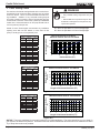
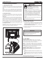
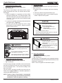
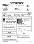
R
CASTILE PELLET INSERT
Owner’s Manual
Tested and
Listed by
Installation and Operation
O-T L
C
Portland
Oregon USA
US
OMNI-Test Laboratories, Inc.
Model:
CASTILEI-MBK
CASTILEI-PMH
CASTILEI-CSB
CASTILEI-CWL
NOTICE
• Important operating and • Read, understand and • Leave this manual with
follow these instrucparty responsible for use
maintenance instructions
for
safe
installaand operation.
tions included.
tion and operation.
WARNING
WARNING
Please read this entire manual
before installation and use of this
pellet fuel-burning room heater.
Failure to follow these instructions
could result in property damage,
bodily injury or even death.
• Do not store or use gasoline or other flam-
mable vapors and liquids in the vicinity of this
or any other appliance.
• Do not overfire - If any external part starts to
glow, you are overfiring. Reduce feed rate.
Overfiring will void your warranty.
• Comply with all minimum clearances to combustibles as specified. Failure to comply may
cause house fire.
HOT SURFACES!
Glass and other surfaces are
hot during operation AND
cool down.
Hot glass will cause burns.
• Do not touch glass until it is cooled
• NEVER allow children to touch glass
• Keep children away
• CAREFULLY SUPERVISE children in same room as
fireplace.
• Alert children and adults to hazards of high
temperatures.
High temperatures may ignite clothing or other
flammable materials.
• Keep clothing, furniture, draperies and other flammable
materials away.
CAUTION
CAUTION
Tested and approved for wood pellets and shelled
field corn fuel only. Burning of any other type of fuel
voids your warranty.
www.quadrafire.com
T
O
N RD
O A
D SC
I
D
DO NOT DISCARD THIS MANUAL
Check building codes prior to installation.
• Installation MUST comply with local, regional, state and national
codes and regulations.
• Consult local building, fire officials or authorities having jurisdiction about restrictions, installation inspection, and permits.
7022-122
January 19, 2011
Castile Pellet Insert
R
and Welcome to the Quadra-Fire Family!
Hearth & Home Technologies welcomes you to our tradition of
excellence! In choosing a Quadra-Fire appliance, you have our
assurance of commitment to quality, durability, and performance.
This commitment begins with our research of the market,
including ‘Voice of the Customer’ contacts, ensuring we make
products that will satisfy your needs. Our Research and Development facility then employs the world’s most advanced technology to achieve the optimum operation of our stoves, inserts
and fireplaces. And yet we are old-fashioned when it comes to
craftsmanship. Each unit is meticulously fabricated and surfaces
are hand-finished for lasting beauty and enjoyment. Our pledge
to quality is completed as each model undergoes a quality control
inspection.
We wish you and your family many years of enjoyment in the
warmth and comfort of your hearth appliance. Thank you for
choosing Quadra-Fire.
NOTE: Consult insurance carrier, local building inspector, fire
officials or authorities having jurisdiction over restrictions,
installation inspection and permits.
LOCATION: Riveted to appliance behind left side panel. Remove cast side and swing label forward
Test Lab &
Report No.
Model
SAFETY LABEL / ÉTIQUETTE DE SÉCURITÉ
Appareil de chauffage inséré de combustible solide/de type de boulettes. “Pour Usage Avec Bois Solide et
Champ de Maïs égrené Seulement”. Accepté dans l'installation dans les maisons mobiles. Cet appareil a
été testé et enregistré pour l'usage dans les Maisons Mobiles en accord avec OAR 814-23-9000 jusqu'à
814-23-909.
Testé à: ASTM #1509-04, ULC S628-93, ULC/ORD-C1482-M1990 Room Heating. Pellet Burning Type, UM)
84-HUD POUR USAGE AVEC LES BOULETTES DE BOIS. OMNI-Test Laboratories, Inc. a déterminé que cet
appareil se conforme avec la norme de l’Association Canadienne de normalisation (CSA) B415.1 ainsi que le Titre 40 du
Code Fédéral de Régulations des États-Unis, partie 60, sous-partie AAA. Accréditations OMNI-Test Laboratories : Le
Conseil Canadien des Normes (CCN/SCC), l’Institue des Standards Nationaux Américain (ANSI) et l’Agence de Protection
Environnemental (EPA).
Puissance de Rendement: 30,000 BTU/HR
Puissance Électrique: 115 VAC, 60 Hz, Début 4.1 Amps, Courir 1.1 Amps,
Éloignez le fil électrique de l'appareil. Ne pas faire passer le fil électrique au dessus ou en dessous de l'appareil.
DANGER: Il y a risque de décharge électrique. Déconnectez le fil électrique de la prise de contact avant le service.
Remplacez la vitre seulement avec une vitre céramique de 5 mm disponible chez votre fournisseur.
Pour allumer, monter la température du thermostat au dessus de la température de la pièce, le poêle s'allumera
automatiquement. Pour éteindre, descendre la température du thermostat en dessous de la température de la pièce.
Pour des instructions supplémentaires, référez vous au manuel du propriétaire. Gardez la porte d'ouverture et la porte
des cendres fermées hermétiquement durant l'opération.
Installez et utilisez en accord avec les instructions d'installation et d'opération du fabricant. Contactez le bureau
de la construction ou le bureau des incendies au sujet des restrictions et des inspections d'installation dans votre
voisinage. Ne pas obstruez l'espace en dessous de l'appareil.
A
S
AVIS - Pour Les Maisons Mobiles: Ne pas installer dans une chambre à coucher. Un tuyau extérieur de
combustion d'air doit être installé et ne doit pas être obstrué lorsque l'appareil est en usage. La structure
intégrale du plancher, du plafond et des murs de la maison mobile doit être maintenue intacte.
Référez vous aux instructions du fabricant et des codes locaux pour les précautions requises pour passer une
cheminée à travers un mur ou un plafond combustibles, et les compensations maximums.
Inspectez et nettoyez la cheminée fréquemment.
Ne pas connecter cet appareil à une cheminée servant un autre appareil.
Utilitsez le système de ventilation de 3 or 4 inch (76-102mm) de diametre de type “L” ou “PL”.
SERIAL NO. / NUMÉRO DU SÉRIE
Listed Solid Fuel Room Heater/Pellet Type Insert. “For Use with Solid Wood Fuel and
Shelled Field Corn Only”. Also suitable for Mobile Home Installation. This appliance has been
tested and listed for use in Manufactured Homes in accordance with OAR 814-23-9000
through 814-23-909.
Tested to: ASTM E1509-04, ULC S628-93, ULC/ORD-C1482-M1990 Room Heating Pellet
Burning Type, (UM) 84-HUD FOR USE ONLY WITH PELLETIZED WOOD. OMNI-Test
Laboratories, Inc. has determined that this appliance complies with Canadian Standards
Association (CSA) B415.1 and Title 40 of the U.S. Code of Federal Regulations, Part 60,
SubPart AAA.OMNI-Test Laboratories Accrediations: The Standards Council of Canada,
the American National Standards Institute, and the U.S. Environmental Protection Agency.
Input Rating: 30,000 BTU/HR.
Electrical Rating: 115 VAC, 60 Hz, Start 4.1 Amps, Run 1.1 Amps.
Route power cord away from unit. Do not route cord under or in front of appliance.
DANGER: Risk of electrical shock. Disconnect power supply before servicing.
Replace glass only with 5mm ceramic available from your dealer.
To start, set thermostat above room temperature, the stove will light automatically. To
shutdown, set thermostat to below room temperature. For further instruction refer to owner's
manual.
Keep viewing and ash removal doors tightly closed during operation.
LE
P
M
PRÉVENTION DES FEUX DE MAISON
PREVENT HOUSE FIRES
Install and use only in accordance with manufacturer's installation and operating instructions.
Contact local building or fire officials about restrictions and inspection in our area.
WARNING: FOR MOBILE HOMES: Do not install appliance in a sleeping room. An outside
combustion air inlet must be provided. The structural integrity of the mobile home floor, ceiling
and walls must be maintained.
Refer to manufacturer's instructions and local codes for precautions required for passing
chimney through a combustible wall or ceiling. Inspect and clean vent system frequently in
accordance with manufacturer's instructions.
DO NOT CONNECT THIS UNIT TO A CHIMNEY SERVING ANOTHER APPLIANCE.
Use a 3 or 4 inch (76-102mm) diameter type "L" or "PL" venting system.
MINIMUM CLEARANCES TO COMBUSTIBLE MATERIALS
Sidewall / Mur Latéral
ESPACES LIBRES MINIMUM DES MATÉRIAUX COMBUSTIBLES:
Masonry or Zero Clearance
Dégagement de la maçonnerie ou Dégagement zéro
AS A BUILT-IN UNIT COMME APPAREIL INSÉRÉ
Maximum Mantel Depth - 10 inches
Profondeur Maximale Mantel - 254mm
A 0 in. 0mm
*Top Vent / Des Conduits Du Haut
G 2 in. (51mm)*
Mantel/Manteau
B 12 in. 305mm
G
I
J
2.5 in. (64mm)** **Rear Vent / Des Conduits Arrières
C 0 in. 0mm
Fascia or Trim
H
H
B
Garniture
H 2 in. (51mm)
D 0 in. 0mm
I
de façade
C
I 4 in. (102mm)
E 6 in. 152mm
K
A
J 3 in. (76mm)
F 6 in. 152mm
Insert
Insére
F
D
E
0 in. Clearance To Exposed Section and Face Trim / Espace libre
de 0 mm de la section exposée et de la garniture du devant.
Mfg By:
Page 2
7022-122
Serial Number
00702300000
R
Castile Pellet Insert-B
Tested and
Listed by
O-T L
C
Portland
Oregon USA
US
OMNI-Test Laboratories, Inc.
Report / Rapport
#061-S-77d-6.2
Made in U.S.A. of US and
imported parts.
États-Unis-d’Amérique par des
pièces d’origine américaine et
pièces importées.
Manufactured by: Fabriqué par:
1445 Highway North, Colville, WA 99114
www.quadrafire.com
2010 2011 2012
JAN
FEB MAR
APR MAY JUNE
JULY AUG SEPT
OCT
NOV DEC
DO NOT REMOVE THIS LABEL
NE PAS ENLEVER L'ÉTIQUETTE
Mfg Date
7022-121
January 19, 2011
R
Castile Pellet Insert
Safety Alert Key:
•
DANGER! Indicates a hazardous situation which, if not avoided will result in death or serious injury.
•
WARNING! Indicates a hazardous situation which, if not avoided could result in death or serious injury.
•
CAUTION! Indicates a hazardous situation which, if not avoided, could result in minor or moderate injury.
•
NOTICE: Indicates practices which may cause damage to the fireplace or to property.
TABLE OF CONTENTS
Section 1: Listing and Code Approvals
A.
B.
C.
D.
E.
Appliance Certifications ......................4
Mobile Home Approved ......................4
Glass Specifications ............................4
Electrical Rating ..................................4
BTU & Efficiency Specifications ..........4
Section 7: Appliance Set-Up
A.
B.
C.
D.
E.
F.
G.
H.
I.
J.
Section 2: Getting Started
A. Design, Installation & Location
Considerations ....................................5
B. Locating Your Appliance & Chimney ..6
C. Draft ....................................................6
D. Negative Pressure ..............................6
E. Avoiding Smoke & Odors....................7
F. Fire Safety ..........................................8
G. Tools & Supplies Needed ...................8
H. Inspect Appliance, Components
and Pre-Burn List ................................8
Section 8: Operating Instructions
A.
B.
C.
D.
E.
F.
G.
H.
I.
J.
Section 3: Dimensions & Clearances
A. Appliance Dimensions ........................9
B. Clearances to Combustibles
As A Built-In, UL and ULC ..................10
C. Clearances to Combustibles,
Masonry & Zero Clearance .................11
D. Minimum Opening for Masonry and
Factory-Built Fireplace ........................11
E. Floor Protection ..................................11
F. Prefabricated Metal Chimney ..............11
G. Removing Floor of Factory Built
Fireplace .............................................12
H. Altering Factory-Built Fireplace ...........12
Section 10: Maintaining & Servicing Appliance
A.
B.
C.
D.
E.
F.
G.
H.
I.
A.
Section 5: Venting Systems
Proper Shutdown Procedures .............32
Quick Reference Maintenance Chart ..32
General Maintenance & Cleaning .......32-35
High Ash Content Maintenance ..........36
Combustion Blower Replacement .......37
Convection Blower Replacement ........37
Igniter Replacement ............................38
Glass Replacement .............................38
Baffle & Brick Removal .......................39-40
Section 12: Reference Material
A.
B.
C.
D.
E.
F.
G.
H.
A. Full Reline with Outside Air-Horizontal 15
B. Full Reline with Outside Air-Vertical ....16
Section 6: Mobile Home ..................................17
January 19, 2011
Combustible & Non-Combustible ........25
Fuel Material & Fuel Storage ..............25
General Operation Information ...........26
Before Your First Fire .........................26
Clear Space ........................................26
Starting Your First Fire........................27
Fire Characteristics .............................27
Feed Rate Adjustment .......................27
Ignition Cycles ....................................28
Frequently Asked Questions...............28
Section 9: Troubleshooting ............................29-31
Section 4: Vent Information
Chimney & Exhaust Connections ........13
B. Venting Termination Requirements ....13
C. Pellet Venting Chart ............................14
Leveling System .................................18
Outside Air Kit .....................................18
Door Handle Removal ........................19
Door Removal .....................................19
Adjustable Hearth Support ..................19
Hearth Support, Standard Surround ...20-21
Surround & Trim Set, Econo ...............21
Surround Cast Trim Set ......................22
Log Set Placement ..............................22
Thermostat Installation ........................24
7022-122
Component Functions.........................40-42
Component Locations .........................43
Exploded Drawings .............................44
Service Parts & Accessories ...............45-50
Maintenance & Service Log ................51-52
Homeowner’s Notes ............................53
Warranty Policy ...................................54-55
Contact Information .............................56
Page 3
Castile Pellet Insert
1
R
Listing and Code Approvals
A. Appliance Certification
E. BTU & Efficiency Specifications
MODEL:
Castile Pellet Insert-B
LABORATORY:
OMNI Test Laboratories, Inc
REPORT NO.
061-S-77d-6.2
TYPE:
Solid Fuel Room Heater/Pellet Fuel
Burning Type Insert
STANDARD:
ASTM E1509-2004, ULC S628-93 and
ULC/ORD-C1482-M1990 Room Heater
Pellet Fuel Burning Type and (UM) 84HUD, Mobile Home Approved
NOTE: This installation must conform with local codes. In
the absence of local codes you must comply with the ASTM
E1509-2004, ULC S628-93, ULC/ORD-C-1482-M1990,
(UM) 84-HUD
The Castile Pellet Insrt by Quadra-Fire is exempt from Environmental Protection Agency certification under 40 CFR
60.531 y definition [Wood Heater (A) “Air to Fuel Ratio].
B. Mobile Home Approved
This appliance is approved for mobile home installations
when not installed in a sleeping room and when an outside
combustion air inlet is provided.
The structural integrity of the mobile home floor, ceiling, and
walls must be maintained. The appliance must be properly
grounded to the frame of the mobile home and use only listed
pellet vent, Class “L” or “PL” connector pipe.
A Quadra-Fire Outside Air Kit must be installed in a mobile
home installation.
Note: This appliance is also approved for installation
into a shop.
Particulate
Emissions Rating:
0.7 grams/hr
*BTU Output:
8,000 - 30,000 / hr
Heating Capacity:
up to 1,500 sq. ft. depending
on climate zone
Hopper Capacity:
45 lbs
Fuel:
Wood Pellets or Shelled Corn
Shipping Weight:
252 lbs
*BTU output will vary, depending on the brand of fuel you
use in your appliance. Consult your Quadra-Fire dealer
for best results.
WARNING! Risk of Fire! Hearth & Home Technologies disclaims any responsibility for, and the warranty and agency
listing will be voided by the below actions.
DO NOT:
• Install or operate damaged appliance
• Modify appliance
• Install other than as instructed by Hearth & Home
Technologies
• Operate the appliance without fully assembling all
components
• Overfire
• Install any component not approved by Hearth &
Home Technologies
• Install parts or components not Listed or approved.
• Disable safety switches
Improper installation, adjustment, alteration, service or
maintenance can cause injury or property damage.
For assistance or additional information, consult a qualified
installer, service agency or your dealer.
C. Glass Specifications
This appliance is equipped with 5mm ceramic glass.
Replace glass only with 5mm ceramic glass. Please contact
your dealer for replacement glass.
D. Electrical Rating
115 VAC, 60 Hz, Start 4.1 Amps, Run 1.1 Amps
NOTE: Some generator or battery back-up systems may
not be compatible with the micro-processor electronics on this appliance. Please consult the power supply
manufacturer for compatible systems.
Page 4
NOTE: Hearth & Home Technologies, manufacturer of
this appliance, reserves the right to alter its products,
their specifications and/or price without notice.
Quadra-Fire is a registered trademark of Hearth & Home
Technologies.
7022-122
January 19, 2011
R
Castile Pellet Insert
2
Getting Started
A. Design, Installation & Location Considerations
Since pellet exhaust can contain ash, soot or sparks, you
must consider the location of:
1. Appliance Location
• Windows
NOTICE: Check building codes prior to installation.
• Installation MUST comply with local, regional, state and
national codes and regulations.
• Air Conditioner
•
Consult insurance carrier, local building inspector, fire
officials or authorities having jurisdiction over restrictions,
installation inspection and permits.
It is a good idea to plan your installation on paper, using
exact measurements for clearances and floor protection,
before actually beginning the installation
Consideration must be given to:
• Safety, convenience, traffic flow
• Placement of the chimney and chimney connector.
• If you are not using an existing chimney, place the appliance where there will be a clear passage for a factorybuilt listed chimney through the ceiling and roof.
• Installing an optional outside air kit would affect the location of the vent termination.
Recommended Location:
• Above peak
• Air Intakes
• Overhang, soffits, porch roofs, adjacent walls
• Landscaping, vegetation
When locating vent and venting termination, vent above
roof line when possible.
Warning! Risk of Fire Damaged parts could impair safe
operation. Do NOT install damaged, incomplete or substitute
components.
CAUTION! If burning shelled field corn, you must use approved venting specifically designed for corn to prevent corrosion or degradation. Follow the instructions from the venting
manufacturer.
NOTICE: Locating the appliance in a location of
considerable air movement can cause intermittent smoke
spillage from appliance. Do not locate appliance near:
•
Frequently open doors
•
Central heat outlets or returns
Recommended Location:
• Above peak
• Inside heated space
Marginal Location:
• Wind loading possible
Marginal Location:
• Below peak
Location NOT recommended:
• Not the highest point of the roof
• Wind loading possible
Recommended:
• Insulated exterior chase
in cooler climates
Location NOT recommended:
• Too close to tree
• Below adjacent structure
• Lower roof line
• Avoid outside wall
Windward
Leeward
Recommended:
Outside Air Intake
on windward side
Multi-level Roofs
NOT recommended:
Outside Air Intake
on leeward side
Figure 5.1
January 19, 2011
7022-122
Page 5
Castile Pellet Insert
R
B. Locating Your Appliance & Chimney
D. Negative Pressure
Location of the appliance and chimney will affect
performance.
WARNING! Risk of Asphyxiation! Negative pressure can
cause spillage of combustion fumes and soot.
•
Install through the warm airspace enclosed by the building
envelope. This helps to produce more draft, especially
during lighting and die-down of the fire.
•
Penetrate the highest part of the roof. This minimizes the
effects of wind loading.
•
Locate termination cap away from trees, adjacent
structures, uneven roof lines and other obstructions.
•
Exhaust fans (kitchen, bath, etc.)
•
Range hoods
•
Minimize the use of chimney offsets.
•
•
Consider the appliance location relative to floor and ceiling
and attic joists.
Combustion air requirements for furnaces, water heaters
and other combustion appliances
•
Clothes dryers
•
Location of return-air vents to furnace or air conditioning
•
Imbalances of the HVAC air handling system
•
Upper level air leaks such as:
CAUTION
Negative pressure results from the imbalance of air available for the appliance to operate properly. It can be strongest in lower levels of the house.
Causes include:
• DO NOT CONNECT THIS UNIT TO A CHIMNEY FLUE
SERVICING ANOTHER APPLIANCE.
- Recessed lighting
• DO NOT CONNECT TO ANY AIR DISTRIBUTION DUCT
OR SYSTEM.
May allow flue gases to enter the house
- Duct leaks
- Attic hatch
To minimize the effects of negative air pressure:
C. Draft
Draft is the pressure difference needed to vent appliances
successfully. When an appliance is drafting successfully, all
combustion byproducts are exiting the home through the
chimney.
Considerations for successful draft include:
•
Preventing negative pressure
•
Location of appliance and chimney
To measure the draft or negative pressure on your appliance
use a magnahelic or a digital pressure gauge capable of
reading 0 - .25 inches of water column (W.C.).
The appliance should be running on high for at least 15
minutes for the test.
With the stove running on high you should have a negative
pressure equal to or greater than the number given in the
chart below. If you have a lower reading than you find on the
chart, your appliance does not have adequate draft to burn
the fuel properly.
Minimum Vacuum Requirements:
Page 6
•
Install the outside air kit with the intake facing prevailing
winds during the heating season
•
Ensure adequate outdoor air for all combustion appliances
and exhaust equipment
•
Ensure furnace and air conditioning return vents are not
located in the immediate vicinity of the appliance
•
Avoid installing the appliance near doors, walkways or
small isolated spaces
•
Recessed lighting should be a “sealed can” design
•
Attic hatches weather stripped or sealed
•
Attic mounted duct work and air handler joints and seams
taped or sealed
NOTICE: Hearth & Home Technologies assumes no
responsibility for the improper performance of the chimney
system caused by:
• Inadequate draft due to environmental conditions
•
Downdrafts
•
•
Tight sealing construction of the structure
Mechanical exhausting devices
.095
7022-122
January 19, 2011
R
Castile Pellet Insert
E. Avoiding Smoke and Odors
Vent Configurations
Negative Pressure, Shut-Down and Electrical Power
Failure
To reduce the probability of back-drafting or burn-back in
the pellet appliance during power failure or shut down conditions, it must be able to draft naturally without exhaust
blower operation.
Negative pressure in the house will resist this natural draft
if not accounted for in the pellet appliance installation.
Heat rises in the house and leaks out at upper levels. This
air must be replaced with cold air from outdoors which
flows into lower levels of the house.
Vents and chimneys into basements and lower levels of the
house can become the conduit for air supply and reverse
under these conditions.
Outside Air
To reduce probability of reverse drafting during shut-down
conditions Hearth & Home Technologies strongly recommends:
•
Installing the pellet vent with a minimum vertical run of
5 feet (1.52m). Preferably terminating above the roof
line.
•
Installing the outside air kit at least 4 feet (1.22m)
below the vent termination.
To prevent soot damage to exterior walls of the house and
to prevent re-entry of soot or ash into the house:
•
Maintain specified clearances to windows, doors and
air inlets, including air conditioners.
•
Vents should not be placed below ventilated soffits.
Run the vent above the roof.
•
Avoid venting into alcove locations.
An outside air kit is recommended in all installations. The
Outside Air Kit must be ordered seperately.
•
Vents should not terminate under overhangs, decks or
onto covered porches.
Per national building codes, consideration must be given
to combustion air supply to all combustion appliances.
Failure to supply adequate combustion air for all appliance
demands may lead to backdrafting of those and other
appliances.
•
Maintain minimum clearance of 6 inches (152mm)
from the vent termination to the exterior wall. If you
see deposits developing on the wall, you may need to
extend this distance to accommodate your installation
conditions.
When the appliance is roof vented (strongly recommended):
The air intake is best located on the exterior wall oriented towards the prevailing wind direction during the
heating season.
When the appliance is side-wall vented:
The air intake is best located on the same exterior wall
as the exhaust vent outlet and located lower on the wall
than the exhaust vent outlet.
The outside air supply kit can supply most of the demands
of the pellet appliance, but consideration must be given to
the total house demand.
House demand may consume the air needed for the appliance. It may be necessary to add additional ventilation to
the space in which the pellet appliance is located.
Consult with your local HVAC professional to determine
the ventilation demands for your house.
January 19, 2011
7022-122
Page 7
Castile Pellet Insert
R
F. Fire Safety
H. Inspect Appliance & Components
To provide reasonable fire safety, the following should be
given serious consideration:
• Remove appliance and components from packaging
and inspect for damage.
• Install at least one smoke detector on each floor of your
home.
• Report to your dealer any parts damaged in shipment.
• Locate smoke detector away from the heating appliance
and close to the sleeping areas.
• Follow the smoke detector manufacturer’s placement and
installation instructions and maintain regularly.
• Read all the instructions before starting the installation. Follow these instructions carefully during
the installation to ensure maximum safety and
benefit.
• Conveniently locate a Class A fire extinguisher to contend
with small fires.
•
WARNING
In the event of a hopper fire:
Inspect appliance and components for
damage. Damaged parts may impair safe
operation.
• Do NOT install damaged components.
• Do NOT install incomplete components.
• Do NOT install substitute components.
• Evacute the house immediately.
• Notify fire department.
Report damaged parts to dealer.
WARNING
Fire Risk.
Pre-Burn Check List
Hearth & Home Technologies disclaims any
responsibility for, and the warranty will be
voided by, the following actions:
• Installation and use of any damaged appliance.
• Modification of the appliance.
• Installation other than as instructed by Hearth & Home
Technologies.
• Installation and/or use of any component part not approved
by Hearth & Home Technologies.
• Operating appliance without fully assembling all
components.
• Do NOT Overfire.
Or any such action that may cause a fire hazard.
G. Tools And Supplies Needed
Tools and building supplies normally required
for installation, unless installing into an existing
masonry fireplace:
Reciprocating Saw
Hammer
Phillips Screw driver
Tape Measure
Plumb Line
Level
Framing Material
Non-Combustible Sealant
Material
Page 8
Gloves
Safety Glasses
Framing Square
Electric Drill & Bits)
1/4” Self-Tapping Screws
May also need:
Vent Support Straps
Venting Paint
1.
Place the appliance in a location near the
final installation area and follow the procedures below:
2.
Open the appliance and remove all the parts
and articles packed inside the Component
Pack. Inspect all the parts and glass for shipping damage. Contact your dealer if any irregularities are noticed.
3.
All safety warnings have been read and followed.
4.
This Owner’s Manual has been read.
5.
Floor protection requirements have been met.
6.
Venting is properly installed.
7.
The proper clearances from the appliance and
chimney to combustible materials have been
met.
8.
The masonry chimney is inspected by a professional and is clean, or the factory built metal
chimney is installed according to the manufacturer’s instructions and clearances.
9.
The chimney meets the required minimum
height.
10.
All labels have been removed from the glass
door.
11.
Plated surfaces have been wiped clean, if
applicable.
12.
Thermostat or remote has been installed.
13.
A power outlet is available nearby.
14.
A good quality surge protection is highly recommended to protect the electronics.
7022-122
January 19, 2011
R
3
Castile Pellet Insert
Dimensions and Clearances
A. Appliance Dimensions
27-7/8 in. (707mm)
23-3/8 in. (594mm)
8 in.
(203mm)
24-3/4 in.
(629mm)
19 in.
(483mm)
9-3/4 in.
(249mm)
13 in.
(330mm)
2 in.
(51mm)
32-1/4 in. (819mm)
Figure 9.1 - Top View
Figure 9.2 -Side View
A
B
Figure 9.3- Front View
Overall Size
January 19, 2011
A
B
Metal Surround w/Cast Trim, STD
42-1/2 in. (1080mm)
30 in. (762mm)
Metal Surround w/Cast Trim, LRG
48 in. (1219mm)
34 in. (864mm)
Metal Surround w/Standard Trim, STD
43 in. (1092mm)
31 in. (787mm)
Metal Surround w/Standard Trim, LRG
51 in. (1294mm)
34 in. (864mm)
7022-122
Page 9
Castile Pellet Insert
R
NOTE: All Clearances are Minimum Clearances
B. Clearance To Combustibles, UL and ULC
AS A BUILT-IN
A
C
D
B
C
B
0 in. Clearance To Exposed Section And Face Trim
Figure 10.1
A
Must be installed in a non-tapered enclosure.
Top of Hopper
Inches
Millimeters
Top Vent
2.0
51
Rear Vent
2.5
64
Top or Rear Vent
2.0
51
B
Side of Hopper
C
Back of Hopper
Top or Rear Vent
4.0
102
D
Vent Pipe to Combustible
Top or Rear Vent
3.0
76
INSTALLED AS A BUILT-IN UNIT
Shown with Rear Vent and Outside Air
WARNING
Combustible
Mantel
Fire Risk.
Comply with all minimum clearances to combustibles as specified.
12 in
(305mm)
Top Vent:
2 in. (51mm)
Rear Vent:
2.5 in (64mm)
6 in
(152mm)
Back of Hopper:
4 in (102mm)
Vent Pipe to
Combustibles:
3 in (76mm)
Outside Air
Failure to comply may cause
house fire.
NOTE:
• Illustrations reflect typical installations
and are FOR DESIGN PURPOSES
ONLY.
• Illustrations/diagrams are not drawn to
scale.
• Actual installation may vary due to
individual design preference.
Figure 10.2
Page 10
7022-122
January 19, 2011
R
Castile Pellet Insert
C. Masonry and Factory-Built Fireplaces
E. Floor Protection
Maximum Mantel Depth: 12 inches (305mm)
Face
Trim
Mantel
B
Millimeters
E
Floor protection hearth extension from
door opening
6
152
F
Floor protection to the side of door
opening
6
152
C
Side Wall
Inches
F. Prefabricated Metal Chimney
The chimney can be new or existing, masonry or prefabricated
and must meet the following minimum requirements:
D
A
• Must be minimum 6 inch (152mm) inside diameter of
high temperature chimney listed to UL 103 HT (2100oF)
or ULC-S628.
E
F
• Must use components required by the manufacturer for
installation.
Figure 11.1
Inches
Millimeters
A Insert side to combustible side wall
16
406
B Insert top to mantel
12
305
C Insert top to maximum. 2-1/4 inch
4-3/4
121
D Insert side to maximum. 2-1/4 inch
10
254
(57mm) face trim
(57mm) face trim
D. Minimum Opening for Masonry and
Factory-Built Fireplaces
• Must maintain clearances required by the manufacturer
for installation.
• Refer to manufacturers instructions for installation
•This insert is listed to UL 1482 Standard and is approved
for installation into listed factory-built zero clearance fireplaces listed to UL 127 conforming to the following specifications and instructions:
•The original factory-built zero clearance fireplace chimney cap must be re-installed after installing the approved
chimney liner meeting type UL 103 HT requirements
(2100°F) per UL 1777.
•If the chimney is not listed as meeting HT requirements,
or if the factory built fireplace was tested prior to 1998, a
full height listed chimney liner must be installed from the
appliance flue collar to the chimney top.
•The liner must be securely attached to the insert flue collar
and the chimney top.
B
•The air flow of the factory-built zero-clearance fireplace
system must not be altered. The flue liner top support
attachment must not reduce the air flow for the existing
air-cooled chimney system.
C
•No dilution air is allowed to enter the chimney.
A
1. Secure the fireplace damper in the open position. If
this cannot be accomplished, it will be necessary to
remove the damper.
D
2. Seal damper area of chimney around chimney
connector with a high temperature sealant or seal
insert against the face of the fireplace.
Figure 11.2
Location
Inches
Millimeters
A
Rear Width
23-5/8
600
B
Depth
17
432
C
Height
21-1/4
540
D
Front Width
28-1/8
714
January 19, 2011
3. Both methods must be removable and replaceable
for cleaning and re-installation.
7022-122
Page 11
Castile Pellet Insert
R
G. Removing Metal Floor of Factory-Built Fireplace
• The firebrick (refractory), glass doors, screen rails, screen
mesh and log grates can be removed from a factory-built firebox in order to gain minimum insert opening requirements.
• Any smoke shelves, shields and baffles may be removed
from a factory-built firebox if attached with mechanical fasteners.
• The metal floor of the factory-built fireplace may be removed
to facilitate the installation of the insert only when a 1/4 (6mm)
inch airspace is provided between the insert and the floor of
outer wrap.
• This should have prior approval from authority having jurisdiction. Upon removal, the factory built fireplace is no longer
considered a UL 127 Listed fireplace, only a metal box.
• Ensure the metal box is supported to hold weight of the chimney and the insert. Maintain clearances to combustibles.
The following is only one example as there are many different
models of factory-built fireplaces.
In Figure 2.3 Ensure that the power cord can not be damaged
by the sharp metal edge. You may need to cut out a notch to
accommodate the cord.
NOTE: If the floor is made of thin metal, we recommend
using the 2 x 4 from the insert packaging to support the insert.
The 2 x 4 may need to be cut to the appropriate size. Ensure
that the leveling bolt is positioned over the 2 x 4 before leveling the insert.
H. Altering the Factory-Built Fireplace
•
The fireplace must not be altered, except for the
exceptions listed below. Do not removal the bricks and
mortar from the existing fireplace.
The following modifications are premissible:
•
•
•
•
•
•
Starter hole
•
External trim pieces which do not affect the operation
of the fireplace may be removed providing they can be
stored on or within the fireplace for reassembly if the
insert is removed.
•
The permanent metal warning label provided must be
attached to the back of the fireplace, with screws or
nails, stating that the fireplace may have been altered
to accommodate the insert, and the fireplace must be
returned to original condition befor use as a conventional
fireplace. Figure 12.4.
•
If the hearth extension is lower than the fireplace
opening, the portion of the insert extending onto the
hearth must be supported.
•
Manufacturer designed adjustable support kit can be
ordered from your dealer.
•
Final approval of this installation type is contingent upon
the authority having jurisdiction.
Mark area of
floor to cut
Figure 12.1. Measure and mark the metal floor for cutting. With
a drill, make a starter hole in each corner.
Figure 12.2. Using a saws-all, cut out the floor.
Removal of damper or locked in open position
Removal of smoke shelf or baffle
Removal of ember catches
Removel of fire grate
Removal of view screen/curtain
Removal of doors
NOTE: Refer to chimney liner manufacturer for recommendations on supporting the liner. Installation
into fireplaces without a permit will void the listing
WARNING
THIS FIREPLACE MAY HAVE BEEN ALTERED
TO ACCOMMODATE AN INSERT. IT MUST BE
RETURNED TO ITS ORIGINAL CONDITION
BEFORE USE AS A SOLID FUEL BURNING
FIREPLACE.
250-2061
250-2061
Figure 12.4
Figure 12.3. Using a saws-all, cut out the floor.
Page 12
7022-122
January 19, 2011
R
4
Castile Pellet Insert
Vent Information
B. Venting Termination Requirements
A. Chimney and Exhaust Connection
1. Chimney & Connector: Use 3 or 4 inch (76-102mm)
diameter type "L" or "PL" venting system. It can be vented
vertically or horizontally.
2. Mobile Home: Approved for all Listed pellet vent. Use Listed
double wall flue connector. A Quadra-Fire outside air kit must
be used with manufactured home installations.
3. Residential: Use 24 gauge single wall flue connector or
Listed double wall flue connector to Class A Listed metal
chimneys, or masonry chimneys meeting International Building Code (ICC) standards for solid fuel appliances.
CAUTION
Do not terminate vent in any enclosed or semi-enclosed
area such as a carport, garage, attic, crawl space, under a
sun deck or porch, narrow walkway or closely fenced area,
or any location that can build up a concentration of fumes
such as a stairwell, covered breezeway, etc.
1. Termination must exhaust above air inlet elevation. It
is strongly recommended that at least 60 inches
(1524mm) of vertical pipe be installed when appliance is vented directly through a wall. This will create
a natural draft, which will help prevent the possibility of
smoke or odor venting into the home during a power
outage. It will also keep exhaust from causing a nuisance or hazard by exposing people or shrubs to high
temperatures. The safest and preferred venting method
is to extend the vent vertically through the roof.
4. INSTALL VENT AT CLEARANCES SPECIFIED BY THE
VENT MANUFACTURER.
5. Secure exhaust venting system to the appliance with at least
3 screws. Also secure all connector pipe joints with at least
3 screws through each joint.
6. DO NOT INSTALL A FLUE DAMPER IN THE EXHAUST
VENTING SYSTEM OF THIS UNIT.
7. DO NOT CONNECT THIS UNIT TO A CHIMNEY FLUE
SERVING ANOTHER APPLIANCE.
NOTE: All pipe must be welded seam pipe whenever possible. Seal pipe joints with high temperature silicone (500°F
[260°C] minimum rated only).
NOTE: If burning shelled field corn, you must use approved
venting specifically designed for corn. Follow the instructions from the venting manufacturer.
WARNING
Fire Risk.
• Only LISTED venting components may be used.
• NO OTHER vent components may be used.
Substitute or damaged vent components may impair
safe operation.
• Follow venting manufacturer’s clearances
and instructions when installing venting system.
WARNING
Vent surfaces get HOT, can cause burns if
touched. Non-combustible shielding or guards
may be required.
NOTICE: In Canada when using a factory-built chimney it must be safety listed, Type UL103 HT (2100oF)
[1149oC] CLASS “A” or conforming to CAN/ULCS629M, STANDARD FOR 650oC FACTORY-BUILT
CHIMNEYS.
January 19, 2011
2. Distance from doors and opening windows, or gravity or
ventilation air inlets into building:
a. Not less than 48 inches (1219mm) below;
b. Not less than 48 inches (1219mm) horizontally
from;
c. Not less than 12 inches (305mm) above.
3. Distance from permanently closed windows:
a. Not less than 12 inches (305mm) below, horizontally
from or above.
4. Distance between bottom of termination and grade
should be 12 inches (305mm) minimum. This is conditional upon plants in the area, and nature of grade
surface. The grade surface must be a non-combustible
material (i.e., rock, dirt). The grade surface must not be
lawn. Distance between bottom of termination and public
walkway should be 84 inches (2134mm) minimum.
5. Distance to combustible materials must be 24 inches
(610mm) minimum. This includes adjacent buildings,
fences, protruding parts of the structure, roof overhang,
plants and shrubs, etc.
6. Termination Cap Location (Home Electrical Service)
•
Side-to-side clearance is to be the same as minimum
clearance to vinyl inside corners.
•
Clearance of a termination cap below electrical service
shall be the same as minimum clearance to vinyl soffits.
•
Clearance of a termination cap above electrical service
will be 12 inches (305mm) minimum.
•
Location of the vent termination must not obstruct or
interfere with access to the electrical service.
7022-122
Page 13
Castile Pellet Insert
R
C. Pellet Venting Charts
WARNING
The maximum horizontal venting allowed with no vertical venting attached is 48 inches (1219mm) including one 90° elbow
or two 45° elbows. This is our recommended horizontal venting installation. Addition of any horizontal venting beyond
48 inches (1219mm) Hearth & Home Technologies strongly
recommends a minimum of 60 inches (1524mm) of additional
vertical vent. Horizontal sections of vent pipe should have a
1/4 inch (6.35mm) rise per foot.
Fire Risk.
• Only LISTED venting components may be
used.
• NO OTHER vent components may be used.
Substitute or damaged vent components may
impair safe operation.
45° elbow is equivalent to 1 foot of straight pipe
90° elbow is equivalent to 3 feet of straight pipe
Hearth & Home Technologies recommends any installation
requiring more than two 90° elbows, or more than 15 feet
(4.5m) of venting to use 4 inch (102mm) vent.
ONE 90º ELBOW
Minimum
Vertical
0
5
6
7
8
9
10
11
12
13
14
15
16
17
18
19
Vent
Diameter
3
3
3
3
4
4
4
4
4
4
4
4
4
4
4
4
Minimum Vertical Vent for One Elbow
Minimum
Vertical Vent for One Elbow
Minimum Vertical Rise
(ft)
Total
Horizontal
4
5
6
7
8
9
10
11
12
13
14
15
16
17
18
19
Vent
Diameter
3
3
3
3
3
4
4
4
4
4
4
4
4
4
10
5
0
5
10
15
20
Horizontal Run,
Horizontal
Run(ft)(FT)
Figure 14.1
Minimum Vertical
Vertical Vent
for for
TwoTwo
Elbows
Minimum
Vent
Elbows
20
Minimum Vertical
Rise, (ft)
Minimum
Vertical
5
6
7
8
9
10
11
12
13
14
15
16
17
18
15
0
TWO 90º ELBOWS
Total
Horizontal
2
3
4
5
6
7
8
9
10
11
12
13
14
15
20
15
10
5
0
0
5
10
15
of Horizontal
Sections,(FT)
(ft)
LengthLength
of Horizontal
Sections
Figure 14.2
THREE 90º ELBOWS
Minimum
Vertical
11
12
13
14
15
16
17
18
19
20
Vent
Diameter
4
4
4
4
4
4
4
4
4
4
Minimum Vertical
Vertical Vent
for for
Three
Elbows
Minimum
Vent
Three
Elbows
Minimum Vertical Rise
(ft)
Total
Horizontal
2
3
4
5
6
7
8
9
10
11
25
20
15
10
5
0
0
Length
2
4
6
8
10
12
Length
of Horizontal
Sections
(ft)
of
Horizontal
Sections
(FT)
Figure 14.3
NOTICE: These are guidelines for successful venting of your pellet appliance. The more vertical rise you can obtain in
your system, the better it will perform. Horizontal vent runs can accumulate ash and will need to be cleaned more often.
Try to keep them as short as possible.
Page 14
7022-122
January 19, 2011
R
5
Castile Pellet Insert
Venting Systems
A. Full Reline With Horizontal Outside Air
WARNING
Fire Risk.
Inspection of Chimney:
• Masonry chimney must be in good condition.
• Meets minimum standard of NFPA 211
• Factory-built chimney must be a minimum 6 inch
(152mm) UL103 HT.
CAUTION
Never draw outside combustion air from:
• Wall, floor or ceiling cavity
• Enclosed space such as an attic or garage
NOTE; Use metal plate around
exhaust vent pipe and seal all
edges with non-flammable insulation such as , mineral wool or
ceramic.
Do not use high temperature
caulking materials to seal any
edge to prevent future serviceability.
Outside Air through Rear
Wall (Horizontal)
Figure 15.1
NOTE:
In Canada, where passage through a wall or partition of
combustible construction is desired, the installation shall
conform to CAN/CSA-B365.
January 19, 2011
NOTE:
• Illustrations reflect typical installations and are FOR
DESIGN PURPOSES ONLY.
• Illustrations/diagrams are not drawn to scale.
• Actual installation may vary due to individual design
preference.
7022-122
Page 15
Castile Pellet Insert
R
C. Full Reline With Vertical Outside Air
NOTE: Check clearances carefully for this type of
installation to ensure adequate room for outside air
venting.
CAUTION
Check building codes prior to installation.
• Installation MUST comply with local, regional, state and
national codes and regulations.
• Consult local building, fire officials or authorities having
jurisdiction about restrictions, installation inspection,
and permits.
12” (305mm)
min. above
12” (305mm)
min. below
NOTE: In Canada, only a full reline is allowed per
ULC S628-93, ORD ULC C1482-M1990.
NOTE: In Canada this fireplace insert must be installed
with a continous chimney liner a 6 inch (152mm) in
diameter extending from the fireplace insert to the top
of the chimney. The chimney liner must conform to the
Class 3 requirments of CAN/ULC-S635, Standard for
Lining Systems for Existing Masonry or Factory-Built
Chimneys and Vents, or CAN/ULC-S640, Standard for
Lining Systems for New Masonry Chimneys.
NOTE; Use metal
plate around
exhaust vent pipe
and seal all edges
with non-flammable
insulation such as
mineral wool or
ceramic.
Do not use high
temperature caulking materials to seal
any edge to prevent
future serviceability
Outside Air
Termination
at
Chimney Top
Figure 16.1
Page 16
7022-122
January 19, 2011
R
6
Castile Pellet Insert
Mobile Home
A. Mobile Home Installation
You must use a Quadra-Fire Outside Air Kit for installation in a mobile home.
1.
An outside air inlet must be provided for the combustion
air and must remain clear of leaves, debris, ice and/or
snow. It must be unrestricted while the appliance is
in use to prevent room air starvation which causes
smoke spillage. Smoke spillage can also set off smoke
alarms.
2.
The combustion air duct system must be made of
metal. It must permit zero clearance to combustible
construction and prevent material from dropping into
the inlet or into the area beneath the dwelling and
contain a rodent screen.
3.
CAUTION
THE STRUCTURAL INTEGRITY OF THE MANUFACTURED HOME FLOOR, WALL AND CEILING/ROOF MUST
BE MAINTAINED.
Do NOT cut through:
• Floor joist, wall, studs or ceiling trusses.
• Any supporting material that would affect the structural
integrity.
Spark Arrestor Cap
The appliance must be secured to the mobile home
structure by bolting it to the floor (using lag bolts). Use
the same holes that secured the appliance to the shipping pallet with a minimum of two attachment points.
4.
The appliance must be grounded with #8 solid copper
grounding wire or equivalent, terminated at each end
with an NEC approved grounding/bonding connector.
5.
Refer to clearances to combustibles and floor protection
requirements on pages 9 to 11 for listings to combustibles and appropriate chimney systems.
6.
Use silicone to create an effective vapor barrier at
the location where the chimney or other component
penetrates to the the exterior of the structure.
7.
Follow the chimney manufacturer’s instructions when
installing the vent system for use in a mobile home.
8.
Installation shall be in accordance with the Manufacturers Home & Safety Standard (HUD) CFR 3280, Part
24.
Storm Collar
Roof Flashing
Joist Shield/Firestop
Approved Class “L” o
“PL” Pellet Vent
Figure 16.1
WARNING
Installation must comply with Manufactured Home and
Safety Standard (HUD), CFR 3280, Part 24.
WARNING
Asphyxiation Risk.
NEVER INSTALL IN A SLEEPING ROOM.
Consumes oxygen in the room.
January 19, 2011
7022-122
Page 17
7
Castile Pellet Insert
R
Appliance Set-Up
B. Outside Air Kit Instructions
A. Leveling System
The leveling bolts are located at the rear of the appliance.
To access the bolts, remove the side access panels. Reach
in and turn the bolt to the desired height to level the appliance. Shown in Figures 18.1 and 18.2.
Parts Included in Kit: 1 piece of 2 inch x 3 ft. flex hose,
2 hose clamps, 1 collar assembly, 1 termination cap
assembly, 1 trim ring, fasteners and air intake channel
(discard).
Tools Needed: Phillips head screwdriver; wire cutters;
hole saw or jig saw.
1. Measure distance from floor to air vent opening in appliance and mark location on wall.
2. Use saw to cut opening in wall. Cut a 2-1/2 to 3 inch
(64-76mm) opening on inside wall and a 3 to 3-1/2 inch
(76-89mm) opening on outside of house.
3. Use hose clamp to secure flex pipe to collar assembly.
4. Slide trim ring over flex pipe and run pipe through wall.
5. Attach hose to outside termination cap with second
hose clamp.
6. Secure termination cap to outside surface.
7. Secure trim ring to interior wall.
CAUTION
Never draw outside combustion air from:
• Wall, floor or ceiling cavity
• Enclosed space such as an attic or garage
Leveling Bolt on each Side
Figure 18.1
Leveling Bolt
Attach Termination
Cap to Exterior Wall
2 inch diameter Flex Pipe
Figure 18.2
Air Intake Channel (Discard)
Trim Ring
Termination
Cap Assembly
Flex Hose
Hose Clamp
Collar
Assembly
Page 18
Hose Clamp
7022-122
January 19, 2011
R
Castile Pellet Insert
C. Door Handle Removal
fastener for the type of wall material, i.e., brick, sheetrock, etc.
1. Open the outer door.
2. Unlatch and open the firebox door.
3. Continue to turn handle until it is free from the firebox
door.
NOTE: 3/8 inch (9.5mm) thick tile or like material can be
cut to size and fit under lip of top trim edge for a decorative touch. Figure 20.3.
D. Door Removal
EXPLODED VIEW OF SCISSORS
1. Open the outer door.
2. Unlatch and open the firebox door.
SCREWS ARE CIRCLED
3. Lift the firebox door up, freeing it from the firebox hinges.
E. Adjustable Hearth Support
Size: 9”d x 45”w, 2” to 10” Height Adjustment
DOUBLE-SIDED TAPE
DOUBLE-SIDED TAPE
Figure 19.1
Included in Kit: (1) trim top, (1) trim front, (2) trim sides,
double-sided tape (already installed)
Tools Needed: Phillips head screwdriver, sheet metal
shears, measuring tape, gloves
EXPAND SCISSORS TO DESIRED HEIGHT
1. The 10 screws on each set of scissors will already be
loose when shipped. Figure 19.1.
2. Expand scissors to desired height. Tighten screws to
hold in place using Phillips head screwdriver.
3. Measure front and side trims to required height
to cover scissors and mark pieces for cutting. Cut
excess material from top of trim’s edge, not bottom.
This edge will be sharp; wear gloves to prevent injury
to your hands. The cut edge fits under lip of top trim,
so it allows for some variance in your straight edge.
Figure 19.2.
INSTALL FRONT TRIM LAST.
CORNERS OVERLAP SIDE
TRIM PIECES
CUT TOP EDGE OF TRIM,
NOT BOTTOM EDGE
Figure 19.2
4. The double-sided tape that holds front and side trims
to scissors has a powerful bonding adhesive. Adjustments are extremely difficult once trim has adhered to
tape. Do a dry run first without removing paper from
tape.
5. Place cut edge of trim under top lip and into position
on scissors. Place side pieces on first and then front
piece. The front piece overlaps side pieces.
Decorative tile
may be installed
Figure 19.3
6. Once you are satisfied with the positioning, remove
trim and set aside.
7. Remove the paper from double-sided tape that is
to accept trim side. Align side and then press hard
against tape to secure side piece. Repeat for other
side. Install front trim piece last.
WARNING
Sheet metal trim edges will be sharp.
For safety purposes wear gloves.
8. There are 3 holes in the back flange of the top to
secure it to the wall if necessary. Use the appropriate
January 19, 2011
Injury can occur.
7022-122
Page 19
Castile Pellet Insert
R
F. Hearth Support For Standard Surround Only
es
id
ll Sst
a
t
r
Ins Fi
Install Front Last
Figure 20.1 - Assembled View
Bend top and bottom tabs toward inside
8
NOTE: Manually
pre-shape sides before
installing
Figure 20.3
7
6
5
4
Turn right side up and attach top cast ring
1
2
Figure 20.4
3
Figure 20.2
Item
Description
1
Front, 3 inch
2
Front, 5 inch
3
Cast Ring, Top & Bottom, Interchangeable
4
Side, 5 inch
5
Side, 3 inch
6
Panel Extension, 5 inch
7
Panel Extension, 3 inch
8
Panel Extension, Base Plate Only
Alignment
Hole
Panel Extension
Figure 20.5
Cast Trim Footer
1. Remove contents from box and lay on protective surface to
avoid scratching the paint.
2. Lay hearth support’s front and sides face down. Bend the
tab down toward the inside.
3. The side pieces are shipped flat. It is much easier to manually
flex the sides into a bowed position before installing.
4. Lay 1 cast ring face up, which will become the bottom ring when
installed. Attach the 2 sides FIRST and then the front piece.
Figure 20.3.
5. Now turn the cast ring right side up and attach the top cast
ring . Figure 20.4.
6. Attach the hearth support’s panel extensions. Figure 20.5
7. Attach cast footers. Figure 20.6.
8. Place the assembled hearth support under the insert. Figure
20.7.
Page 20
Figure 20.6
Panel Leg
Figure 20.7
7022-122
January 19, 2011
R
Castile Pellet Insert
F. Hearth Support (Cont’d)
Base Plate Only Installation
Parts Needed: (1) cast ring (2) base zero clearance panel
extensions. Discard balance of parts.
Tools Needed: Phillips head screwdriver
1. Attach base zero clearance panel extensions to cast
ring.
2. Place assembly under appliance.
8. If power enters appliance on the left side: The cord will
have to be routed through the back of the insert. When
routing the power cord, keep cord lying flat as possible,
keeping the cord away from all exhaust surfaces and
moving parts. After routing, install cord restraint and
press into the left side panel.
9. Slide surround over the top of the insert into place.
Surround attaches to bottom and top of insert sides with
the supplies 1/4 inch screws.
10. Plug cord into inlet on junction box routing the wire as
shown in Figure 21.3.
11. Install plug into unused hole.
Cast Trim Footer
Panel Leg
Panel Extension
12
in
m
m
05
(3
Figure 21.1
)
G. Surround & Trim Set, Econo
Figure 21.2
Included in Surround Kit: 2 side pieces, left and right,
top piece and fastener package.
Included in Basic Trim Kit: 2 side pieces, left and right, top
piece and “L” brackets.
Tools Needed: 4-6 inch long Philips head screwdriver,
pliers and flat head screwdriver
1. Lay surround face down on a flat protected surface
to prevent scratching.
2. Using the Philips head screwdriver attach the side
surrounds to the top surround using 2 sheet metal
screws provided with the kit on each side.
3. Assemble the trim with the two corner brackets
provided.
4. Slide the assembled trim over the assembled
surround set.
Plug Cord into Junction Box
Figure 21.3
5. Remove the cast sides before attaching the surround
and trim. Lift up the top to expose the thumb screws
that secure the cast sides. Remove the thumb screw
and top bracket and then remove the cast side.
NOTE: The right cast side bracket has the hopper
cut out switch attached. Remove the retainer from
the right side and allow to hang down into the insert
or disconnect the switch when removing side.
Back of Top Panel
Screws
6. Install the power cord in the surround.
7. If power enters the appliance on the right side:
Using the pliers, attach cord restraint 12 inches from
the female end of the cord and then press into the
right side panel. Figure 21.2.
January 19, 2011
Back of Side Panel
Figure 21.4
7022-122
Page 21
Castile Pellet Insert
R
G. Surround & Trim Set, Econo (Cont’d)
4. Assemble Cast Trim and attach to surround:
a) Place corresponding cast trim pieces (2 cast trim sides
and 1 cast trim header) underneath the surround set, also
face down. Align the holes in the metal pieces with the 5
bosses on the top cast piece and 2 bosses on each side
piece. Figure. 22.1.
View of "L" Bracket
installed
b) Attach the magnets to the magnet brackets with one
countersink screw each. Attach magnet and bracket to
the metal surround sides with magnet facing the front as
shown in Figure. 23.2 on page 23.
c) Place cast footers under metal sides aligning the top and
bottom holes.
Figure 22.1
d) The 9 mounting clips are shipped in one long strip. Use
your hands or pliers to break them apart.
Thumb
Screw
Bracket
Surround Set
attaches to top
and bottom of
insert sides.
e) Each clip has a clearance notch to allow room for the cast
on the boss. Place the clips over the boss so that the
notch is facing the outer edge of the surround. Figure
23.3 on page 23.
f) It is best to install all of the 1/4-20 screws only half way
at first to allow for adjustments. After adjustment tighten
the 2 screws in each footer first and then work your way
around to the rest.
5. Remove the cast sides before attaching the surround
and trim. Lift up the top to expose the thumb screws that
secure the cast sides. Remove the thumb screw and top
bracket and then remove the cast side. NOTE: The right
cast side bracket has t