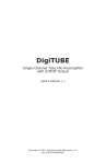
1
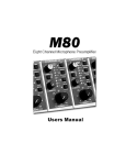
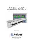
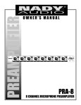
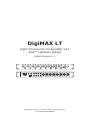
DigiMAX LT
Eight-Channel Mic-Preamplifier with
adat™ Lightpipe Output
USER’S MANUAL 1.0
-20
-10
CLIP
-20
-10
CLIP
PAD
dB
60
115/230 VAC ~
(by internal
jumpers)
dB
60
0
-10
CLIP
dB
-20
CLIP
-20
60
0
dB
CLIP
60
0
dB
-20
60
CLIP
0
dB
60
-10
CLIP
PAD
30
+48V
0
GAIN
dB
60
SAMPLE
RATE
EXT
CLOCK
32k
48k
POWER
+48V
0
GAIN
dB
44.1k
60
GAIN
8
7
6
5
-20
PAD
30
+48V
GAIN
4
-10
PAD
30
+48V
GAIN
3
-10
PAD
30
+48V
WORD CLOCK
POWER
20WATTS
CREATED,
DESIGNED
AND
MANUFACTURED
IN THE USA
-10
PAD
30
GAIN
2
1
-20
+48V
GAIN
1
CLIP
30
+48V
0
GAIN
-10
PAD
30
+48V
0
-20
PAD
30
OUT
IN
7
5
3
CHANNEL 8
CHANNEL 7
CHANNEL 6
CHANNEL 5
CHANNEL 4
CHANNEL 3
CHANNEL 2
CHANNEL 1
MICROPHONE - XLR
LINE INPUT - TRS
MICROPHONE - XLR
LINE INPUT - TRS
MICROPHONE - XLR
LINE INPUT - TRS
MICROPHONE - XLR
LINE INPUT - TRS
MICROPHONE - XLR
LINE INPUT - TRS
MICROPHONE - XLR
LINE INPUT - TRS
MICROPHONE - XLR
LINE INPUT - TRS
MICROPHONE - XLR
LINE INPUT - TRS
1
CHANNEL INSERT POINTS
adat™
optical
interface
DIGITAL
AUDIO
OUTPUT
8
6
4
2
Copyright © 2002, PreSonus Audio Electronics, Inc.
ALL RIGHTS RESERVED
TABLE OF CONTENTS
1
1.1
1.2
Overview.................................................................................. 1
Introduction ............................................................................... 1
Features .................................................................................... 2
2
2.1
2.2
Controls & Connections ............................................................ 3
Front Panel................................................................................. 3
Back Panel ................................................................................. 5
3
3.1
3.2
3.3
3.4
Operations ............................................................................... 6
Dynamic Microphones .................................................................. 6
Phantom Powered Mics ................................................................ 6
Line Level Inputs......................................................................... 6
Application Guide ........................................................................ 6
4
Technicial Specifications .........................................................10
4
PreSonus Limited Warranties ................................................. 12
i
OVERVIEW 1
1.1 INTRODUCTION
Thank you for purchasing the PreSonus DigiMAX LT Eight-Channel Mic-Preamplifier with adat™ Lightpipe Output. This preamp was designed using state of the
art components to deliver crystal clear audio for an indefinite period of time. We
believe the DigiMAX LT to be an exceptional sounding unit and an exceptional
value.
Please contact us at 1-800-750-0323 with your questions or comments regarding this product. PreSonus Audio Electronics, Inc. is committed to constant
product improvement and believes the best way to accomplish this task is by
listening to the experts on our gear, our valued customers. We appreciate the
support you have shown us through the purchase of this product.
Please pay close attention to how you connect your DigiMAX LT to your system.
Improper grounding is the most common cause of noise problems found in
studio or live sound systems. We urge you to scan this manual before hooking
up your DigiMAX LT to familiarize yourself with its features and applications.
Good luck and enjoy your DigiMAX LT!
1
1 OVERVIEW
1.2 FEATURES
Dual Servo Mic Preamps
Each channel of your DigiMAX LT provides ultra low noise and wide gain control
allowing the user to boost a desirable signal without increasing unwanted
background noise.
48V Phantom Power
Each channel of the DigiMAX LT has 48V of phantom power available. When the
phantom power switch is engaged, power is supplied at a constant rate. This
assures optimum performance of your condenser microphone(s) and that it will
be free of distortion associated with insufficient power. This switch is located on
the front panel next to each gain knob.
-20dB Pad
A -20dB pad is available on each channel of the DigiMAX LT for reducing
incoming signal levels. Using this pad can provide a more manageable signal
from high output devices giving the operator greater control over the incoming
signal and a much reduced chance of over-driving the input, thereby avoiding
distortion.
Neutrik™ Combo Connectors
Each channel of the DigiMAX LT has a mic/line connector using the Neutrik™
combo connector. This revolutionary style connector lets you use either 1⁄4” or
XLR connectors in the same input.
Sample Rate Selector
The DigiMAX LT has a switch on the front panel that lets the operator choose
the sample rate. It provides selectable rates of 32k, 44.1k and 48k.
Ext Clock
When the External clock switch is engaged the DigiMAX LT goes into ‘chase’
mode and automatically recognizes which of the three sampling rates is
required for optimum synchronization.
Digital Optical Output
The DigiMAX LT has an adat™ (lightpipe) output that can be used with any commercially available digital optical cable. This cable can supply eight simultaneous
outputs.
2
CONTROLS AND CONNECTIONS 2
2.1 FRONT PANEL
-20
-10
CLIP
-20
-10
CLIP
PAD
dB
60
dB
60
1
-20
CLIP
dB
-20
60
CLIP
dB
-20
60
dB
60
-20
CLIP
60
CLIP
PAD
+48V
0
dB
60
SAMPLE
RATE
EXT
CLOCK
32k
48k
POWER
+48V
0
GAIN
6
-10
30
+48V
dB
-20
PAD
30
GAIN
5
-10
PAD
0
GAIN
4
CLIP
30
+48V
0
GAIN
-10
PAD
30
+48V
0
3
-10
PAD
30
GAIN
2
-10
+48V
0
GAIN
1
CLIP
30
+48V
0
GAIN
-10
PAD
30
+48V
0
-20
PAD
30
dB
44.1k
60
GAIN
7
8
Notice that the front panel is divided into eight preamplifier sections, sample
rate selector with indicators and external clock switch.
+48V
1
2
3
A switch labeled +48V is located next to each gain knob.
This switch may be engaged to provide phantom power for
condensor mics and any other device which may require
phantom power by way of the XLR input. This power is
supplied at a constant rate to allow use of all eight inputs
simultaneously, without any degradation of audio quality.
Pin 1 = GND, Pin 2 = +48V, Pin 3 = +48V
Gain Control
This knob provides 44dB of gain to the processed signal. The amplifier has
inherent gain of 10dB thus delivering a total gain possibility of 54dB.
-20dB Pad
A -20dB pad is available on each channel of the DigiMAX LT for reducing
incoming signal levels. Using this pad can provide a more manageable signal
from high output devices giving the operator greater control over the incoming
signal and a much reduced chance of over-driving the input, thereby avoiding
distortion.
The pad is available only for the XLR input on each channel. The pad does not
work for the line level inputs.
Channel LEDs
The three LEDs found on each channel are provided to serve different functions:
-20dBu - The LED farthest to the left is labeled -20 and serves to monitor
whether or not signal is present at the channel output.
-10dBu - The LED in the middle is labeled -10 and indicates a signal level
of -10dBU
3
CONTROLS & CONNECTIONS 2
Clip - The LED labeled CLIP indicates at a signal level of +22dB. Care should be
taken to avoid using signal levels that cause this LED to become active. Signal
levels that reach or exceed this amount of output will cause undesirable artifacts
(distortion) in the channel output signal that is being indicated by this LED. The
signal level is reduced by rotating the channel’s control counter-clockwise.
Sample Rate Selector
The section at the extreme right of the front panel contains the sample rate
selector switch with LED indicators provided for 32k, 44.1k and 48k. This
section also contains a switch labeled EXT. CLOCK. When this switch is engaged
the operating clock rate of 32k, 44.1, or 48k will be determined by the incoming signal from an external device through the word clock in input on the back
panel of the DigiMAX LT.
4
CONTROLS & CONNECTIONS 2
2.2 BACK PANEL BASIC LAYOUT
115/230 VAC ~
(by internal
jumpers)
WORD CLOCK
POWER
20WATTS
CREATED,
DESIGNED
AND
MANUFACTURED
IN THE USA
OUT
IN
7
5
3
CHANNEL 8
CHANNEL 7
CHANNEL 6
CHANNEL 5
CHANNEL 4
CHANNEL 3
CHANNEL 2
CHANNEL 1
MICROPHONE - XLR
LINE INPUT - TRS
MICROPHONE - XLR
LINE INPUT - TRS
MICROPHONE - XLR
LINE INPUT - TRS
MICROPHONE - XLR
LINE INPUT - TRS
MICROPHONE - XLR
LINE INPUT - TRS
MICROPHONE - XLR
LINE INPUT - TRS
MICROPHONE - XLR
LINE INPUT - TRS
MICROPHONE - XLR
LINE INPUT - TRS
1
CHANNEL INSERT POINTS
adat™
optical
interface
8
6
4
DIGITAL
AUDIO
OUTPUT
2
Digital Optical Output
An adat™ optical output (lightpipe) is provided on the rear panel of the DigiMAX
LT. Eight simultaneous 24bit outputs are possible when using the optical out.
Word Clock Out/In
The word clock output and input are accessed through separate BNC connectors. The internal sample rate can be set to send 32k, 44.1k, or 48k. The
word clock in scans the incoming information and automatically synchs to the
necessary sample rate.
Insert
Each channel of the DigiMAX LT has an insert that sends and returns the signal
from the associated channel. This insert can be very useful for dynamics
processing (such as compressing, limiting, etc.) or for monitoring purposes by
helping in overcoming the time discrepancy that may be encountered in some
digital recording situations. For more detailed instructions on uses and wiring
of the inserts please see the application guide at the end of the manual. This
insert is wired as follows:
Sleeve
Ring
Tip
Tip
Sleeve
Ring
TIP = Send
RING = Return
SLEEVE = GND
5
3 OPERATIONS
3.1 DYNAMIC MICROPHONES
Dynamic microphones are characterized by lower output levels. Hence, more
gain is needed to amplify a dynamic microphone to operating level. Occasionally
it is necessary to add the -20dB pad to the microphone to avoid distortion (e.g.
when recording percussion).
Do not use phantom power when using dynamic microphones.
3.2 PHANTOM POWERED MICROPHONES
Phantom powered microphones such as condenser and some ribbon microphones require external power to preamplify the microphone acoustic pickup.
These microphones typically have much higher output than dynamic microphones. Hence the -20dB pad is almost always necessary when close micing to
avoid clipping the amplifier.
3.3 LINE LEVEL INPUTS
The 1⁄4” inputs on the DigiMAX LT are designed for use with line level or low
impedance inputs not instrument level inputs. These inputs will work for line
level devices such as keyboards, samplers, drum machines, CD players, etc.
3.4 APPLICATION GUIDE
Outboard Dynamics Processing Example
The DigiMAX LT has an insert on every channel that allows you to insert your
own dynamics processor, such as a compressor, EQ, limiter, or etc. To do this,
all you need is your dynamics processor and a TRS insert cable. This cable is Yshaped, has a single TRS 1⁄4” jack on one end and two 1⁄4” TS jacks on the other
end. The single end will look like a stereo 1⁄4” connector jack. This end of the
cable plugs into the insert jack on the back of the DigiMAX LT. The other ends
of the cable plug into the input and output of the outboard unit. If the outboard
unit does not work immediately, you may want to try swapping the jacks that
are plugged into the input and output of the outboard unit.
Insert Jacks As Analog Outputs Example 1
You may have noticed by now that the DigiMAX LT does
not have a standard analog output. In the event that you
want to have analog outputs as well as the lightpipe output,
you can use the inserts as analog outputs. To do this, all
you need is a 1⁄4” TS cable. Plug the cable in until you feel
6
OPERATIONS 3
it ‘click’ once. The cable will appear to be ‘half plugged in’. Using the insert in
this fashion will not break the signal chain and will allow the lightpipe output to
function correctly.
Insert Jack As Analog Outputs Example 2
In the event that you do not need the lightpipe output, you can use the inserts
as analog outputs. To do this, all you need is a TRS insert cable. This cable is
Y-shaped, has a single TRS 1⁄4” jack on one end and two 1⁄4” TS jacks on the
other end. The single end will look like a stereo 1⁄4” connector. This end of the
cable plugs into the insert jack above the input on the back of the DigiMAX LT.
You would use the SEND end of the cable as the output cable.
By using the insert as an analog output with an insert cable, you will not be
able to pass a signal through to the adat™ (lightpipe) output. The reason for
this is that a signal is sent to a piece of outboard gear from the insert jack and
then returned to the insert after being processed. So, in other words you are
breaking the signal chain by using the send and not the return.
Using The DigiMAX LT As A Front End For Digital Recording Systems
The DigiMAX LT is the perfect front end for a digital recording system. The preamps on the unit allow you to boost the signal going to your recorder without
adding extra, unwanted, noise. All digital recorders require that word clock be
transmitted with a digital audio signal to ensure sample accuracy and synchronization. Word clock scans incoming information and automatically synchs
to the necessary sample rate. In other words, word clock ensures that the
recorder and the sending device (in this case the DigiMAX LT) send and receive
digital audio at the same rate. If there is no word clock synch then you will hear
pops, clicks, or weird digital dropout noise. Word clock can either be transmitted through the lightpipe cable (fiber-optic) or by BNC cable. If the DigiMAX
LT is the master (sending word clock out to the recorder), then there are two
possible connection scenarios. Both cases require that the EXT CLOCK button
on the front of the unit be depressed (not pushed in) and that the appropriate
sample rate be selected by using the SAMPLE RATE button on the front of the
unit. The first case in which the DigiMAX LT is the master would require that the
word clock output of the DigiMAX LT be connected to the word clock input of the
recorder by BNC cable. The second case in which the DigiMAX LT is the master
would require that the recorder receive word clock from the adat™ lightpipe
fiber-optic cable. This second scenario requires that the digital recorder be set
to receive word clock via lightpipe. This is often done by either hitting a button
7
3 OPERATIONS
on the recorder that says external clock or by setting a drop down menu option
to receive sync from an external source or lightpipe.
In the event that you want to slave the DigiMAX LT to another device you would
need to do two things. First, press the EXT CLOCK button on the front of the
unit. Second, you would hook a BNC cable from the word clock output of the
sending device to the word clock input on the back of the DigiMAX LT.
Bypassing The DigiMAX LT Preamps
The DigiMAX LT can be used as an analog to digital converter. The setup for this
application requires a TRS insert cable. This cable is Y-shaped, has a single TRS
1⁄4” jack on one end and two 1⁄4” TS jacks on the other end. The single end will
look like a stereo 1⁄4” connector. This end of the cable plugs into the insert jack
on the back of the DigiMAX LT. You would use the return end of the cable as the
input cable. By plugging a device into the return cable, you would be entering
the signal chain after the preamp. This would allow you to digitize a signal (such
as a keyboard or CD player) without passing through the DigiMAX LT preamp.
The DigiMAX LT is not designed for direct use with record players - An RIAA
(Recording Industry of America Association) phono preamplifier would have to
be inserted in between the record player and the DigiMAX LT. If this RIAA phono
preamplifier is not used then you would not hear an accurate representation of
the recording.
The DigiMAX LT is designed for use with line level or low impedance inputs NOT
instrument level inputs - The 1/4” inputs on the DigiMAX LT are lower impedance than our typical instrument inputs. In other words, if you were to plug a
guitar into the DigiMAX LT directly, you probably wouldnít hear anything. Use of
an impedance matching direct box will provide the correct impedance for instruments (ex: guitar, bass, etc.). However, you can plug microphones (dynamic or
condenser), keyboards, samplers, drum machines, CD Players and etc. into the
DIGIMAX LT.
8
OPERATIONS 3
9
4 TECHNICAL SPECIFICATIONS
Number of Channels ................................................................................ 8
Input
Input Impedance, XLR Input ............................................................. 1.3k Ω
Input Impedance, Line Level Input...................................................... 10k Ω
Connectors ...................................................................... Neutrik™ Combo
Panel Controls
Gain .................................................................................... 0dB to +40dB
Pad................................................................................................. -20dB
Phantom Power ................................................................................. +48V
Meters
Signal Present LED ..........................................................................-20dBu
Signal Level LED..............................................................................-10dBu
Clip LED .......................................................................................+22dBu
Output
adat™ Lightpipe Digital Optical .............................................................24bit
Insert (TRS)
Send (Unbalanced) ....................................................................... 51 Ohms
Return (Unbalanced)..................................................................... 10 Ohms
Digital
Sampling Rates ........................................................ 32kHz, 44.1kHz, 48kHz
Performance
Headroom .....................................................................................+22dBu
Freq. Response ...................................................... 20Hz - 50kHz (+/- .5dB)
THD + Noise (Unweighted) ............................................................<0.009%
Noise Floor .....................................................................................-94dBu
Signal to Noise................................................................................ >98dB
Analog Dynamic Range....................................................................>120dB
Power Supply Rejection .................................................................... >98dB
Amplifier Type ............................................................................Dual Servo
Power Supply
Type ................................................................................... Linear, Internal
10
TECHNICAL SPECIFICATIONS 4
Input ........................................... 100/120/220/240VAC (Factory Configured)
Power ..........................................................................................80 Watts
Physical
Size ..............................................................................................1U Rack
Dimensions........................................................................ 19” X 1.75” X 9”
Weight ........................................................................................... 15 lbs.
Chassis ............................................................................................. Steel
Panel ......................................................................................... Aluminum
As a commitment to constant improvement, PreSonus reserves the right to change any
specification stated herein at any time in the future without prior notification.
11
5 PRESONUS LIMITED WARRANTY
IN THE UNITED STATES
PreSonus Audio Electronics Inc. warrants this product to be free of defects in material
and workmanship for a period of one year from the date of original retail purchase.
This warranty is enforceable only by the original retail purchaser. To be protected by this
warranty, the purchaser must complete and return the enclosed warranty card within 14
days of purchase. During the warranty period PreSonus shall, at its sole and absolute
option, to either repair or replace, free of charge, any product that proves to be defective
on inspection by PreSonus or its authorized service representative. To obtain warranty
service, the purchaser must first call or write PreSonus at the address and telephone
number printed below to obtain a Return Authorization Number and instructions of where
to return the unit for service. All inquiries must be accompanied by a description of
the problem. All authorized returns must be sent to the PreSonus repair facility postage
prepaid, insured and properly packaged. PreSonus reserves the right to update any unit
returned for repair. PreSonus reserves the right to change or improve the design of the
product at any time without prior notice. This warranty does not cover claims for damage
due to abuse, neglect, alteration or attempted repair by unauthorized personnel, and is
limited to failures arising during normal use that are due to defects in material or workmanship in the product. Any implied warranties, including implied warranties of merchantability
and fitness for a particular purpose, are limited in duration to the length of this limited
warranty. Some states do not allow limitations on how long an implied warranty lasts,
so the above limitation may not apply to you. In no event will PreSonus be liable for
incidental, consequential or other damages resulting from the breach of any express or
implied warranty, including, among other things, damage to property, damage based on
inconvenience or on loss of use of the product, and, to the extent permitted by law,
damages for personal injury. Some states do not allow the exclusion of limitation of
incidental or consequential damages, so the above limitation or exclusion may not apply
to you. This warranty gives you specific legal rights, and you may also have other rights,
which vary form state to state. This warranty only applies to products sold and used in
the United States of America. For warranty information in all other countries please refer
to your local distributor.
PreSonus Audio Electronics, Inc.
7257 Florida Blvd.
Baton Rouge, LA 70806
(225) 216-7887
Copyright © 2002, PreSonus Audio Electronics, Incorporated. All rights reserved.
12
PRESONUS LIMITED WARRANTY 5
OUTSIDE OF THE UNITED STATES
PreSonus Audio Electronics products are warranted only in the country where originally
purchased, through the authorized PreSonus distributor in the country of original purchase,
against defects in material and workmanship. The specific period of this limited warranty
shall be that which is described to the original retail purchaser by the authorized PreSonus
dealer or distributor at the time of purchase. PreSonus does not, however, warrant its
products against any and all defects: 1) arising Out of materials or workmanship not
provided or furnished by PreSonus, or 2) resulting from abnormal use of the product or use
in violation of instructions, or 3) in products repaired or serviced by other than authorized
PreSonus repair facilities, or 4) in products with removed or defaced serial numbers, or 5)
in components or parts or products expressly warranted by another manufacturer. PreSonus agrees, through the applicable authorized distributor in the country of original retail
purchase, to repair or replace defects covered by this limited warranty with parts or products of original or improved design, at its option in each respect, if the defective product
is shipped prior to the end of the warranty period to the designated authorized PreSonus
warranty repair facility in the country where purchased, or to the PreSonus factory in the
U.S., in the original packaging or a replacement supplied by PreSonus, with all transportation cost and full insurance paid each way by the purchaser or owner. All remedies and the
measure of damages are limited to the above services. It is possible that economic loss or
injury to person or property may result from the failure of the product; However, even if
PreSonus has been advised of this possibility, this limited warranty does not cover any such
consequential or incidental damages. Some states or countries do not allow the limitations
or exclusion of incidental or consequential damages, so the above limitation may not apply
to you. Any and all warranties, express or implied, arising by law, course of dealing, course
of performance, usage of trade, or otherwise, including but not limited to implied warranties of merchantability and fitness for a particular purpose, are limited to a period of one
year from either the date of original retail purchase or, in the event no proof of purchase
date is available, the date of manufacture. Some states or countries do not allow limitations
on how long an implied warranty last, so the above limitations may not apply to you. This
limited warranty gives you specific legal rights, and you may also have other rights which
vary from state to state, country to country.
PreSonus Audio Electronics, Inc.
7257 Florida St.
Baton Rouge, LA 70806
(225) 216-7887
Copyright © 2002, PreSonus Audio Electronics, Incorporated. All rights reserved.
13