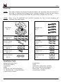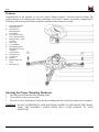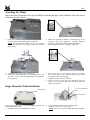
1
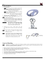
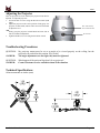
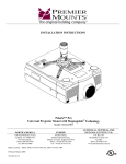
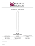
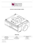
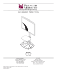
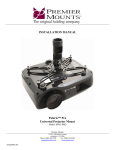
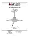
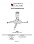
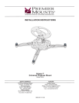
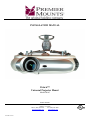
INSTALLATION MANUAL
Polaris™
Universal Projector Mount
Model: MAG
Premier Mounts
3130 E. Miraloma Avenue
Anaheim, CA 92806
Phone: (800) 368-9700
Fax: (800) 832-4888
[email protected]
www.mounts.com
9530-001-011-07
MAG
Table of Contents
Parts List .............................................................................................................................................................- 3 Installation Tools ................................................................................................................................................- 3 Features ...............................................................................................................................................................- 4 Selecting the Proper Mounting Hardware...........................................................................................................- 4 Attaching the Mount ...........................................................................................................................................- 5 Single Mounting Point Installation .....................................................................................................................- 5 Ceiling Installation..............................................................................................................................................- 6 Concrete Mounting .............................................................................................................................................- 6 Adjusting the Projector .......................................................................................................................................- 7 Troubleshooting Procedures ...............................................................................................................................- 7 Technical Specifications .....................................................................................................................................- 7 Warranty .............................................................................................................................................................- 8 Warning Statements ............................................................................................................................................- 8 -
Page - 2 -
Installation Manual
MAG
Parts List
NOTE:
This mount is shipped with all proper installation hardware and components. Make sure that none of
these parts are missing and/or damaged before beginning installation. If there are parts missing
and/or damaged, please stop the installation and contact Premier Mounts (800-368-9700).
NOTE:
Please review all WARNING and CAUTION statements (see Page 8) before beginning the
installation of the MAG Mount.
MAG Mount
(Qty 1)
M6 x 12mm
Security Screw
(Qty 8)
#14 X 2” Wood
Screw (Qty 3)
M4 x 12mm
Security Screw
(Qty 6)
¼ – 20 x 5/16”
Security Screw
(Qty 1)
M4 Star Washers
(Qty 2)
Mounting Legs
(Qty 4)
M3 Flat Washers
(Qty 4)
M5 x 12mm
Security Screw
(Qty 4)
M3 x 16mm
Security Screw
(Qty 4)
M2.5 x 8mm
Security Screw
(Qty 4)
Plastic Barrel Caps
(Qty 4)
Installation Tools
Phillips Head Screw Driver
Soft Material/ Blanket
Tape Measure
Ladder
M3 Security Allen Wrench (Supplied)
1/8” Wood Drill Bit – Ceiling Installation
(Commercially Available)
Installation Manual
Portable Drill
Pencil
Stud Finder (Commercially Available)
M5 Security Allen Wrench (Supplied)
Masonry Bit – Concrete Installation
(Commercially Available)
Page - 3 -
MAG
Features
Congratulations on the purchase of your new Premier Mounts Polaris™ Universal Projector Mount. The
projector mount can be configured for ceiling installations. The Polaris™ features our exclusive MagnaGuide™
Technology which assists the installer for quicker installation times and peace of mind.
A
B
C
D
E
F
G
H
I
J
K
L
M
N
O
Single Wooden Stud
Mounting Points
Solid Structure
Mounting Points
Ceiling Plate
M4 x 12mm Security
Screw and Star Washer
MagnaGuide™ - Upper
Assembly
Barrel Cap
Leveling Barrel
Mounting Hardware
MagnaGuide™-Lower
Assembly
Projector Plate
M6 Square Nut
Locking Tab
Magnets
Radial Glide™ Set
Screw
Mounting Leg
Selecting the Proper Mounting Hardware
1.
2.
3.
Invert the projector and locate the mounting points.
Test each size of the screws provided.
The correct screws should thread easily into the mounting point and not pull out when pressure is applied.
WARNING: DO NOT OVERTIGHTEN YOUR MOUNTING SCREWS TO THE PROJECTOR CHASIS.
USING THE INCORRECT SCREW DEPTH MAY CAUSE DAMAGE TO YOUR
PROJECTOR.
Page - 4 -
Installation Manual
MAG
Attaching the Mount
Unpack the MAG Mount and review any WARNING statements that apply to the installation. Select the desired
location for the MAG Mount.
1.
Locate the mounting points on the bottom of the projector
(see arrows above for mounting point recognition).
NOTE: Projector mounting points will vary. The projector
used in this manual is an example, and may not match
yours exactly.
2.
Attach the appropriate number of mounting legs to the
projector using the appropriate mounting hardware
(see Page 4, Selecting the Proper Mounting Hardware).
3. Do not tighten these screws completely at this time.
4.
5.
Align the projector plate to the mounting legs.
Position the legs accordingly for best configuration. You
may raise or lower each leg independently by turning the
leveling barrels.
6.
7.
8.
Secure the legs to the projector plate by screwing
M6 x 12mm security screws into the M6 square nut (do not
overtighten) on the mounting legs.
Tighten all security screws at this time.
Once the security screws have been tightened, place the
plastic cap over each leveling barrel and firmly push the
plastic cap into place.
Single Mounting Point Installation
¼-20 x 5/16” Mounting
Screw
Mounting Point
Standard Hole
If your projector has a ¼-20 x 5/16” mounting point, please refer
to the following three steps:
1. Determine where the mounting point is located.
Installation Manual
2.
3.
Place the projector plate over the mounting point.
Insert the ¼-20 x 5/16” security screw.
NOTE: This screw will use a standard hole when mounting.
Page - 5 -
MAG
Ceiling Installation
1. Mounting Surfaces
NOTE: Use a 1/8” drill bit to pre-drill the mounting holes
before securing the wood screws (supplied).
Wood studs: Where denoted with the letter ‘A’, mark these
locations for wood stud installation.
NOTE: Use a masonry bit to pre-drill the mounting
holes in the concrete surface.
Concrete surface: Where denoted with the letter ‘B’, mark
these locations for concrete installation.
2. Use two (2) #14 x 2” wood screws (supplied) to attach the
ceiling plate to the wooden ceiling stud.
NOTE: For extra security, attach a third wood screw to the
middle mounting point (A).
3. Slowly raise the projector toward the upper assembly. Once
the projector is close to the upper assembly, MagnaGuide™
Technology will pull the lower assembly into the upper
assembly and the locking tab will engage.
WARNING:
THE MAGNETS ARE USED FOR GUIDING
THE UNIT ONLY! PLEASE MAKE SURE
THE TWO (2) M4 X 12MM SCREWS ARE
USED TO SECURE THE PROJECTOR.
4.
Attach the two (2) M4 x 12mm security screws and
star washers that are located on each side of the locking
tab.
NOTE: Do not release your hold on the projector until the
upper and lower assemblies are engaged and the
locking tab is in place.
NOTE:
If you choose to use the center mounting point for
added security, detach the lower assembly from the
ceiling plate by removing the two (2) M6 x 12mm
security screws, drive the wood screw in place and
reattach the lower assembly and security screws.
M6 x 12mm
Security Screw
M5 Allen
Wrench
Concrete Mounting
NOTE:
1.
2.
3.
4.
5.
6.
7.
8.
The MAG can be mounted to a ceiling with a minimum 6” thickness. Concrete wedge anchors must be used for concrete
installation. It is recommended that ¼” wedge anchors be used. A masonry bit must be used to drill the pilot hole. These
items can be purchased at your local hardware store.
Begin by placing the ceiling plate into position against the ceiling, keeping it level.
Mark off four holes to be used for securing the mount and place the ceiling plate aside.
Next, drill holes using the appropriate masonry bit for your anchor.
Insert a concrete anchor into each hole.
If necessary, a hammer can be used to lightly tap each anchor into place so that they are flush with the ceiling.
Once all of the anchors are in place, move the ceiling plate back into position.
Attach the nut onto the threaded shaft that is protruding from the ceiling.
Do not tighten until all nuts are in place.
Page - 6 -
Installation Manual
MAG
Adjusting the Projector
After the projector has been installed, the projector must then be
adjusted. To adjust the projector:
1. Loosen the M5 set screw using the M5 Allen wrench (both
sides).
2. Adjust the projector to the correct position. Firmly grasp the
projector in both hands, and tilt either forward or backward
to adjust the level.
-ORFirmly grasp the projector in both hands and rotate side to
side for orientation adjustment.
3. Tighten both M5 set screws using the M5 Allen wrench.
M4 x 12mm Security
Screw and Star Washer
M5 Set Screw
Troubleshooting Procedures
QUESTION:
ANSWER:
My projector mount must be set at an angle to be viewed properly on the ceiling, but the
projector will not hold at this position. Why is this?
The angle adjustments are not tight; they must be tightened.
QUESTION:
ANSWER:
What happens if the universal legs don’t fit my projector?
Contact Customer Service and advise them of the situation.
Technical Specifications
All measurements are inches (mm).
Installation Manual
Page - 7 -
MAG
Warranty
Limited Lifetime Warranty
All Premier Mounts products carry a limited lifetime warranty from ship date against defects in materials and workmanship. Premier Mounts is not
liable for improper installation that results in damage to mounts, adapters, display equipment or personal injury. Any modification to the existing
mount will void the manufacturers’ warranty.
DISCLAIMER OF WARRANTY.
THE FOREGOING WARRANTY IS IN LIEU OF ALL OTHER WARRANTIES, EXPRESS OR IMPLIED, INCLUDING BUT NOT
LIMITED TO THE IMPLIED WARRANTIES OF MERCHANTABILITY AND FITNESS FOR A PARTICULAR PURPOSE.
Warning Statements
WARNING:
PREMIER MOUNTS DOES NOT WARRANT AGAINST DAMAGE CAUSED BY THE USE OF ANY PREMIER MOUNTS
PRODUCT FOR PURPOSES OTHER THAN THOSE FOR WHICH IT WAS DESIGNED OR DAMAGE CAUSED BY
UNAUTHORIZED ATTACHMENTS OR MODIFICATIONS, AND IS NOT RESPONSIBLE FOR ANY DAMAGES, CLAIMS,
DEMANDS, SUITS, ACTIONS OR CAUSES OF ACTION OF WHATEVER KIND RESULTING FROM, ARISING OUT OF
OR IN ANY MANNER RELATING TO ANY SUCH USE, ATTACHMENTS OR MODIFICATIONS.
WARNING:
THE CEILING STRUCTURE MUST BE CAPABLE OF SUPPORTING 25LBS.. IF NOT, THE CEILING STRUCTURE MUST
BE REINFORCED. PROPER INSTALLATION PROCEDURE BY A QUALIFIED SERVICE TECHNICIAN, AS OUTLINED IN
THE INSTALLATION INSTRUCTIONS, MUST BE ADHERED TO. FAILURE TO DO SO COULD RESULT IN SERIOUS
PERSONAL INJURY, OR EVEN DEATH.
WARNING:
SAFETY MEASURES MUST BE PRACTICED AT ALL TIMES DURING THE INSTALLATION OF THIS PRODUCT. USE
PROPER SAFETY GEAR AND TOOLS FOR THE INSTALLATION PROCEDURE TO PREVENT PERSONAL INJURY.
WARNING:
PRIOR TO THE INSTALLATION OF THIS PRODUCT, THE INSTALLATION INSTRUCTIONS SHOULD BE READ AND
COMPLETELY UNDERSTOOD. THE INSTALLATION INSTRUCTIONS MUST BE READ TO PREVENT PERSONAL
INJURY AND PROPERTY DAMAGE. KEEP THESE INSTALLATION INSTRUCTIONS IN AN EASILY ACCESSIBLE
LOCATION FOR FUTURE REFERENCE.
Indicates that the power plug is to be disconnected from the
power outlet.
Contact Premier Mounts with any questions –
Customer Service – (800) 368-9700
Technical Support – [email protected]
Safety precautions must be taken at all times.
Warning and Caution statements.
Do not install on a structure that is prone to vibration, movement or chance of impact. Failure to do so could result in damage to the projector
and/or damage to the mounting surface.
Do not install near heater, fireplace, direct sunlight, air conditioning or any other source of direct heat energy. Failure to do so may result in
damage to the projector and could increase the risk of fire.
A qualified person should perform the installation procedure. Injury and/or damage can result from dropping or mishandling the projector
NORTH AMERICA
3130 East Miraloma Avenue
Anaheim, CA 92806 USA
USA and Canada –
Phone: 800-368-9700
Fax: 800-832-4888
EUROPE
Swallow House,
Shilton Industrial Estate,
Shilton, Coventry, England CV79JY
Phone: +44 (0) 2476 614700
Fax: +44 (0) 2476 614710
AUSTRALIA, NEW ZEALAND, OCEANIA
(DISTRIBUTOR)
P.O. Box 295
Mordialloc Victoria 3195
Australia
Phone: 039586 6330
www.premiermounts.com.au
Other Locations – Phone: (001)-714-632-7100; Fax: (001)-714-632-1044
©Premier Mounts 2007
9530-001-011-07
Page - 8 -
Installation Manual