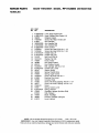
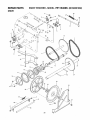
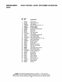
1
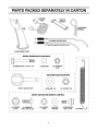
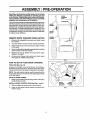
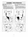
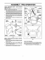
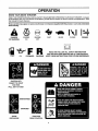
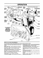
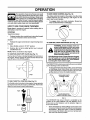
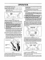
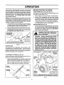
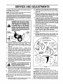
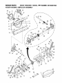
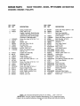
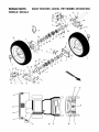
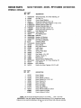
IMPORTANT MANUAL
OWNER'S
Do Not Throw Away
MANUAL
MODEL NUMBER:
WARNING:
96192001902
SNOW THROWER
Always
III
Wear Eye Protection
Read
the Owner's
and
follow all Warnings
and Safety
Instructions.
Failure to do so
can result
During
..................
Manual
Operation
in serious
injury.
416804 09.20.07 SR
Printed in U.S.A.
I
IMPORTANT
Safe Operation Practices for Walk-Behind
Snow Throwers
This snow thrower is capable of amputating hands and feet and throwing objects.
Failure to observe the following safety instructions could result in serious injury.
i
&
i
llnll,
WARNING: Always disconnect spark
plug wire and place it where it cannot
contact plug in order to prevent accidental starting when setting up, transporting, adjusting or making repairs.
i i ii1,111
i
&
WARNING: This snow thrower is for
use on sidewalks, driveways and other
ground level surfaces. Caution should
be exercised while using on sloping surfaces.
Do not use snow thrower on
surfaces above ground level such as
roofs of residences, garages, porches
or other such structures or buildings.
I
Keep the area of operation
ticularly small children.
4.
Exercise caution to avoid slipping or falling, especially
when operating the snow thrower in reverse.
I
II
I
I
I
I
II
II
IIII
I II
IIII
I
IIIIII
III I
II IIIIII II
CAUTION: Muffler and other engine
parts become extremely
hot during
operation and remain hot after engine
has stopped. To avoid severe burns on
contact, stay away from these areas.
tank or container opening at all times, until refueling is complete. Do not use a nozzle lock-open
device.
(g) Replace gasoline cap securely and wipe up spilled
fuel.
(h) If fuel is spilled on clothing,
mediately.
par-
Preparation
1.
Thoroughly inspect the area where the equipment is
to be used and remove all doormats, sleds, boards,
wires, and other foreign objects.
2.
Disengage all clutches and shift into neutral
starting the engine (motor).
3.
Do not operate the equipment withoutwearing adequate
winter garments. Avoid loose fitting clothing that can
get caught in moving parts. Wear footwear that will
improve footing on slippery surfaces.
.
(d) Never fill containers inside a vehicle or on a truck
or trailer bed with a plastic liner. Always place
containers on the ground, away from your vehicle,
before fitiing.
(e) When practical, remove gas-powered equipment
from the truck or trailer and refuel it on the ground.
If this is not possible, then refuel such equipment
on a trailer with a portable container, rather than
from a gasoline dispensernozzle.
im-
Use extension cords and receptacles as specified by
the manufacturer for all units with electric drive motors
or electric starting motors.
7.
Never attempt to make any adjustments while the
engine (motor) is running (except when specifically
recommended by manufacturer).
8.
Always wear safety glasses or eye shields during operation or while performing an adjustment or repair to
protect eyes from foreign objects that may be thrown
from the machine.
Operation
1.
Do not put hands or feet near or under rotating parts.
Keep clear of the discharge opening at all times.
2.
Exercise extreme caution when operating on or crossing gravel drives, walks, or roads. Stay alert for hidden
hazards or traffic.
3.
After striking a foreign object, stop the engine (motor),
remove the wire from the spark plug, disconnect the
cord on electric motors, thoroughly inspect the snow
thrower for any damage, and repair the damage before
restarting and operating the snow thrower.
4.
If the unit should start to vibrate abnormally, stop the
engine (motor) and check immediately for the cause.
Vibration is generally a warning of trouble.
5.
Stop the engine (motor) whenever you leave the operating position, before unclogging the collector!impeller
housing or discharge chute, and when making any
repairs, adjustments or inspections.
engine or hot en-
(c) Fill fuel tank outdoors with extreme care. Never fill
fuel tank indoors.
clothing
Adjust the collector housing height to clear gravel or
crushed rock surface.
before
(a) Use an approved fuel container.
change
6.
Handle fuel with care; it is highly flammable
(b) Never add fuel to a running
gine.
I
(f) Keep the nozzle in contact with the rim of the fuel
Never allow chiIdren to operate the equipment. Never
allow adults to operate the equipment without proper
instruction.
3.
4.
n,ll
II
Training
1. Read, understand and follow all instructions on the
machine and in the manual(s) before operating this
unit. Be thoroughly familiar with the controls and the
proper use of the equipment. Know how to stop the
unit and disengage the controls quickly.
clear of all persons,
null ,I,l,,,m,,,,H
WARNING: Engine exhaust, some of
its constituents,
and certain vehicle
components
contain or emit chemicals known to the State of California
to cause cancer and birth defects or
other reproductive harm.
I
2.
iHll
WARNING:
Snow throwers
have exposed rotating parts, which can cause
severe injury from contact, or from material thrown from the discharge chute.
Keep the area of operation clear of all
persons, small children and pets at all
times including startup.
Look for this symbol to point out important safety precautions. It means
CAUTIONIH BECOMEALERT!H YOUR
SAFETY IS INVOLVED.
6.
7.
,
9.
When cleaning, repairingor inspectingthe snowthrower,
stop the engine and make certain the collector/impeller and all moving parts have stopped. Disconnect
the spark plug wire and keep the wire away from the
plug to prevent someone from accidentally starting the
engine.
Do not run the engine indoors, except when starting
the engine and for transporting the snow thrower in or
out of the building. Open the outside doors; exhaust
fumes are dangerous.
16. Never touch a hot engine or muffler.
Clearing a Clogged Discharge Chute
Hand contactwiththe rotatingimpellerinsidethe discharge
chute isthe most common cause of injury associated with
snow throwers. Never use your hand to clean out the discharge chute. To clear the chute:
1. SHUT THE ENGINE OFF!
2. Wait 10 seconds to be sure the impeller blades have
stopped rotating.
Exercise extreme caution when operating on slopes.
Never operate the snowthrower without proper guards,
and other safety protective devices in place and working.
3. Always use a clean-out tool, not your hands.
Maintenance
10. Never direct the discharge toward people or areas
where property damage can occur, Keep children and
others away.
11. Do not overload the machine capacity by attempting
to clear snow at too fast a rate.
Check shear bolts and other boltsat frequent intervals
for propertightnessto be sure the equipmentis in safe
workingcondition.
2. Never store the machine with fue! in the fuel tank
inside a buildingwhere ignitionsources are present
such as hot water heaters, space heaters, or clothes
dryers. Allow the engine to cool before storingin any
enclosure.
12. Never operate the machine at high transport speeds
on slippery surfaces. Look behind and use care when
operating in reverse.
13. Disengage power to the collector/impeller when snow
thrower is transported or not in use.
14. Use only attachments and accessories approved by
the manufacturer of the snow thrower (such as wheel
weights, counterweights, or cabs).
15. Never operatethe snow thrower without good visibility
or light. Always be sure of your footing, and keep a firm
hold on the handles. Walk; never run,
IIIIHHIH I"ll"llll"l I I II
CONGRATULATIONS on your purchase of a new snow
thrower. It has been designed, engineered and manufactured
manGe.
to give best possible dependability
Should you experience any
remedy, please contact your
center. We have competent,
the proper tools to service or
and perfor-
problem you cannot easily
nearest authorized service
well-trained technicians and
repair this unit.
Please read and retain this manual. The instructions will
enable you to assemble and maintain your snow thrower
properly. Always observe the "SAFETY RULES".
SERIAL NUMBER:
and Storage
t.
3.
Always referto operator's manual for important details
if the snow thrower is to be stored for an extended
period.
4.
Maintain or replace safety and instruction labels, as
necessary,
5.
Run the machine a few minutes after throwing snow
to prevent freeze-up of the collector/impeller.
I
PRODUCT
SPECIFICATIONS
Gasoline Capacity 4.0 Quarts (4,54 Liters)
and Type:
Unleaded Regular only
Oil Type
API SG-SL):
SAE 5W-30 or 10W-30
(0° to +40°F)
SAE 0W-30 (below 0°F)
Oil Capacity:
26 Ounces (0,74 Liters)
Spark Plug
Gap:
Champion RJ19LM
0.030" (0,072 mm)
DATE OF PURCHASE:
THE MODELAND SERIAL NUMBERSWILL BE FOUND
ON A DECAL A-t-]-ACH ED TO THE REAR OF THE SNOW
THROWER HOUSING.
YOU SHOULD RECORD BOTH SERIAL NUMBERAND
DATE OF PURCHASE AND KEEP IN A SAFE PLACE
FOR FUTURE REFERENCE.
CUSTOMER
•
•
•
RESPONSIBILITIES
Read and observe the safety rules.
Follow a regular schedule in maintaining, caring for
and using your snow thrower.
Follow the instructions under "Maintenance" and "Storage" sections of this owner's manual,
TABLE OF CONTENTS
SAFETY RULES ........................................................
2-3
PRODUCT SPECIFICATIONS ......................................
3
CUSTOMER RESPONSIBILITIES
................................
3
ASSEMBLY / PRE-OPERATION
...............................
5-7
OPERATION ............................................................
8-13
MAINTENANCE .....................................................
14-15
MAINTENANCE SCHEDULE ..................................... 14
SERVICE AND ADJUSTMENTS ........................... 16-18
STO RAGE ................................................................... 18
TROUBLESHOOTING ................................................ 19
REPAIR PARTS ..................................................... 20-31
WARRANTY ................................................................ 32
(1) POWER
(3) RETAINER
SPRINGS
(1) AUGER CONTROL ROD
_--
(1) TRACTION DRIVE CONTROL ROD \_\
(1) DISCHARGE CHUTE
I
EXTRA
1
SHEAR
BOLTS
AND
NUTS
t
I
I
I
I
I
I
f
I
I
J
t
I
I
I
I
I
!
l
I
1
O
J
(2) SHEAR BOLTS 1/4-20 x 1-3f4
(2) SPACERS
(2) LOCKNUTS
114-20
I
I
L
I
ROTATOR
HEAD
MOUNTING
I
I
SAFETY IGNITION KEY
CHUTE
I
(1) WASHER 3/8
DEFLECTOR
REMOTE
(1) LOCKNUT 318
I
I
J
I
CONTROL
I
l
I
I
(1) LOCKNUT
5/16-18
(1) CARRIAGE
BOLT 5/16-18 x 5/8
(1) LOCKNUT
1/4=20
(1)NYLON
WASHER
(1)SHOULDER
BOLT 1_-20
(1) SPRING
I
I
4
ASSEMBLY / PRE-OPERATION
Read these instructions and this manual in its entirety
before you attempt to assemble or operate your new
snow thrower. Reading the entire manual will familiarize you with the unit, which will assist you in assembly,
operation and maintenance of the product.
SPEED
CONTROL
PLASTIC TIE
"Yournew snow thrower hasbeen assembled at the factory
with the exception of those parts left unassembled for shipping purposes. All parts such as nuts, washers, bolts, etc.,
necessary to complete the assembly have been placed in
the parts bag, To ensure safe and proper operation of your
snow thrower, all parts and hardware you assemble must
be tightened securely, Use the correct tools as necessary
to ensure proper tightness.
REMOVE SNOW THROWER
UPPER
HANDLE
HANDLE
KNOB
LOWER
HANDLE
FROM CARTON
1.
Remove all accessible loose parts and parts boxes
from carton.
2.
Cut down all four corners of carton and lay panels flat.
3.
Remove the two (2) screws securing the auger housing
to the pallet.
4.
Remove all packing materials except plastic tie holding
speed control rod to lower handle.
5.
Remove the two (2) plastic ties securing
handle to the pallet.
6.
Remove snow thrower from carton and check carton
thoroughly for additional loose parts.
the upper
FIG. I
HOW TO SET UP YOUR SNOW THROWER
SPEED CONTROLROD
TOOL BOX (See Fig, 10)
RETAINER
SPRING
A toolbox is provided on your snow thrower. The toolbox is
located on top of the belt cover. Store the extra shear bolts,
nuts and multi-wrench provided in parts bag in the toolbox.
NOTE: The multi-wrench may be used for assembly of the
chute rotator head to snowthrower and making adjustments
to the skid plates.
UNFOLD UPPER HANDLE
1.
Raise upper handleto the operating position and tighten
handle knobs securely.
SPEED
CONTROL
BRACKET
INSTALL SPEED CONTROL ROD (See Figs. 1 and 2)
1, Remove plastic tie securing rod to lower handle,
2, Insert rod into speed control bracket and secure with
retainer spring.
SPEED
CONTROL
LEVER
FIG. 2
5
ASSEMBLY / PRE-OPERATION
|lHmlllllnUl
,n,,,,,im,,ll,lll,ll inl
nlnll
n I
INSTALL TRACTION DRIVE CONTROL ROD
(See Figs. 3 and 4)
The tractiondrive controlrodhas the long loop on the end
of the spring as shown.
1. Slide rubber sleeve up rodand hookend of springinto
pivot bracket with loop opening down as shown.
2. Withtop end ofrod positionedunder leftside of control
panel, push roddownand inserttopend of rodintohole
in drive controlbracket. Secure with retainer spring.
n
i
I
ii I
I
I
INSTALL AUGER CONTROL ROD (See Figs. 5 and 6)
The auger controlrod has the short loop on the end of the
springas shown.
1. Slide rubbersleeve up rodand hookend of springinto
controlarm with loop opening up as shown.
2. With top end of rod positioned under right side of
controlpanel, pushdown on rod and insertend of rod
intohole in augercontrolbracket. Secure with retainer
spring.
DRIVE
CONTROL ROD
AUGER
CONTROL
ARM
=_...
BRACKET
FIG. 3
DRIVE
FIG. 5
RETAINER
SPRING
AUGER
CONTROLROD
RETAINER
SPRING
CONTROL
BRACKET
AUGER
CONTROL
LEVER
CONTROL
BRACKET
FIG. 4
FIG. 6
= ==...,
BLY / PRE-OPERATION
INSTALL DISCHARGE CHUTE / CHUTE ROTATOR
HEAD (See Fig. 7)
NOTE: The multi-wrench provided in your parts bag may
be used to install the chute rotator head.
1.
2.
Place discharge chute assembly on top of chute base
with discharge opening toward front of snow thrower.
Positionchuterotatorheadoverchutebracket.
Ifnecessary,rotate chute assemblyto align square and pin on underside of chute rotator head with holes in chute bracket.
3. With chute rotator head and chute bracket aligned,
position chute rotator head on pin and threaded stud
of mounting bracket.
4. Install 3/8 washer and locknut on threaded stud and
tighten securely.
SPRING
1/4-20
SHOULDER
CHUTE
HOOK
BETWEEN HEX
NUTS
ON CHUTE
ROTATER HEAD
NYLON
WASHER
1/4-20
LOCKNUT
5/16-18
CARRIAGE
CABLE
EYELET
J
CHUTE
ROTATOR
HEAD
(_._
3/8 LOCKNUT
_B
_EMOTE
CABLE
RACKET
3/8 WASHER
5/16-18
LOCKNUT
FIG. 8
PiN
THREADED
STUD
CHUTE
BRACKET
ALIGN BEFORE
TIGHTENING
LOCKNUT
ROTATOR HEAD
MOUNTING
BRACKET
FIG. 7
INSTALL CHUTE DEFLECTOR
REMOTE CONTROL
(See Figs. 8 and 9)
1. Instal] remote cable bracket to discharge chute with
5/16-18 carriage bolt and 5/16-18 Iocknut as shown.
Tighten securely.
2,
Install remote cable eyelet to chute deflector with
1,,'4-20 shoulder bolt, nylon washer and 1/4-20 iocknut
as shown, Tighten securely.
3.
Install spring hooks between hex nuts on chute rotater
head and into hole in chute deflector as shown.
CHUTE DEFLECTOR
CONTROLLEVER
FIG. 9
CHECK TIRE PRESSURE
The tires on your snow thrower were overinflated at the factory for shipping purposes. Correct and equaltire pressure
is important for best snow throwing performance.
•
Reduce tire pressure to 14-17 PSi (19-24,5 N-m).
KNOW
YOUR
SNOW
THROWER
RF_.AD
THIS OWNER'S MANUAL AND ALLSAFETY RULES BEFORE OPERATING YOUR SNOW THROWER. Compare
the illustrationswith your snow throwerto familiarize yourselfwith the locationof various controlsand adjustments. Save
this manual for future reference.
I
II
IIII
III
These symbols may appear on your snow thrower or in literature supplied with the product. Learn and understand
their meaning.
I'.,i
DANGER
OR WARNING
FUEL
ENGINE
ON
OIL
ENGINE
OFF
FORWARD
REVERSE
FAST
CHOKE
PRIMER
READ AND FOLLOW ALL SAFETY INFORMATION
AND INSTRUCTIONS BEFORE USE OF THIS PRODUCT.
KEEP THESE INSTRUCTIONS FOR FUTURE REFERENCE.
IGNITION KEY.
INSERT TO START
AND RUN,
PULL OUT TO STOP.
DISENGAGED
ENGAGED
SNOW
DISCHARGE
SLOW
TRACTION
DRIVE CONTROL
8
OPERATION
SAFETY
IGNITION
SPARK
PLUG.
ENGINE OIL CAP
DIPSTICK
AUGER
CONTROL
LEVER
FILLERcAP
DISCHARGE
CHUTE
DRIVE SPEED
\-\\\_NTROL
DEFLECTOR
REMOTE
CONTROLLEVER
LEVER
CHUTE
DEFLECTOR
CHOKE
CON-
CONTROLLEVER
DRIVE
CONTROL
LEVER
OIL
PLUG
TURN
TRIGGER
THROTTLE
/ ENGINE
CONTROL
DISCHARGE
CHUTE
RECOIL
(AUXIL_R_
STARTER
HANDLE
POWER
CORD
PLUG
PRIMER
ELECTRIC
START
BUTTON
LIGHT
FUEL
SHUT-OFF
VALVE
HANDLE
KNOB
OUT
TOOL
MUFFLER
NOTE: ITEMS ABOVE
ARE SHOWN
IN
THEIR TYPICAL
LOCATION
ON THE
ENGINE.
ACTUAL
LOCATION MAY VARY
WITH THE ENGINE
ON YOUR UNIT.
TOOLBOX
AUGERS
FIG. 10
,r,,,,,,,,f,,,,,irl ii ii
ifll fill
MEETS A.N.S.I. SAFETY REQUIREMENTS
Our snow throwers conformto the standards of the American National Standards Institute.
ilffll iii]]]]f] ilflll
iiif ]r r]r]
Toolbox - used to store spare shear bolts, Iocknuts and
wrench.
Throttle/engine control - used to select either FAST or
SLOW engine speed and to STOP the engine.
Safety ignition key - must be inserted for the engine to
start and run. Remove when snow thrower is not in use.
Traction drive control lever - used to engage power-propelled forward or reverse motion of snow thrower.
Electric start button - used for starting the engine.
Auger control lever- used to engage auger motion (throw
Recoil (auxiliary) starter handle- usedfor starting engine.
snow).
Drift cutter - used to cut through deep snowdrifts.
Primer - pumps additionalfuel from the carburetorto the
cylinderfor use when starting a cold engine.
Choke control - used for starting a coldengine.
LH and RH turn triggers- usedto steer the snow thrower.
Discharge chute control lever - used to change the direction the snow is thrown.
Skid plate - used to adjust height of scraper bar from the
ground.
Deflector remote control lever - used to change the
distance the snow is thrown.
OP
The operation ofany snow thrower canresult
in foreign objects thrown intothe eyes, which
canresultinsevere eye damage. Always wear
safety glasses or eye shields whileoperating
yoursnow thrower or performingany adjustments or repairs. We recommendstandard safety glasses
or a wide vision safety mask worn over spectacles.
TO USE CHOKE CONTROL (See Fig. 13)
The choke controlislocated on the engine. Use the choke
control whenever you are starting a cold engine. Do not
use to start a warm engine.
,
To engage choke, turn knob clockwise. Slowly turn
knob counterclockwise to disengage.
HOW TO USE YOUR SNOW THROWER
Know how to operate all controls before adding fuel or
attempting to start the engine.
OFF
STOPPING
TRACTION DRIVE
•
Release traction drivecontrolleverto stop the forward
or reverse movement of the snow thrower.
AUGER
FIG. 13
•
Release the auger controlleverto stop throwingsnow.
ENGINE
1.
2.
TO CONTROL SNOW DISCHARGE (See Fig. 14)
i
i
i i
i
WARNING: Snow throwers have exposed rotating parts, which can cause
Move throttlecontrolto "STOP" position.
Remove (do not turn) safety ignition key to prevent
unauthorizeduse.
terial
thrown
discharge
chute.
severe
injury from
from the
contact,
or from
maKeep the area of operation clear of all
persons, small children and pets at all
times including startup.
NOTE: Never use choke to stop engine.
TO USE FUEL SHUT-OFF VALVE (See Fig. 11)
The fuel shut-off valve is located beneath the fuel tank on
the engine.Always operatethe snow throwerwith the fuel
shut-off valve in the OPEN position.
If the discharge chute or auger become clogged,
shut-off engine and wait for all moving parts to
stop. Usethe clean-outtoo], NOTYOUR HANDS,
to unclog the chute and/or auger.
The DIRECTION
by the discharge
•
OFF
in which snow isto be thrown is controlled
chute control lever.
To change the discharge chute position, press downward
on discharge chute controt lever and move lever left
or right until chute is in desired position. Be sure lever
springs back and locks into desired position.
DISCHARGE
CHUTE
CONTROLLEVER
FIG. 11
TO USE THROTTLE CONTROL (See Fig. 12)
The throttlecontrolis located onthe engine.Always operate
the snow throwerwiththe engine at full throttle.Full throttle
offers the best snow thrower performance.
FAST
CHUTE DEFLECTOR
REMOTE CONTROL
LEVER
FIG. 14
The DISTANCE that snow is thrown is controlled by the
position of the chute deflector. Set the deflector low to
throw snow a short distance; set the deflector higher to
throw snow farther.
SLOW
Q
FIG. 12
10
Press downward on chute deflector control lever and
move lever forward to lowerthe deflector and decrease
the distance. Move lever back to raise the deflector
and increase the distance. Be sure lever springs back
and locks into desired position.
HII,IHll
I II
I
,ll
IHlll
Illll
I
Ill
OPERATION
1
...=..,..,.,.,
,.,,..,,,,,,,
,,
,
, , ,
TO THROW SNOW (See Fig. 15)
The auger rotationis controlledby the auger controllever
locatedon the right side handle,
•
Squeeze auger control lever to handle to engage the
auger and throw snow.
•
Release the auger control lever to stop throwing snow.
,, ,, ,,,,..,,,.
•
,,,.., ,, ,,,,
,,
Squeezetraction drive control leverto handle to engage
the drive system.
Release traction drive control lever to stop the forward
or reverse movement of the snow thrower.
SPEED and DIRECTION are controlled by the drive speed
control lever.
Press downward on the speed control lever and move
lever to desired position BEFORE engaging the traction drive control lever. Be sure lever springs back and
locks into desired position.
AUGER
CONTROL
LEVER
I
FIG. 15
USING THE CLEAN-OUT
In certain snow conditions, the discharge chute may become clogged with ice and snow. Use the clean-out tool
to dislodge this blockage.
When cleaning, repairing, or inspecting, make
certain all controls are disengaged and the auger/impeller and all moving parts have stopped.
Disconnect the spark plug wire and keep the
wire away from the spark plug to prevent accidental starting.
Releasethe
-
is recommended that you use a slower speed until you
are familiar with the operation of the snow thrower.
TOOL (See Fig. 16)
NOTE: When both traction drive and auger control levers
are engaged, the traction drive control lever will lock the
auger control lever in the engaged position. This will allow
you to release your right hand from the handle and adjust
the discharge chute direction without interrupting the snow
throwing process.
auger control lever and shut offthe engine.
Removethe clean-outtool from it's mounting clip. Grasp
the tool firmly by the handle and push and twist the tool
into the discharge chute to dislodge the blockage.
After the packed snow has been dislodged, return the cleanout toot to it's mounting clip by pushing it into the clip.
•
•
Make surethe discharge chute is pointed in a safe direction (no vehicles, buildings, people, or other objects are
in the direction of discharge) before restarting the engine.
Restart the engine, then squeeze the auger control
lever to the handle to clear snow from the auger housing and the discharge chute.
DRIVE
CONTROL LEVER
FIG. 17
POWER STEERING
OPERATION
(See Fig. 18)
Steeringtriggersare usedtoassistinsteeringyoursnowthrower.The triggers are located on the underside of each handle.
When atrigger is squeezed, it disengages the drive wheel on
that side of snowthrower and allows it to turn in that direction.
DISCHARGE CHUTE
\
°
•
To turn left- squeeze left side trigger.
To turn right- squeeze right side trigger.
LH TURN
TRIGGER
TOOL
RH TURN
TRIGGER
MOUNTING
FIG. 18
FIG. 16
TO MOVE FORWARD AND BACKWARD (See Fig. 17)
SELF-PROPELLING, forward and reverse movement of
the snow thrower, is controlled by the traction drive control
lever located on the left side handle.
11
TO ADJUST SKID PLATES (See Fig. 19)
NOTE: The wrench provided in your parts bag may be
used to adjust the skid plates.
Skid plates are located on each side of the auger housing
and adjust the clearance betweenthe scraper bar and the
OPERATION
BEFORE STARTING THE ENGINE
ground surface. Adjust skid plates evenly to proper height
for current surface conditions. For removal of snow in
normal conditions, such as a paved driveway or sidewalk,
place skid plates in the highest position (lowest scraper
clearance) to give a !/8" clearance between the scraper
bar and the ground. Use a middle position if the surface
to be cleared is uneven.
CHECK ENGINE OIL LEVEL (See Fig. 21)
The engine on your snow thrower has been shipped, from
the factory, already filled with oi!.
1. Check engine oil with snow thrower on level ground.
NOTE: tt is not recommended to operate the snowthrower
over gravel or rocky surfaces. Objects such as gravel, rocks
or other debris, can easily be picked up and thrown bythe
impeller, which can cause serious personal injury, property
damage or damage to the snow thrower.
,
if snow thrower must be operated over gravel surface,
use extra caution and be sure skid plates are adjusted
to lowest (highest scraper clearance) position.
2.
Remove oil fill cap/dipstick and wipe clean, reinsert
the dipstick and screw tight, wait for a few seconds,
remove and read oil level. If necessary, add oil until
"FULIL'mark on dipstick is reached. Do not overfill.
•
To change engine oil, see "TO CHANGE ENGINE Oil"
in the Maintenance section of this manual.
ADD GASOLINE (See Fig. 21)
•
Fill fuel tank to bottom of tank filler neck. Do not overfill. Use fresh, clean, regular unleaded gasoline with
a minimum of 87 octane. Do not mix oilwith gasoline.
Purchasefuel in quantitiesthat can be used within 30
days to assure fuel freshness.
1. Shut off engine and wait for all moving parts to stop.
2. Adjustskid plates by loosening the hexnuts, then moving skid plate to desired position. Be sure both plates
are adjusted evenly. Tighten securely.
WARNING:
Wipe off any spilled oil or
fuel. Do not store, spill or use gasoline
near an open flame.
HIGH
(LOW GROUND
ti
//
SCRAPER
==
/
LOW POSITION
CAUTION:
Alcohol blended fuels (called
gasohol or using ethanol or methanol) can attract moisture which leads to separation and
formation of acids during storage. Acidic gas
can damage the fuel system of an engine while
in storage. To avoid engine problems, the fuel
system should be emptied before storage of
30 days or longer. Drain the gas tank, start
the engine and let it run until the fuel lines
and carburetor are empty. Use fresh fuel next
season. See Storage Instructions for additional
information. Never use engine or carburetor
cleaner products in the fuel tank or permanent
damage may occur.
AUGER
HOUSING
[
(HIGH
._._
GROUND
BAR
N ITS
CLEARANCE)
FIG. 19
SCRAPER BAR
The scraper bar is not adjustable, but is reversible. After
considerable use it may become worn. When it has worn
almost to the edge of the housing, it can be reversed,
providing additional service before requiring replacement.
Replace a damaged or worn scraper bar.
CHOKE
CONTROL
I
TO USE DRIFT CUTTERS
_
THROTTLE
PRIMER
/
ENGINE
/"
OIL
FILL CAP /
(See Fig. 20)
Use the drift cutters to cut through deep snowdrifts that are
higher than the front of the snow thrower.
•
Loosen upper adjustment nut enough to allow drift
cutter to be raised to highest position and tighten nut
securely. Repeat for opposite side of snow thrower.
•
When not using drift cutters, loosen adjustment nut,
lower to storage position and tighten nut securely.
IGNITION
KEY
SAFETY
i
AUGER
HOUSING
IT°#g#
DRIFT
CUTTER
RECOIL
STARTER BUTTON
HANDLE
POWER
CORD
PLUG
NOTE: ALL ITEMS ARE SHOWN IN THEIR TYPICAL LOCATION.
ADJUSTMENT NUT
ACTUAL
LOCATION
MAY VARY WITH
FIG. 21
FIG. 20
12
ENGINE
ON YOUR
UNIT.
OPERATION
TO START ENGINE
•
6.
Be sure fuel shut-off valve is in the "OPEN" position.
Your snow thrower engine is equipped with both a 120 Volt
A.C. electric starter and a recoil starter. The electric starter
is equipped with a three-wire power cord and plug and is
designed to operate on 120 Volt A.C. household current.
•
Allow the engineto warm up for a few minutes. Engine will
not develop full power until it has reached normal operating temperature.
WARM START - RECOIL STARTER
Be sure your house is a 120 Volt A.C. three-wire
grounded system. If you are uncertain, consult a
licensed electrician.
A
Follow the steps above, keeping the choke in the "OFF"
position. DO NOT push the primer.
BEFORE STOPPING
WARNING:
Do not use the electric
starter if your house is not a 120 Volt
A,C, three-wire grounded system. Serious personal injury or damage to your
snow thrower could result.
COLD START - ELECTRIC
When the engine starts, releasethe recoil starter handle
and slowly move the choke control to the "OFF" position.
Run the engine for a few minutes to help dry off any moisture on the engine.
IF RECOIL STARTER HAS FROZEN
If the recoil starter has frozen and will not turn the engine,
proceed as follows:
1. Grasp the recoil starter handle and slowly pull as much
rope out of the starter as possible.
2. Release the recoil starter handle and let it snap back
against the starter.
STARTER
1.
Insert safety ignition key (packed separately in parts
bag) into ignition slot until it clicks. DO NOTturn the key.
Keep the extra safety ignition key in a safe place.
2.
Place throttle control in "FAST" position.
3.
Rotate choke control to "FULE' position.
4.
Connect the power cord to the engine.
5.
Plug the other end of the power cord into a three-hole
grounded 120 Volt A.C. receptacle.
6,
Push the primer three (3) times.
7.
Push starter button until engine starts.
If the engine still fails to start, repeat the above steps or
use the electric starter.
SNOW
THROWING
TIPS
•
Always operate the snow thrower with the engine at
full throttle. Full throttle offers the best performance.
•
Go slower in deep, freezing or heavy wet snow. Use the
drive speed control, NOT the throttle, to adjust speed.
It is easier and more efficient to remove snow immediately after it falls.
IMPORTANT:
Do not crank engine more than five continuous seconds between each time you try to start. Wait
5 to 10 seconds between each attempt.
•
8.
When the engine starts, release the starter button and
slowly move the choke control to the "OFF" position.
•
9.
Disconnect the power cord from the receptacle
then from the engine.
The best time to remove snow is the early morning. At
this time the snow is usuaIly dry and has not been exposed to the direct sun and warming temperatures.
•
Slightly overlap each successive
snow will be removed.
path to ensure
Throw snow downwind
possible.
first,
Allow the engine to warm up for a few minutes. Engine will
not develop full power until it has reached normal operating temperature.
WARM START - ELECTRIC
Adjust the skid plates to proper height for current snow
conditions.
See "TO ADJUST SKID PLATES" in this
section of this manual,
STARTER
Follow the steps above, keeping the choke control in the
"OFF" position.
•
For extremely heavy snow, reduce the width of snow
removal by overlapping
previous path and moving
slowly.
•
Keep engine clean and clear of snow during use. This
will help air flow and extend engine life.
•
After snow-throwing is completed, allowengineto run for
a few minutes to melt snow and ice off the engine.
•
Clean the entire snow thrower thoroughly after each
use and wipe dry so it is ready for next use.
COLD START - RECOIL STARTER
1.
2.
3.
4.
Insert safety ignition key (packed separately in parts
bag) into ignition slot until it clicks. DO NOTturnthekey.
Keep the extra safety ignition key in a safe place.
Place throttle control in "FAST" position.
Rotate choke control to "FULL:'position.
Push the primer four (4) times if the temperature is
below 15°1, or two (2) times if temperature is between
15° and 50°E If temperature is above 50°F, priming is
not necessary.
A
NOTE: Over priming may cause flooding, preventing the
engine from starting. If you do flood the engine, wait a few
minutes before attempting to start and DO NOT push the
primer.
5.
whenever
all
Pull recoil starter handle quickly. Do not allow starter
rope to snap back.
13
WARNING:
Do not operate
snow
thrower if weather conditions impairvisibility. Throwing snow during a heavy,
windy snowstorm can blind you and be
hazardous to the safe operation of the
snow thrower.
i
ill
iinlllll,
n
I iii
II iiiiiii1,1
MAINTENANCE
iiii
sc.
MAINTENANCE
i
i
ilia,,II,,,HHIIII,,,,I
LE............
/ J.Y
FILL IN DATES
AS YOU COMPLETE
REGULAR
SERVICE
Check for Loose
R
O
W
Clean / Inspect
E
N
Fasteners
Check
=z
v'
v'
v'
Oil
i,,'
Inspect Muffler ..........
N
Check
!Replace
Empty
Fuel Tank
v'
v'
Oil Level
Engine
Spark
v'
Plug
E
GENERAL
RECOMMENDATIONS
LUBRICATION
The warranty on this snow thrower does not cover items
that have been subjected to operator abuse or negligence.
To receive full value from the warranty, operator must
maintain snow thrower as instructed in this manual, Some
adjustments wil! need to be made periodically to properly
maintain your snow thrower. All adjustments in the Service
and Adjustments section of this manual should be checked
at least once each season.
•
•
Once a year, you should replace the spark plug and
check belts for wear. A new spark plug will help your
engine run better and last longer.
Follow the maintenance schedule in this manual.
EACH
(_) See "ENGINE" in
Maintenance section
(_) General
Purpose
Grease
Pivot
points
USE
1,
2.
Check engine oil level.
Check for loose fasteners,
3.
Check controls to be sure they are functioning
properly,
LUBRICATION
@
Keep your snow thrower well lubricated
(See "LUBRICATION CHART").
SNOW THROWER
Always observe the safety
maintenance.
rules when performing any
TIRES
•
CHART
(_ SAE 5W-30 Motor Oil
NOTE: Use only Original Equipment Manufacturer (OEM)
parts to service this unit. Failure to do so can cause the unit
to malfunction and pose a risk of injury to the operator,
BEFORE
DATES
v'
V-Belts
Chart
Engine
Change
_
V'
Snow Thrower
Check / Replace
Lubrication
./_£,_/"
Maintain proper air pressure in both tires (14-I 7 RS, I.
/ 19-24.5 N-m).
® Auger
grease fittings
Engine
oil
V-BELTS
Check V-belts for deterioration and wear after every 50
hours of operation and replace if necessary. The belts
are not adjustable. Replace belts if they begin to slip from
wear. (See "TO REMOVE BELT COVER" in the Service
and Adjustments section of this manual).
•
Keeptiresfree ofgasoline and oil,which canharm rubber.
The V-belts on your snowthrower are of special construction
NOTE: To seat tire punctures and prevent flat tires due
and should be replaced by original equipment manufacturer
to slow leaks, tire sealant may be purchased from your
(OEM) belts available from your nearest dealer. Using other
than OEM belts can cause personal injury or damage to
local parts dealer. Tire sealant also prevents tire dry rot
14 the snow thrower.
and corrosion.
MAINTENANCE
i
i
i i
i
i
i
i
i
i
ii
ii
AUGER GEAR CASE
•
illllllllllllll
•
•
The gear case was filled with lubricantto the proper
level at the factory.The only time the lubricantneeds
attention is if service has been performedon the gear
case.
Oil will drain more freely when warm.
Catch oil in a suitable container.
NOTE: The left side wheel may be removed from snow
thrower for easier access to the oil drain plug and placement of a suitable container. The unit tilted, resting on the
frame with the left wheel removed, will help drain any oil
trapped inside the engine. (See "TO REMOVE WHEELS"
in the Service and Adjustments section of this manual).
•
If lubricant is required, use only Ronex ED #1
grease.
TRACTION DRIVE SYSTEM
1.
DO NOT lubricatethe drive components inside the snow
thrower.The sprockets, hex shafts, drive disc and friction
wheel require no lubrication. The bearings and bushings
are lifetimelubricated and require no maintenance.
CAUTION: Any lubricating of the above components can cause contamination of the friction
wheel and damage to the drive system of your
snow thrower.
2.
Remove safety ignition key and disconnect spark plug
wire from spark plug. Place wire where it cannot come
in contact with spark plug.
Clean area around drain plug.
3.
4.
5.
Remove drain plug and drain oil in a suitable container.
Install drain plug and tighten securely.
Wipe off any spilled oil from snow thrower and engine.
6.
Installleftwheel (if removed for draining oil). Be sureto
install klick pin into proper hole in wheel axle (See "TO
REMOVE WHEELS" in the Service and Adjustments
section of this manual).
7. Remove oil fill cap!dipstick. Be careful not to allow dirt
to enter the engine.
8. Refill engine with oil through oil dipstick tube. Pour
slowly. Do not overfill, For approximate capacity see
"PRODUCT SPECIFICATIONS" section of this manual.
ENGINE
See engine manual.
LUBRICATION
Use only high quality detergent oil rated with API service
classification SG-SL. Select the oil's SAE viscosity grade
according to your expected operating temperature.
9.
SAE VISCOSITY GRADES
Use gauge on oil fill cap/dipstick for checking level.
Be sure dipstick cap is tightened securely for accurate
reading. Keep oil at "FULl" line on dipstick.
10. Wipe off any spilled oil.
i [_vATk'f_]
MUFFLER
_F
-20
0
30
32
40
60
80
Inspect and replace corroded
fire hazard and/or damage.
100
muffler as it could create a
SPARK PLUG
TEMPERATURE
RANGE ANTICIPATED
BEFORE NEXT OiL CHANGE
Replace spark plug at the beginning of each season or after
every 100 hours of operation, whichever occursfirst. Spark
plug type and gap setting are shown in the "PRODUCT
SPECIFICATIONS"
section of this manual.
NOTE: Although multi-viscosity oils (5W30, 10W30 etc.)
improve starting in cold weather, these multi-viscosity oils
will result in increased oil consumption when used above
32°E Check your engine oil level more frequently to avoid
possible engine damage from running !ow on oil.
CLEANING
IMPORTANT: For best performance, keep snow thrower
housing free of any dirt or trash. Clean the outside of your
snow thrower after each use.
Changethe oil afterevery25 hoursofoperation orat leastonce
ayear ifthe snowthrower is not used for 25 hours in one year.
Check the crankcase oil level before starting the engine and
after each five (5) hours of continuous use. Tighten oil fill
cap / dipstick securely each time you check the oil level.
TO CHANGE
WARNING: Remove safety ignition key
and disconnect spark plug wire from
spark plug. Place wire where it cannot
come in contact with spark plug.
ENGINE OIL
Determine temperature range anticipated before next oil
change. All oil must meet API service classification SG-SL.
Be sure snow thrower is on level surface.
Keep finished surfaces!wheels free of gasoline, oil, etc.
We do not recommend using a garden hose to clean
your snowthrower unless the electrical system, muffler
and carburetor are covered to keep water out. Water
in engine can result in shortened engine life.
15
SERVICE AND ADJUSTMENTS
,
WARNING:
1.
3_
4.
,, ,,,, ,,,,,,,,,,,,,,,,,,
i llllllllll,
To avoid serious injury, before performing
any service or adjustments:
Remove safety ignition key.
Be sure
throttle
is in STOP
position.
Make
sure
the augers
and all
moving parts have completely stopped.
Disconnect spark plug wire from spark plug and place wire where it cannot contact plug.
,,,,,llm
SNOW THROWER
TO ADJUST
SNOW THROWER
3.
HEIGHT
See "TO ADJUST SKID PLATES" and "SCRAPER
in the Operation section of this manual.
BAR"
CAuTION; Do not substitute. Use only original
equipment capscrew/shear bolts as supplied
with your snow thrower.
CHUTE DEFLECTOR
The chute deflector, attached to the top of the discharge
chute, is provided to direct discharging snow away from
the operator. If the deflector becomes damaged, it should
be replaced,
4.
I
I II
!
|
I
Insert safety ignitionkey and reconnect spark plug wire
to spark plug.
1/4-20
_
LOCKNUT ![_f'
\
¥//
_
never
operateToyour
snow
throwerinjury,
with
WARNING:
avoid
serious
the deflector removed or damaged.
I
Align holes in impellerhub with holes in impeller shaft
and install two (2) new 1/4-20 x 1-5/8" capscrew/shear
bolts. Install 1/4-20 locknuts and tighten securely.
f"o
I IIIIIIIII
1/4-20x 1-5/8
1/420 x 2
"" CAPSCREW/ _
SHOULDER/
SHEAR BOLT _..,-_SHEAR
BOLT
lePELLER
HUB
I_
_......_
SPACER
To change direction and/or distance snow is discharged,
see "TO CONTROL SNOW DISCHARGE" in the Operation section of this manual.
SHEAR BOLTS (See Fig. 22)
AUGER SHEAR BOLTS
Both right and left-hand augers are secured to the auger
shaft with a shoulder/shear bolt and hex nut. Should aforeign object or ice become lodged in the augers, the shear
bolts are designed to break, preventing damage to any
other components. If one or both augers do not turn when
auger control lever is engaged, check to see if one or both
of the bolts have sheared. To replace the shear bolts:
1.
Disengage all controls and move throttle control to
STOP position. Wait for all moving parts to stop.
2.
Remove safety ignition key and disconnect spark plug
wire from spark plug. Place wire where it cannot come
in contact with spark plug.
3.
Alignholeinaugerhubwithholeinaugershaftandinstall
a new 1/4-20 x 2" shoulder!shear bolt and spacer, install
1/4-20 lock nut and tighten securely.
1/4-20
equipment shear bolts as supplied with your
CAUTION:
Do not substitute. Use only original
snow
thrower.
ii
4.
i
>-_%_/ ,_
\
\_
AUGER HUB
"AUGERSHAFT
FIG. 22
TO REMOVE BELT COVER (See Fig. 23)
!.
Remove the two screws securing
belt
frame.
I
I
_
L_OCKNUT_ _
I
I
cover
to
2.
Remove belt cover.
•
Replace belt cover by installing cover and screws and
tighten securely,
i i flfflffl
Insert safety ignition key and reconnect spark plug wire
to spark plug.
IMPELLER
SHEAR BOLTS
The impelleris secured to the impeller shaft with two (2)
capscrew/shear bolts and hex nuts. Should a foreign object
or ice become lodged in the impeller, the capscrews are
designed to break, preventing damage to any other components. ]f impeller does not turn when auger control lever
is engaged, check to see if the capscrews have sheared.
To replace the capscrew!shear bolts:
I.
Disengage all controls and move throttle control to
STOP position. Wait for all moving parts to stop.
2.
Remove safety ignition key and disconnect spark plug
wire from spark plug. Place wire where it cannot come
in contact with spark plug.
SCREWS
FRAME
FIG. 23
TO REPLACE
16
BELTS (See Fig. 24)
The auger and traction drive belts are not adjustable. If the
belts are damaged or begin to slip from wear, they should
SERVICE AND ADJUSTMENTS
ill lllll
be replaced. It is recommended thatthe belt(s) be replaced
by a qualified service center.
NOTE: It is recommended that both the auger and traction
drive belt be replaced at the same time.
TheV-belts on your snowthrower are of special construction
and should be repTacedby original equipment manufacturer
(OEM) belts available from your nearest dealer. Using other
than OEM belts can cause personal injury or damage to
the snow thrower.
&
FRAME
WARNING: Belt replacement requires
separation of the snow thrower. While
separating the auger housing from the
frame assembly, it is important that
an assistant stand in the operating
position and hold the snow thrower
handles. Serious personal injury and/or
damage to the unit could occur if the
snowthrower should fall during the belt
changing process.
AUGER
HOUSING
10. Install clutch rod in swing plate; secure with hairpin.
11. Place auger belt around and inside the groove of auger
pulley only.
12. While your assistant slowly raises handles to rejoin
the auger housing and frame assembly, pull up on the
auger belt and squeeze sides together above pulley
so belt is fully seated in groove of pulley.
13. Bring snow thrower completely together and check
carefully for proper routing of belts. If auger belt has
become disTodgedfrom the pulley (bycatching the idler
arm bracket while bringing snow thrower together),
separate the snow thrower and repeat step 12. Belt
must be fully seated in puIley groove when bringing
the snow thrower together.
14. Install the two (2) hex bolts and tighten securely.
15. INSTALL ENGINE PULLEY- Place belt in pulley groove
and slide pulley on crankshaft. Install flat washer,
Iockwasher and bolt and tighten securely (41-47 N-m
torque). Make sure belt is inside belt keeper.
16. INSTALL BELT COVER and two (2) screws. Tighten
securely.
17. INSTALL DISCHARGE CHUTE-See "iNSTALL DISCHARGE CHUTE / CHUTE ROTATER HEAD" in the
Assembly / Pre-Operation section of this manual.
HANDLES
REMOVE GASOLINE
FROM FUEL TANK - Drain
gasoline from fuel tank into a suitable container, outdoors, away from fire or flame. Wipe up any spilled
gasoline.
REMOVE DISCHARGE
CHUTE - Loosen Iocknut
securing chute rotator head to mounting bracket only
enough to altow chute rotator head to be raised and
discharge chute to be removed from snow thrower.
REMOVE BELT COVER - See "TO REMOVE BELT
COVER" in this section of this manual.
2.
,
4.
REMOVE ENGINE PULLEY- Remove bolt, Iockwasher
and fiat washer securing pulley to engine crankshaft.
Remove outside (auger) puliey only from crankshaft.
5,
SEPARATE SNOW THROWER - With your assistant
standing in the operating position holding the handles,
remove the two (2) bolts holding the auger housing and
frame together.
!
_
HOLE
FRAME
AUGER
HOUSING
have your assistant carefully lower the
handles
down
to the
WARNING:
Asthe
lastground.
bolt is removed,
FIG. 24
6.
7.
8.
REMOVE HAIRPIN FROM CLUTCH ROD and remove
clutch rod from swing plate. Tip swing plate forward.
REMOVE AUGER BELT from around pulley.
REUEVETENSION ONTRACTION DRIVE BELTI DLER
and remove traction drive belt from around pulleys.
HINT: Insert a 3/8" drive ratchet (in the "ON" position) into
the square hole in idler arm and rotate ratchet clockwise
to relieve tension.
TO REMOVE WHEELS (See Fig. 25)
•
Remove the klik pin and remove wheet from axle.
IMPORTANT: When installingwheel, be sure to use the
axle hole closest to the end of the shaft - do not use the
hole in the wheel hub (if equipped). Inner hole in axle and
hole in wheel hub are not used for your model snow thrower.
NOTE: To seat punctures or prevent flat tires due to slow
leaks, tire sealant may be purchased from your local parts
9. With tension relieved on idler, install new traction drive
dealer.
Tire sealant also prevents tire dry rot and corrosion.
17
belt around pulleys and inside belt keepers.
i
i
ii
ii
SERVICE AND ADJUSTMENTS
KLIK PIN (INSTALL
IN OUTER HOLE
OF AXLE ONLY)
CARBURETOR
OUTER HOLE
Your carburetor is not adjustable. Engine performance
should not be affected at altitudes up to 7,000 feet (2,134
meters), if your engine does not operate properly due to
suspected carburetor problems, take your snow thrower
to a qualified service center.
ENGINE SPEED
AXLE
Never tamperwith theengine governor, whichisfactory set
for proper engine speed. Overspeeding the engine above
the factory high speed setting can be dangerous and will
void the warranty. If you think the engine-governed high
speed needs adjusting, contact a qualified service center,
which has proper equipment and experience to make any
necessary adjustments.
WHEEL HUB
STORAGE
•
immediately prepare your unit for storage at the end of the
season or if the unit will not be used for 30 days or more.
•
WARNING:
Never store the snow
thrower with gasoline in the tank inside
a building where fumes may reach an
open flame, spark or pilot light as on a
furnace, water heater, clothes dryer or
gas appliance. AiIowthe engine to cool
before storing in any enclosure.
SNOW
•
NOTE: Fuel stabilizer is an acceptable alternative in minimizing the formation of fuel gum deposits during storage.
Add stabilizer to gasoline in fuel tank or storage container.
Always follow the mix ratio found on stabilizer container.
Run engine at least 10 minutes after adding stabilizer to
allow the stabilizer to reach the carburetor. Do not drain the
gas tank and carburetor if using fuel stabilizer.
THROWER
When snow thrower is to be stored for a period of time,
clean it thoroughly, remove all dirt, grease, leaves, etc.
Store in a clean, dry area.
1. Clean entire snow thrower (See "CLEANING" in the
Maintenance section of this manual).
2.
3.
4.
5.
ENGINE OIL
Drain oil (with engine warm) and replace with clean engine
oil. (See "ENGINE" in the Maintenance
section of this
manual).
CYLINDER
Inspect and replace belts, if necessary (See "TO REPLACE BELTS" inthe Service and Adjustments section
of this manual).
Lubricate as shown in the Maintenance section of this
manual.
1.
2.
Be sure that all nuts, bolts, screws, and pins are securely
fastened. Inspect moving parts for damage, breakage
and wear. Replace if necessary.
Touch up all rusted or chipped
lightly before painting.
paint surfaces;
Empty the fuel tank by starting the engine and letting
it run until the fuel lines and carburetor are empty.
Never use engine or carburetor cleaner products in
the fuel tank or permanent damage may occur.
Use fresh fuel next season.
Remove spark plug.
Pour one ounce (29 ml) of oil through spark plug hole
into cylinder.
3,
Pull recoil starter handle slowly a fewtimesto
oil.
4.
Replace with new spark plug.
distribute
OTHER
sand
•
Remove safety ignition key; store it in a safe place.
ENGINE
•
Do not store gasoline from one season to another.
See engine manual.
FUEL SYSTEM
•
Replace your gasoline can if your can starts to rust.
Rust and/or dirt in your gasoline will cause problems.
•
If possible, store your snow thrower indoors and cover
it to protect it from dust and dirt.
.
Cover your snow thrower with a suitable protective
cover that does not retain moisture. Do not use plastic.
Plastic cannot breathe, which allows condensation to
form and will cause your snow thrower to rust.
IMPORTANT: It is important to prevent gum deposits from
forming in essential fuel system parts such as carburetor,
fuel hose, or tank during storage. Also, alcohol blended
fuels (called gasohol or using ethanol or methanol) can
attract moisture which leads to separation and formation
of acids during storage. Acidic gas can damage the fuel
system of an engine while in storage.
IMPORTANT: Never cover snow thrower while engine/exhaust area is still warm.
I8
i
i,illUllllllll,ii
,11i i HH lUII Illll, lUul,,ll II ,,,IIIIIH
TROUBLESHOOTING
See appropriate section in manual unless directed to a qualified service centre.
PROBLEM
CAUSE
CORRECTION
Does not start
Loss of power
1,
Fuel shut-off valve (if so
equipped) in OFF position.
2, Safety ignitionkey
is not inserted.
3. Out of fuel.
4. Throttle in STOP position.
5. Choke in OFF position.
6. Primer not depressed,
7. Engine is flooded.
8. Spark plug wire is
disconnected.
9. Bad spark plug.
10, Stale fuel,
11, Water in fuel,
........................
1. Turnfuel shut_offvalve to OPEN position.
2.
Insert safety ignitionkey.
3, Fill fuel tank.
4. Move throttleto FAST position.
5, Move to FULL position,
6, Prime as instructed in the Operation section of this manual,
7. Wait a few minutes before restarting, DO NOT prime.
8. Connect wire to spark plug.
9. Replace spark plug.
10. Drain fuel tank and carburetor, refilltank with fresh gasoline.
11. Drain fuel tank and carburetor, refill tank with fresh gasoline.
1. Spark plug wire loose.
2, Throwing too much snow,
3. Fuel tank cap is covered
with ice or snow.
4. Dirty or clogged muffler,
1.
2.
3.
Reconnect spark plug wire.
Reduce speed and width of swath,
Remove ice and snow on and around fuel tank cap,
4,
Clean or replace muffler,
Engine idles or
runs roughly
1. Choke is in FULL position.
2. Biockage in fuel line.
3. Stale fuel.
4. Water in fuel.
5. Carburetor is in need of
adjustment or overhaul.
1.
2.
3.
4.
5.
Move choke to OFF position.
Clean fuel line.
Drain tank and refill with fresh, clean fuel.
Drain fuel tank and carburetor, refill tank with fresh gasoline.
Contact a qualified service centre.
Excessive
vibration
1.
1.
Tighten all fasteners. Replace damaged parts.
If vibration remains, contact a qualified service centre.
Recoil starter
is hard to pug
1. Frozen recoil starter.
1. See "IF RECOIL STARTER HAS FROZEN"
in the Operation section of this manual.
iLoss of traction
drive / slowing
of drive speed
1. Drive belt is worn.
2. Drive belt isoff of pulley.
3. Friction drive wheel is worn.
1. Check / replace drive belt.
2. Check / reinstall drive belt.
3. Contact a qualified service centre.
Loss of snow
discharge or
slowing of
snow discharge
1.
2.
3.
4.
1.
2.
3.
Check / reinstall auger belt.
Check / replace auger belt.
Ciean snow chute.
4.
Remove debris or foreign object from augers / impeller.
Loose parts or damaged
augers or impeller.
Auger belt is off of pulley.
Auger belt is worn.
Clogged discharge chute.
Augers / impeller jammed.
19
REPAIR
PARTS
AUGER
HOUSING
16
SNOW THROWER
/ IMPELLER
- MODEL
PP11530ES
(96192001902)
ASSEMBLY
4
15
/
10
(
\
5
\
7
36
\
11
//
44
45
•"/
50
42 4
/
41
46
/
I
/--
\40
39
10
49
21
53
54
32
48
19
34
%58
26
33
18
35
20
29
10
25
55
53
31
17
52
24
57
54
30
56
7
20
1
\
REPAIR
AUGER
PARTS
HOUSING/IMPELLER
KEY PART
NO. NO.
1
2
3
4
5
6
7
8
9
10
11
12
13
14
15
16
17
18
19
20
21
22
24
25
26
27
28
29
SNOW THROWER
182516
751153
72110510
191079
188909
155377
180355
72270505
163183
404930X428
404933X479
178675X008
175322
10040500
19111507
74940516
405637
179582
73800400
155377
401347
178777X479
128638
72270506
174658
174697
198636
174762X479
- MODEL
PP11530ES
(96192001902)
ASSEMBLY
DESCRIPTION
KEY PART
NO. NO.
Bar, Weight
Nut, Hex, Flangelock 5/16-18
Bolt, Carriage 5/16-18x 1/2
Pulley, Impeller
Bearing Assembly, Flange
Nut, Hex Flange 5/16-18
Bolt, Flat Head, Carriage
5/16-18 x 5/8
Bolt, Carriage 5/16-18
Bolt, Hex Head
Housing, Auger
Bar, Scraper
Bracket, Corner Discharge
Base, Discharge Chute
Washer, Lock 5/16
Washer, Flat
Screw, Hex Head 5/16-18 x 3/4
Grease Fitting
Screw, Hex Head 5/16 x I
Nut, Hex Lock 1/4-20
Nut, Hex Lock 5/16-18
Washer, Flat
Skid Plate, RH
Wing Nut
Bolt, Carriage 5/16-18 x 3/4
Bearing, Auger
Washer, Thrust, 1"
Bolt, Shear
Skid Plate, LH
30
31
32
33
34
35
36
37
38
39
40
41
42
43
44
45
46
47
48
49
50
51
52
53
54
55
56
57
58
413609X421
413608X421
407768
407769
174681
174684
407757
174683
407758
407767
407760
407761
407770
407762
189282
407763
407764
407765
175321X428
74780426
407766
7836M
181160X479
72270506
198709
I98638
180684
196710
411939
DESCRIPTION
Auger Assembly, RH
Auger Assembly, LH
O-Ring
Bushing, Flange 3/4
Washer, Thrust 3/4
Bearing, Thrust 3/4
Shaft, Impeller
Washer, Thrust 5/8
Bushing, Flange 5/8
Screw, Hex Head 5/16-18 x 3/4
Plug, Case
Housing, Gearbox, RH
Seal, Oil
Bushing, Flange, 1"
Key, Square 1/4 x 1/4 x 7/8
Gear, Worm
Shaft, Auger
Housing, Gearbox, LH
Impeller Assembly
Screw, Hex Head 1/4-20 x 1-5/8
Gasket, Gearbox
Pin, Roll 3/16 x 1-1/8
Bar, Drift Cutter
Bolt, Carriage 5/16-18 x 3/4
Stop
Spacer
Multi-Wrench
Gearbox Assembly
Plug, Bearing Hole
NOTE: All component dimensions given in U.S. inches.
1 inch = 25.4 mm
IMPORTANT:
Use only Original Equipment Manufacturer (O.E.M.) replacement parts.
Failure to do so could be hazardous, damage your snow thrower and void your warranty.
21
REPAIR
PARTS
CONTROL
SNOW THROWER
PANEL / DISCHARGE
- MODEL
PP11530ES
(96192001902)
CHUTE
19
2
22
23
3
6
9
10
11
16\
7
18
12
14
3
8
13
15
REPAIR
CONTROL
PARTS
SNOW THROWER-MODEL
PANEL / DISCHARGE
PP11530ES
CHUTE
KEY PART
NO. NO.
DESCRIPTION
1
2
3
4
5
6
7
8
9
10
11
12
13
14
15
16
17
18
19
20
22
23
25
26
27
28
29
30
31
32
Knob, Lever
Screw #10-24 x 5/8
Control Assembly, Deflector
Nut, Lock 3/8-16
Washer, Flat 3/8
Control Assembly, Chute Rotater
Support, Pivot
Screw, Hex Head 5/16-18 x 3/4
Spring, Deflector
Bolt, Shoulder
Washer, Friction, Nylon
Nut, Lock 1/4-20
Bolt, Carriage 5/16-18
Nut, Lock 5/16-18
Chute Assembly
Deflector Assembly
Seal, Deflector
Rivet, Blind
Knob, Speed Control Lever
Bolt, Carriage 5/16-18 x 3/4
Screw #10-24 x 1-1/2
Control Assembly, Power Steering
Nut, Lock 5/16-18
Lever Assembly, Speed Control
Retainer, Hairpin
Rod, Upper, Speed Control
Rod, Lower, Speed Control
Clamp, Mounting, Clean-Out Too!
Tool, Clean-Out
Screw
414280
17501010
198475
73800600
19131316
404974
405784X479
150078
184505
179829
179246
191730
72250505
751153
404770X428
178633X428
179145
128415
414281
72270506
74041024
188303
155377
198474
169675
180445
187716
405400
192199
194189
(96192001902)
NOTE: All component dimensions given in U.S. inches.
1 inch = 25.4 mm
IMPORTANT: Use only Original Equipment Manufacturer (O.E,M.) replacement parts.
Failure to do so could be hazardous, damage your snow thrower and void your warranty.
23
REPAIR
PARTS
SNOW THROWER
- MODEL
PP1153OES
(96192001902)
HANDLES
5
6
28
15
37
28
15
5
11
15
16
11
10
22
15
12
27
17
\
\
\
\
\
30
38
39
4O
24
17
REPAIR
PARTS
SNOW THROWER
- MODEL
PP11530ES
(96192001902)
HANDLES
KEY PART
NO. NO.
DESCRIPTION
1
2
5
6
7
8
9
10
11
12
13
14
t5
16
17
18
19
22
23
24
25
26
27
28
30
31
32
34
36
37
38
-39
40
42
Lever, Auger Control, RH
Lever,Traction Drive Control, LH
Retainer, Hairpin
Screw, Hex Head 1/4-20 x 3/4
Rod, Interlock
Arm, Impeller Rod
Arm, Traction Rod
Panel, Control
Screw, Hex Head 5/16-18 x 1-1/2
Screw, Hex Head 5/16-18 x 1-3/4
Handle Tube, LH
Handle Tube, RH
Nut, Lock 5/16-18
Washer, Flat 3/8
Knob, Handle
Rod, Auger Control
Rod, Traction Control
Bolt, Carriage 3/8-16 x 2-1/4
Handle Tube, Lower
Sleeve, Spring
Spring, Traction Drive
Spring, Auger Control
Screw, Hex Head 3/8-16 x 1
Bushing, Pivot Lever
Console, Panel
Screw, Hex Head, Tapping #10-24 x 1-1/4
Screw, Hex Head, Tapping #10-24 x 1/2
Screw
Spring, Torsion, Lever
Spring, Interlock
Headlight, Halogen (Includes Bulb)
Bulb, Halogen
Bezel, Headlight
Harness, Headlight (Halogen)
Lever, Interlock
412682X479
412681)(479
169675
17060408
412677
196333X008
412679)(008
412683X479
74780524
74780528
414519X479
414518X479
751153
19131316
178899
180480
405740
72120618
401940)(479
180447
180926
178669
17000616
412680
182906
175262
184471
17060410
178831
412675X004
178666
401620
178668
I80964
414572
NOTE: All component dimensions given in U.S. inches. 1 inch = 25.4 mm
IMPORTANT: Use only Original Equipment Manufacturer (O.E.M.) replacement parts.
Failure to do so could be hazardous, damage your snow thrower and void your warranty.
25
REPAIR
PARTS
SNOW THROWER
- MODEL
PP11530ES
(96192001902)
DRIVE
43
_/2
4
_
22
2
11
9
1
19
3 _---_..
27
12
41
20
24
36
33
34
21
35
37
REPAIR
PARTS
SNOW THROWER
- MODEL
PP11530ES
(96192001902)
DRIVE
KEY PART
NO. NO.
DESCRIPTION
1
2
3
4
5
6
9
11
12
13
14
15
17
18
19
20
21
22
23
24
25
26
27
28
29
31
32
33
34
35
36
37
401619
751153
402882
17490508
408981
12000007
402855
402568
402187
402310
401732X479
175344
178613
198176X479
74760514
179831
73930500
169675
180135
402691
402652
401820
404307
402504
401984X479
17541008
189282
19879I
402394
402511
402393
132010
Chain, Drive
Nut, Lock 5/16-18
Clip, Retainer
Bolt, Hex Head 5/16-18 x 1/2
Bearing, Flange
E-Ring, Retainer
Sprocket & Shaft Assembly
Rod, Clutch
Shaft, Hex
Pivot Rod, Shifter
Yoke, Shifter
Trunnion Bearing Assembly
Hub, Rubber Wheel
Plate, Rubber Wheel
Screw, Hex Head 5/16-18 x 7/8
Ring, Rubber Wheel
Nut, Lock 5/16-18
Retainer, Hairpin
Spring, Bias
Sprocket, Axle Shaft
Pivot Rod, Swing Plate
Plate, Drive
Axle Shaft, Power Steering
Shaft, Friction Pulley
Bracket, Shifter, Speed
Screw, Cap Head
Key, Square
Bearing, Ball
Plate, Swing
Spacer, Bearing
Pulley, Friction
Nut, Lock 5/16-18
41
43
44
12000012
402878
9465MI
Ring, Retaining
Spring, Return
Pin, Roll
NOTE: All component dimensions given in U.S. inches.
1 inch = 25.4 mm
IMPORTANT:
Use only Original Equipment Manufacturer (O.E.M.) replacement parts.
Failure to do so could be hazardous, damage your snow thrower and void your warranty.
27
REPAIR
PARTS
SNOW THROWER
- MODEL
PP11530ES
(96192001902)
58
56
29
t
27
31
t
32
1
36
9
32
12
41
7
44
43
15
45
35
\
.
/
52 /
/
49
/
47
I
I
I
51
40
46
28
REPAIR
PARTS
CHASSIS
/ ENGINE / PULLEYS
KEY PART
NO. NO.
1
2
414557
180522
_i
4
5
6
7
8
9
10
11
74780520
150078
59289
166785
175330
407908
10040500
17490508
12
13
14
15
16
17
18
19
20
21
22
23
24
25
26
410420
85179
178828
4O8OO7
150406
187786
74780524
175331
180523
74610516
409475
180478
179157
400026
850263
SNOW THROWER
DESCRIPTION
Spring, Traction Idler
Pulley, Idler (2-1/4)
Engine, Tecumseh, Model Number
LH358SA (For engine service and
replacement parts, call Tecumseh
Products at 1-800-558-5402)
Screw, Hex Head 5/16-18 x 1-1/4
Screw
Washer, Flat
Nut, Jam, Lock 5/16-18
Pin, Idler Pivot
V-Belt, Traction Drive
Washer, Lock 5/16
Screw, Hex Washer Head
5/16-18 x 1/2
Impeller Arm Assembly
Retainer, Hairpin
Spring, Brake
V-Belt, Impeller Drive
Screw, Hex Head 3/8-16 x 1-1/4
Arm, Idler
Screw, Hex Head 5/16-18 x 1-1/2
Bushing, Idler Pivot
Pulley, Idler (2-3/4)
Screw, Hex Head 5/16-24 x 1
Spacer, Engine Pulley
Pulley, Engine, Traction Drive
Pulley, Engine, Impeller Drive
Washer, Flat 3/8
Washer, Lock 3/8
- MODEL
PP11530ES
KEY PART
NO. NO.
(96192001902)
DESCRIPTION
27
28
29
851084
155452
192213
....
30
31
32
33
34
35
36
37
38
39
40
41
42
43
44
45
46
47
49
50
51
52
53
56
57
58
178830
17490408
402881
403096X004
198580
405485
191730
402856X004
187101
416717X004
413429X479
700279
73930500
403097)(004
17000616
175324X479
41O877
184471
409346)(428
402685X428
406109
57079
35062
417014)(428
11050500
198563
Screw, Hex Head 3/8-24 x 1-3/8
Guide, Belt
Belt Cover Assembly
(Includes Toolbox Cover)
Cover, Toolbox
Screw, Hex Head 1/4-20 x 1/2
Bolt, Shoulder 5/16-18
Bellcrank Shifter
Clevis Pin
Arm, Auger Control
Locknut, Hex
Plate, Clutch
Link, Speed Control
Bracket, Clutch
Bracket, Traction
Hairpin, Cotter 3/32 x 1/2
Locknut, Hex
Plate, Shifter
Screw, Hex Head
Pivot Bracket, Impeller Idler Arm
Pan> Frame Bottom
Screw
Frame Assembly
Plate, Frame End
Shaft, Auger Control
Washer, Hardened
Key, Safety
Mounting Plate, Engine
Washer, Lock, External Tooth
Power Cord
NOTE: All component dimensions given in U.S. inches.
1 inch = 25.4 mm
IMPORTANT:
Use only Original Equipment Manufacturer (O.E.M.) replacement pails.
Failure to do so could be hazardous, damage your snow thrower and void your warranty.
29
REPAIR
PARTS
SNOW THROWER
- MODEL
PP11530ES
(96192001902)
WHEELS / DECALS
28
26
22
31
11
25
23
29
24
33
21
4
34
22
29
3
21
33
23
9
3
30
5
10
8
REPAIR
PARTS
WHEELS
/ DECALS
SNOW THROWER
- MODEL
PP11530ES
KEY PART
NO. NO.
DESCRIPTION
1
2
3
4
7
8
9
10
11
12
13
14
15
16
17
18
19
20
21
22
23
24
25
26
27
28
29
30
31
32
33
34
Wheel Assembly, 16", Power Steering, LH
Pin, Klik 1/4
Cover, Power Steering
Screw, Hex Head #10-24x 1/2
Capscrew, Hex Head, Flanged 1/4-20 x 1/16
Bracket, Steering Cable, RH
Bracket, Steering Cable, LH
Screw, Hex Head 1/4-20 x 1/2
Screw, Hex Head 5/16-18 x 1/2
Link, Steering Lever
Yoke, Steering
Pin, Steering Lever
Bellcrank
Bracket, LH Steering
Bracket, RH Steering
Pin, Steering Bellcrank
Retainer, Hairpin
Bracket, Steering
Driver, Wheel
Ring, Wire Retainer
Lobe, Wheel
Slide, Clutch
Spring, Clutch Slide
Lobe, Axle
Key, Square 1/4 x .875
Washer, Thrust (1")
Bearing, Axle
Spring, Return, Steering Latch
Wheel Assembly, 16", Power Steering, RH
Clip, Retainer
Ring, Retaining
Screw, Hex Head, Tapping 5/16-18 x 5/8
196752X421
t 55443
405t 61
184471
17060410
410294X479
410293X479
17600406
17490508
405077
193506X479
182015
194944X008
194939X008
1949_3X008
181847
85179
179148X479
192126
182466
187622
194941
179139
194940
189282
174697
179830
193885
196753X421
700279
12000045
146315
KEY PART
NO. NO.
1
2
3
4
5
6
7
8
9
10
---
181037
181042
181O35
187867
187892
181033
415399
415398
415475
183730
416804
416805
(96192001902)
DESCRIPTION
Decal,
Decal
Decal
Decal
Decal
Decal
Decal
Decal
Decal
Danger
Danger
Danger, Deflector
Poulan Pro, 11 HP / 30"
Poulan Pro
Instruction
LH Trigger
RH Trigger
Speed Control
Decal Remote Deflector Control
Owner's Manual, English
Owner's Manual, French
NOTE: All component dimensions given in U.S. inches.
1 inch = 25.4 mm
IMPORTANT: Use only Original Equipment Manufacturer (O.E.M.) replacement parts.
Failure to do so could be hazardous, damage your snow thrower and void your warranty.
31
LIMITED WARRANTY
The Manufacturer warrantsto the originalconsumerpurchaserthat this productas manufacturedis free from defects
in materials and workmanship,For a period of two (2) years from date of purchase by the original consumer purchaser,we will repair or replace, at our option,without charge for parts or labor incurred in replacingparts, any part
whichwe find to be defective due to materials or workmanship.This Warranty is subjectto the followinglimitations
and exclusions.
1. This warranty does not apply to the engine or components parts thereof. Please refer to the applicable manufacturer's warranty on these items.
2. Transportation charges for the movement of any power equipment unit or attachment are the responsibilit_j of the
purchaser. Transportation charges for any parts submitted for replacement under this warranty must be paid by
the purchaser unless such return is requested by the manufacturer.
3. The Warranty period for any products used for rental or commercial purposes is limited to 90 days from the date
of original purchase.
4. This Warranty applies only to products which have been properly assembled, adjusted, operated, and maintained
in accordance with the instructions furnished. This Warranty does not apply to any product which has been subjected to alteration, misuse, abuse, improper assembly or installation, delivery damage, or to normat wear of the
product.
5. Exclusions: Excluded from this Warranty are belts, shear pins, normal wear, normal adjustments, standard hardware and normal maintenance.
6.
In the event you have a claim under this Warranty, you must return the product to an authorized service dealer.
Should you have any unanswered questions concerning this Warranty, please contact:
Poulan Pro
Customer Service Department
1030 Stevens Creek Road
Augusta, GA 30907 USA
In Canada contact:
Poulan Pro, Customer Service Department
5855 Terry Fox Way
Mississauga, Ontario
L5V 3E4
giving the complete mfg. ID#, serial number and date of purchase of your product and the name and address of the
authorized dealer from whom it was purchased.
THIS WARRANTY DOES NOT APPLY TO iNCiDENTAL OR CONSEQUENTIAL
DAMAGES AND ANY IMPLIED
WARRANTIES
ARE LIMITED TO THE SAME TIME PERIODS STATED HEREIN FOR OUR EXPRESSED WARRANTIES. Some areas do not allow the limitation of consequential damages or limitations of how long an implied
Warranty may last, so the above limitations or exclusions may not apply to you. This Warranty gives you specific
legal rights, and you may have other rights which vary from locale to locale.
This is a limited Warranty
within the meaning
of that term as defined in the Magnuson-Moss
Act of 1975.
PoulanPRO


![CRRFTSMRN °] - at snowblowerguide.com](http://vs1.manualzilla.com/store/data/006202620_1-711fb90bb2c79d693479b4ac54c29ad0-150x150.png)
