1
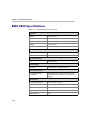
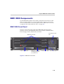
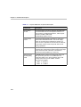
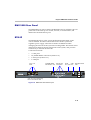
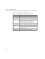
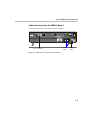
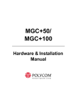
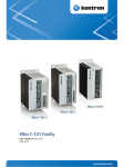
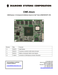
Polycom RMX 2000
Hardware Guide
Version 1.1
Copyright © 2007 Polycom, Inc.
All Rights Reserved
Catalog No. DOC2160A
Version 1.1
Proprietary and Confidential
The information contained herein is the sole intellectual property of Polycom, Inc. No distribution, reproduction or
unauthorized use of these materials is permitted without the expressed written consent of Polycom, Inc. Information
contained herein is subject to change without notice and does not represent commitment of any type on the part of
Polycom, Inc. Polycom and Accord are registered trademarks of Polycom, Inc.
Notice
While reasonable effort was made to ensure that the information in this document was complete and accurate at the
time of printing, Polycom, Inc., cannot assume responsibility for any errors. Changes and/or corrections to the
information contained in this document may be incorporated into future issues.Portions, aspects and/or features of this
product are protected under United States Patent Law in accordance with the claims of United States Patent No: US 6,300,973;
US 6,496,216; US 6,757,005; US 6,760,750; and US 7,054,620.
PATENT PENDING
Regulatory Notices
United States Federal Communication
Commission (FCC)
CE Mark R&TTE Directive
Part 15: Class A Statement. This equipment has
been tested and found to comply with the limits for a
Class A digital device, pursuant to Part 15 of the FCC
Rules. Test limits are designed to provide reasonable
protection against harmful interference when the
equipment is operated in a commercial environment.
This equipment generates, uses and can radiate
radio-frequency energy and, if not installed and used
in accordance with the instruction manuals, may
cause harmful interference to radio communications.
Operation of this equipment in a residential area is
likely to cause harmful interference, in which case the
user will be required to correct the interference at his
or her own expense.
Polycom Inc., declares that the Polycom RMX 2000 is
in conformity with the following relevant harmonized
standards:
Part 68: Network Registration Number. This
equipment is registered with the FCC in accordance
with Part 68 of the FCC Rules. This equipment is
identified by the FCC registration number.
If requested, the FCC registration Number and REN
must be provided to the telephone company.
Any repairs to this equipment must be carried out by
Polycom Inc. or our designated agent. This
stipulation is required by the FCC and applies during
and after the warranty period.
•
United States Safety Construction Details:
Unit is intended for RESTRICTED ACCESS
LOCATION.
•
Unit is to be installed in accordance with the
National Electrical Code.
•
The branch circuit overcurrent protection shall
be rated 20 A for the AC system.
•
This equipment has a maximum operating
ambient of 40°C, the ambient temperature in
the rack shall not exceed this temperature.
To eliminate the risk of battery explosion, the battery
should not be replaced by an incorrect type.
Dispose of used batteries according to their
instructions.
EN 60950-1:2001
EN 55022: 1998+A1:2000+A2:2003 class A
EN 300 386 V1.3.3: 2005
Following the provisions of the Council Directive
1999/CE on radio and telecommunication terminal
equipment and the recognition of its conformity.
Canadian Department of Communications
This Class [A] digital apparatus complies with
Canadian ICES-003.
Notice: The Industry Canada label identifies certified
equipment. This certification means that the
equipment meets telecommunication network
protective, operational and safety requirements as
prescribed in the appropriate Terminal Equipment
Technical Requirements document(s). The
Department does not guarantee the equipment will
operate to the user's satisfaction.
Before installing this equipment, users should ensure
that it is permissible to be connected to the facilities
of the local telecommunications company. The
equipment must also be installed using an acceptable
method of connection. The customer should be
aware that compliance with the above conditions may
not prevent degradation of service in some situations.
Repairs to certified equipment malfunctions, may give
the telecommunications company causes to request
the user to disconnect the equipment.
Users should ensure for their own protection that the
electrical ground connections of the power utility,
telephone lines and internal metallic water pipe
system, if present, are connected together. This
precaution may be particularly important in rural
areas.
Caution: Users should not attempt to make such
connections themselves, but should contact the
appropriate electric inspection authority, or
electrician, as appropriate.
Regulatory Notices
Chinese Communication Certificate
Polycom RMX 2000 Hardware Guide
Table of Contents
Hardware Description . . . . . . . . . . . . . . . . . . . . . . . . . . 1-1
Main Features .......................................................................................... 1-1
RMX 2000 Specifications ....................................................................... 1-2
Site Requirements ................................................................................... 1-3
Safety Requirements ...................................................................... 1-3
Rack Mount Safety Precautions .................................................... 1-3
Installation Precautions ................................................................. 1-4
RMX 2000 Components ......................................................................... 1-5
RMX 2000 Front Panel ................................................................... 1-5
RMX 2000 Rear Panel ..................................................................... 1-7
RTM IP ............................................................................................. 1-7
Cables Connected to the RTM IP Board .............................. 1-9
RMX 2000 LEDs .................................................................................... 1-10
RMX 2000 Front Panel LEDs ....................................................... 1-10
RMX 2000 Rear Panel LEDs ........................................................ 1-11
Component Replacement .................................................................... 1-13
Replacing the CPU (CNTL) Module .......................................... 1-14
Replacing a Functional MPM Module ....................................... 1-15
Replacing the Power Supply Drawer ........................................ 1-16
Replacing the Fan Drawer ........................................................... 1-17
Replacing the RTM IP Board ...................................................... 1-18
i
Table of Contents
ii
1
Hardware Description
This Hardware Guide provides information on the RMX 2000 and its
components. This system utilizes a modular “universal slot” platform,
whose components are designed for high performance, capacity and
reliance.
Main Features
The Polycom RMX 2000 offers the following features:
•
Linux® based
•
Chassis based on the ATCA standard
•
Support for a large number of ports
•
New hardware technologies
•
Telco grade high availability, redundancy, on-line upgrading and
dynamic resource allocation
•
Easy integration of conference elements into external network
management
•
H.323 & SIP video
•
Enhanced Continuous Presence (multi-image video)
•
IVR (Interactive Voice Response) module
1-1
Chapter 1- Hardware Description
RMX 2000 Specifications
Table 1-1
Polycom RMX 2000 Specifications
Physical
Height
3U (13.28 cm.)
Width
19” (48.26 cm.)
Depth
15.74” (40 cm.)
Weight
Up to 16.5 Kg.
Free space above MCU
3” standard installation
IP Protocols
Audio
G.711, G.722, G.722.1, G.729A, G.723.1, Siren14
Video
H.263, H.264
Network Interfaces
IP
H.323 and SIP
Power Supply
AC Input
100-240 VAC, 4-2 AMP, 50/60 Hz
Power Consumption
AC Maximum Power
consumption
AC Voltage–up to 7 AMP at 110 VAC, and 4
AMP 220 VAC protected by a 10 Amp circuit
breaker.
Environment
1-2
Operating temperature
0°– 40°C (22°– 104°F)
Storage temperature
-30°– 70°C (40°– 158°F)
Relative humidity
15% - 90% no condensing
Operating altitude
Up to 3,000 m (10,000 ft.)
Operating ESD
4 kV
Polycom RMX 2000 Hardware Guide
Site Requirements
This section describes the requirements your site must meet for safe
installation and operation of the system.
Safety Requirements
For your protection, please read these safety instructions completely
before operating the equipment.
•
Look carefully for potential hazards in your work area: moist floors,
ungrounded power cables, frayed power cords, missing safety
grounds and so forth.
•
Locate the main circuit breaker within the room.
•
Locate the emergency power OFF switch within the room.
•
Never assume that power is disconnected from a circuit.
•
Use only the power cord supplied with the system.
•
The power cord should only be connected to a power outlet that has a
protective ground contact.
•
Ensure that the power cord is easily accessible from the back of the
system at all times.
•
Place the equipment in a well-ventilated area where the vents are free
from obstruction.
•
Do not place heavy objects directly on top of the RMX 2000 unit.
•
Do not use liquids around your equipment.
Rack Mount Safety Precautions
The following precautions should be followed with regards to rack mount
safety:
•
Keep the area around the RMX 2000 clean and free of clutter.
•
Decide on a suitable location for the equipment rack that will hold the
RMX 2000 unit. It should be situated in a clean, dust-free area that is
well ventilated. Avoid areas where heat, electrical noise and
electromagnetic fields are generated. You will also need it placed
near a grounded power outlet.
•
Ensure that the leveling jacks on the bottom of the rack are fully
extended to the floor with the full weight of the rack resting on them.
1-3
Chapter 1- Hardware Description
•
In a single rack installation, stabilizers should be attached to the rack.
•
In multiple rack installations, the racks should be coupled together.
•
Always make sure the rack is stable before extending a component
from the rack.
•
You should extend only one component at a time - extending two or
more simultaneously may cause the rack to become unstable.
•
Before you install the rails, determine the placement of each
component in the rack.
•
Install the heaviest components on the bottom of the rack first, and
then work up.
•
Allow the power supply units to cool before touching them.
•
Always keep the rack’s trays and board’s closed when not servicing,
to maintain proper cooling.
Installation Precautions
The following precautions should be followed with regards to installation
of the RMX 2000:
1-4
•
Use a regulating uninterruptable power supply (UPS) to protect the
RMX 2000 from power surges and voltage spikes, to keep your MCU
operating in case of a power failure.
•
Place the RMX 2000 on a hard, flat surface such as a desktop or mount
it on 19” rack.
•
The airflow of the RMX 2000 is from left to right. Be sure that the
areas in the left and right side of the system are clear for proper
ventilation.
Polycom RMX 2000 Hardware Guide
RMX 2000 Components
On the RMX 2000 modules are located on both the front and rear of the
MCU as listed in Table 1-2, "Polycom RMX 2000 Component Description".
For more information see the descriptions of the "RMX 2000 Front Panel”
on page 1-5 and "RMX 2000 Rear Panel” on page 1-7.
RMX 2000 Front Panel
Figure 1-1 shows the front panel of the RMX 2000. The front panel
provides access to the RMX 2000 main CNTL modules, MPM modules,
Power Supply drawer, Status LEDs, and Fans.
MPM Boards & LEDs
Power supply drawer
USB ports - are only
for debugging and not
for customer use
Fan drawer & Power
LED
Control Unit & LEDs
2nd CPU & LEDs
Figure 1-1 RMX 2000 Front Panel
1-5
Chapter 1- Hardware Description
Table 1-2
Polycom RMX 2000 Component Description
Component
Description
CPU (CNTL)
Module
The CPU Module controls and manages the RMX 2000.
The CPU Module has an ComExpress Pentium-M 1.4
GHz processor, a 40GB hard disk drive, 1GB Compact
Flash and 512MB of DDR RAM.
The Operating System is Linux.
Power Supply
Drawer
The Power Supply Module is housed in a drawer and
located below the MPM Modules. The Power Supply
drawer is connected to the backplane by means of a
power connector. Operates at 100-240 volts AC 50/60 Hz,
and provides +48VDC 700W output with built-in load
sharing capabilities.
Fan Drawer
Three fans are mounted sideways in the right front panel.
Three fans are mounted in the drawer. Airflow is from right
to left, and out the side of the MCU. The drawer is
connected to the back plane by a connector.
Multi Processor
Module (MPM)
Board
The MPM Boards, perform the various RTP, audio and
video processing functions on the RMX 2000 unit.
Boards are based on the ATCA standard, with a card
manager (CM) and up to 26 720Mhz TI DSP’s.
Two types are available:
• MPM - F - 26 DSP’s
•
1-6
MPM - H - 13 DSP’s
Polycom RMX 2000 Hardware Guide
RMX 2000 Rear Panel
The RMX 2000 rear panel contains the RTM IP board. In addition, the rear
panel houses the main power switch, AC inlet, a circuit breaker, and
additional communications ports.
RTM IP
The RTM IP board provides system shelf management based on the
ATCA standard. It controls and monitors fans on the system and
regulates power supply. This board contains an Ethernet Switch
managing the network of the system and routing traffic. This board routes
data between the boards and components of the system, and provides
connectivity to external IP networks.
Connections include:
•
3 LAN ports
•
10/100Mb ShMC connection (Future Use)
•
1 Serial port (Future Use)
•
1 USB port
LAN 1-3 &
LEDs
10/100Mb ShMC
Internal LAN
LAN & LEDs - NA* connections
USB
Serial
Port - NA* Port
Standby button &
LED
* NA- are only for debugging
and not for customer use
Figure 1-2 RMX 2000 Rear Panel Layout
1-7
Chapter 1- Hardware Description
The following items appear on the RMX 2000 rear panel:
Table 1-3
1-8
RMX 2000 Rear Panel - RTM IP Component Description
Function Name
Description
LAN 1
NA - Disconnected.
LAN 2
Used for the Network connection.
LAN 3
For Remote Access only using the Permanent
Management Network. For more information, see the
RMX 2000 Administrator’s Guide, Appendix F:
"Permanent Management Network” on page F-1.
10/100 ShMC
NA - For debugging purposes only.
Serial
NA - For debugging purposes only.
USB
USB key connection. For more information, see the RMX
2000 Getting Started Guide, "First Time Installation and
Configuration” on page 2-1.
Standby button
Toggle between CPU activation and standby
Polycom RMX 2000 Hardware Guide
Cables Connected to the RTM IP Board
All external connectors are located on the rear panel.
LAN 2 Connection
Off/On
switch
Power
Cable
Figure 1-3 RMX 2000 Rear Panel View with Cables
1-9
Chapter 1- Hardware Description
RMX 2000 LEDs
The RMX includes LEDs located on the front panel and rear panel. In the
front panel, the LEDs reflect the state of the module. The LEDs on the rear
panel indicate the state of the external connections and the status of the
RTM IP board
RMX 2000 Front Panel LEDs
The following items appear on the RMX 2000 front panel:
Table 1-4
RMX 2000 Front Panel LED’s
Function Name
LED ID
LED Color
Description
Green
OK.
Red
Warning - Fan failure.
Green
OK.
Red
Error - Problem with power supply.
ERR
Red
ON - Major system error.
RDY
Green
ON - CPU board has successfully
completed startup.
ACT
Amber
ON - At least one endpoint is
connected to the system.
HD
Red
OFF - Normal
Fan Status
Power Status
CNTL
Flashes - Hard disk is active
HS
Blue
Flashes - Shut down process
initiated when pulling the CPU
ejector mechanism.
ON - CPU may be removed.
1-10
Polycom RMX 2000 Hardware Guide
Table 1-4
RMX 2000 Front Panel LED’s (Continued)
Function Name
LED ID
LED Color
Description
MPM
ERR
Red
ON - Major error on board.
RDY
Green
ON - The board has completed
startup successfully.
ACT
Amber
ON - At least one participant is
connected to a conference.
HS
Blue
ON - The card can be removed
safely once the CPU ejector
mechanism is activated.
RMX 2000 Rear Panel LEDs
The following items appear on the RMX 2000 rear panel:
Table 1-5
RMX 2000 Rear Panel LEDs
Function Name
LED
Name
LED Color
Description
LAN LEDs (1-3)
LNK
Green
Lit with active network
connection, flickers with Packet
activity.
1 Gb
Amber
Lit when 1Gb connection online,
flickers with Packet activity
LNK
Green
Lit with active network
connection, flickers with Packet
activity.
100
Amber
Lit when active network is 10/
100Mb, flickers with Packet
activity.
10/100 ShMC
LEDs
1-11
Chapter 1- Hardware Description
Table 1-5
RMX 2000 Rear Panel LEDs (Continued)
Function Name
SLOT (1-4)
LEDs
ShMC LEDs
LED
Name
LED Color
Description
LNK (1-4)
Green
Lit with active network
connection, flickers with Packet
activity.
1Gb (1-4)
Amber
Lit when 1Gb connection online,
flickers with Packet activity.
ERR
Red
ON - Major error on RTM board.
ACT
Red
ON - Packet flow to and from
the MCU chassis.
RDY
Green
ON - RTM IP board has
successfully completed startup.
HS
Blue
OFF - Normal.
Flashes - During shut down
process. This is activated by
light push on the RTM IP
board’s ejector mechanism.
ON - RTM IP board may be
removed.
Standby LED
1-12
Red
ON - CPU & System are in a
standby (OFF) mode.
Polycom RMX 2000 Hardware Guide
Component Replacement
The RMX 2000 is designed with ease of maintenance in mind. Most
components are swappable and are accessible directly via the front panel
or the rear panel.
The following components can be replaced when they are faulty:
•
CPU (CNTL) Module
•
Multi Processor Module (MPM) Board(s)
•
Power Supply Module
•
Fan Drawer
RTM IP Board
Warning!
• All maintenance tasks are to be performed by qualified, authorized
personnel.
•
•
Use only replacement parts supplied by your dealer.
Follow all procedures. Do not skip any steps.
Before replacing parts:
•
To ensure a part needs replacing, complete the troubleshooting
procedures.
•
Identify exactly which part needs replacing.
•
Make sure you have the correct replacement part on hand.
•
Make sure you are using proper ESD equipment, to prevent damage
to the system.
1-13
Chapter 1- Hardware Description
Replacing the CPU (CNTL) Module
The CPU module is the management system of the RMX 2000. Use the
following procedure to replace a CPU (CNTL) Module:
1-14
1
Ensure that power switch to the RMX 2000 is turned OFF (O).
2
Unscrew the screws on the front panel of the RMX 2000 that secure
the CPU (CNTL) Module.
3
Use the metal ejectors to pull the CPU (CNTL) Module out of its slot
in the Backplane.
4
Carefully slide the CPU (CNTL) Module out through the front panel.
5
Slide in the replacement CPU (CNTL) Module.
6
Push the CPU (CNTL) Module firmly into the Backplane, making
sure it is properly seated in its slot.
7
Ensure that the metal ejectors are fully retracted into their housings.
8
Tighten the screws on the front panel of the RMX 2000 that secure the
Functional CPU (CNTL) Module.
9
Turn ON the RMX 2000.
Polycom RMX 2000 Hardware Guide
Replacing a Functional MPM Module
Use the following procedure to replace a faulty MPM Module types F
or H:
1
Ensure that power switch to the RMX is turned OFF (O).
2
Unscrew the screws on the front panel of the RMX that secure the
MPM Module.
3
Use the metal ejectors to pull the MPM Module out of its slot in the
Backplane.
4
Carefully slide the MPM Module out through the front panel.
5
Slide in the replacement MPM Module.
6
Push the MPM Module firmly into the Backplane, making sure it is
properly seated in its slot.
7
Ensure that the metal ejectors are fully retracted into their housings.
8
Tighten the screws on the front panel of the RMX that secure the
MPM Module.
9
Turn ON the RMX.
1-15
Chapter 1- Hardware Description
Replacing the Power Supply Drawer
A single supply unit powers the RMX 2000. Use the following procedure
to replace a Power Supply:
1-16
1
Ensure that power switch to the RMX 2000 is turned OFF (O).
2
Unscrew the screws on the front panel of the RMX 2000 that secure
the Power Supply.
3
Use the metal ejectors to pull the Power Supply Module out of its slot
in the Backplane.
4
Carefully slide the Power Supply Module out through the front
panel.
5
Slide in the replacement Power Supply Module.
6
Push the Power Supply Module firmly into the Backplane, making
sure it is properly seated in its slot.
7
Ensure that the metal ejectors are fully retracted into their housings.
8
Tighten the screws on the front panel of the RMX 2000 that secure the
Power Supply Module.
9
Turn ON the RMX 2000.
Polycom RMX 2000 Hardware Guide
Replacing the Fan Drawer
Three fans are mounted in the Fan Drawer, where the airflow is from right
to left. Should one of these fans fail as indicated by a Fan LED, you are
required to replace the fan drawer.
1
Unscrew the screws on the front panel of the RMX 2000 that secure
the Fan Drawer.
2
Use the metal ejectors to pull the Fan Drawer out of its slot in the
Backplane.
3
Carefully slide the Fan Drawer out through the front panel.
Warning!
The Fan drawer can be replaced when the RMX unit is ON, however a
replacement drawer must be inserted immediately. The temperature increase is
detected by the system, when critical, a system shutdown is initiated.
4
Slide in the replacement Fan Drawer.
5
Push the Fan Drawer firmly into the Backplane, making sure it is
properly seated in its slot.
6
Ensure that the metal ejectors are fully retracted into their housings.
7
Tighten the screws on the front panel of the RMX 2000 that secure the
Fan Drawer.
1-17
Chapter 1- Hardware Description
Replacing the RTM IP Board
The RTM IP board on the rear of the RMX 2000 provides connectivity to
all the MCU modules. Use the following procedure to replace the RTM IP
board:
1-18
1
Ensure that power switch to the RMX 2000 is turned OFF (O).
2
Unscrew the screws on the rear panel of the RMX 2000 that secure the
RTM IP board.
3
Use the metal ejectors to pull the RTM IP board out of its slot in the
Backplane.
4
Carefully slide the RTM IP board out through the rear panel.
5
Slide in the replacement RTM IP board.
6
Push the RTM IP board firmly into the Backplane, making sure it is
properly seated in its slots.
7
Ensure that the metal ejectors are fully retracted into their housings.
8
Tighten the screws on the rear panel of the RMX 2000 that secure the
RTM IP board.
9
Turn ON the RMX 2000.