1
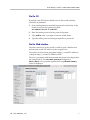
VIEW Certified Configuration Guide
Aruba
Mobility Controllers
A200, A800, A2400, A6000
June 2008 Edition
1725-36080-001
Revision J
Configuration Guide
Trademark Information
Notice
Polycom® and the logo designs
SpectraLink®
LinkPlus
Link
NetLink
SVP
Are trademarks and registered trademarks of
Polycom, Inc. in the United States of America
and various countries. All other trademarks
used herein are the property of their respective
owners.
Polycom, Inc. has prepared this document for
use by Polycom personnel and customers. The
drawings and specifications contained herein
are the property of Polycom and shall be neither
reproduced in whole or in part without the prior
written approval of Polycom, nor be implied to
grant any license to make, use, or sell equipment
manufactured in accordance herewith.
Patent Information
The accompanying product is protected by one
or more US and foreign patents and/or pending
patent applications held by Polycom, Inc.
Copyright Notice
Copyright © 2006 to 2008 Polycom, Inc.
All rights reserved under the International and
pan-American copyright Conventions.
No part of this manual, or the software
described herein, may be reproduced or
transmitted in any form or by any means, or
translated into another language or format, in
whole or in part, without the express written
permission of Polycom, Inc.
Do not remove (or allow any third party to
remove) any product identification, copyright or
other notices.
Polycom reserves the right to make changes in
specifications and other information contained
in this document without prior notice, and the
reader should in all cases consult Polycom to
determine whether any such changes have been
made.
No representation or other affirmation of fact
contained in this document including but not
limited to statements regarding capacity,
response-time performance, suitability for use,
or performance of products described herein
shall be deemed to be a warranty by Polycom
for any purpose, or give rise to any liability of
Polycom whatsoever.
Contact Information
Please contact your Polycom Authorized
Reseller for assistance.
Polycom, Inc.
4750 Willow Road,
Pleasanton, CA 94588
http://www.polycom.com
Every effort has been made to ensure that the
information in this document is accurate.
Polycom, Inc. is not responsible for printing or
clerical errors. Information in this document is
subject to change without notice and does not
represent a commitment on the part of Polycom,
Inc.
2
PN: 1725-36080-001_J.doc
Aruba Mobility Controllers: A200, A800, A2400, A6000
Introduction
Polycom’s Voice Interoperability for Enterprise Wireless (VIEW)
Certification Program is designed to ensure interoperability and high
performance between SpectraLink Wireless Telephones and WLAN
infrastructure products. The products listed below have been
thoroughly tested in Polycom’s lab and have passed VIEW
Certification. This document details how to configure the Aruba
mobility controller with SpectraLink Wireless Telephones.
Certified Product Summary
Manufacturer:
Aruba Networks http://www.arubanetworks.com
Approved products:
Controllers
Access Points
A200
A800
A2400
A6000 †
AP41
AP60
AP61
AP65
AP70 †
RF technology:
802.11b/g/a
Radio:
2.4 GHz (802.11 b/g), 5 GHz (802.11a)
Security:
WPA2-PSK
AP firmware version certified:
2.5.4.0
SpectraLink handset models certified: **
e340/h340/i640
8020/8030
SpectraLink handset software certified:
89.134
122.010 or greater
SpectraLink radio mode:
802.11b
Maximum telephone calls tested per AP:
†
802.11b
802.11g
12
12
802.11a
*
Network topology:
Switched Ethernet (recommended)
Denotes products directly used in VIEW Certification testing.
* Maximum calls tested during VIEW Certification and the recommended setting in the SpectraLink 8000 SVP
Server. The certified product may actually support a higher number of calls for 802.11a and 802.11g radio modes.
** SpectraLink handset models 8020/8030, e340/h340/i640 and their OEM derivates are VIEW Certified with the
WLAN hardware and software identified in the table. Throughout the remainder of this document they will be
referred to collectively as “SpectraLink Wireless Telephones”.
Customer Service
If you encounter difficulties or have questions regarding the
configuration process, please contact Aruba Networks technical
support at 1-800-943-4526, visit www.arubanetworks.com/support or
e-mail [email protected].
PN: 1725-36080-001_J.doc
3
Configuration Guide
Network Topology
It is important to note that this configuration is not necessarily
applicable to all customer environments.
The following topology was tested during VIEW Certification testing.
Known Limitations
No limitations were discovered during VIEW Certification testing.
VIEW Certification testing verifies that the wireless telephone and the
AP interoperate at the packet level; therefore, no add-on vendor
features were tested in the scope of VIEW.
4
PN: 1725-36080-001_J.doc
Aruba Mobility Controllers: A200, A800, A2400, A6000
Deployment Description
It is a SpectraLink requirement that voice users be placed on a
separate VLAN (e.g., VLAN 10) and data users on a separate VLAN
(e.g., VLAN 25). The voice and data VLANs reside on the Aruba
mobility controller and not on the access points (APs). The user traffic
is tunneled back to the Aruba controller for processing. The edge
network thus does not have to be modified to accommodate the WiFi
clients and the VoWiFi network. Map each VLAN to a unique subnet.
The mobility controller (switch) IP address needs to be set via the
loopback interface setting. The Controller’s loopback address must be
a routable address so that the APs can reach this address.
Interface setting
Identify the mobility controller port that serves as the uplink port for
the data VLAN. The physical port used in this example is Fast
Ethernet 1/0. This port is configured as a trunk port with both the
voice and data VLAN.
Default route
The L3 switch connected to the Aruba controller serves as the default
gateway for all the WiFi clients. Configure the default route to the
next-hop gateway connected to the mobility controller.
Physical interface
All interfaces that connect to the core networks, routers, servers and
gateways need to be set as trusted ports.
Connecting the APs
The APs need an IP address for communication with the mobility
controller. The APs can connect to the controller over a L2 or L3
network. Ensure that DHCP is enabled on the subnets the APs are
connected to and the APs can ping the Aruba mobility controller’s
“switch IP address” from their current subnet.
PN: 1725-36080-001_J.doc
5
Configuration Guide
Connecting to the Mobility Controller
Command, comment, and screen text key
In the sections below you will find commands, comments, prompts,
system responses, or other screen-displayed information involved in
the configuration process. This key explains the text styles and
symbols used to denote them.
Text Style
Denotes:
xxxxxxxx
Typed command
<xxxxxxxx>
Encryption key, domain name or other information
specific to your system that needs to be entered
(xxxxxxxx)
Comment about a command or set of commands
xxxxxxxx
Prompt, system response or other displayed information
Via console
1. Using a standard RS-232 cable, connect the Aruba mobility
controller to the serial port of a terminal or PC.
2. Run a terminal emulation program (such as HyperTerminal™) or
use a VT-100 terminal with the following configuration:
Bits per second:
Data bits:
Parity:
Stop bits:
Flow control:
9600
8
None
1
None
3. Press Enter to display the Aruba mobility controller login screen.
4. Enter the default login: admin and the default password: admin.
These are case sensitive.
5. Enter enable and the default password: admin to get into the
command mode.
6
PN: 1725-36080-001_J.doc
Aruba Mobility Controllers: A200, A800, A2400, A6000
Via the CLI
By default, only SSH (Secure Shell) access to the switch (mobility
controller) is permitted.
1. From a management system that has network connectivity to the
switch, connect to the switch using SSH:
ssh admin@<switch IP address>
2. Enter the admin password at the password prompt.
3. Type enable at the > prompt to enter the enable mode.
4. Type the enable password when prompted for a password.
Via the Web interface
Once the connectivity to the switch is verified, open a Web browser
and enter the switch’s IP address in the navigator bar.
The switch can be accessed using http at http://<switch IP Address>
or https at https://<switch IP Address>:4343.
The user is prompted with the username and password configured (in
the example above, the username/password configured is
admin/admin). On successful login the following Network Summary
screen is displayed:
PN: 1725-36080-001_J.doc
7
Configuration Guide
Initial Setup
Before starting, please ensure that the Policy Enforcement Firewall
module license is enabled on the Aruba mobility controller. Please
contact Aruba Networks for licenses and installation information.
On power-up, the user is presented with the startup wizard:
Enter System name [Aruba800]: Aruba
Enter VLAN 1 interface IP address [172.16.0.254]:
Enter VLAN 1 interface subnet mask [255.255.255.0]:
Enter IP Default gateway [none]:
Enter Switch Role, (master|local) [master]: master
Enter Country code (ISO-3166), <ctrl-I> for supported
list: US
You have chosen Country code US for United States
(yes|no)?: yes
Enter Password for admin login (up to 32 chars): admin
Re-type Password for admin login: admin
Enter Password for enable mode (up to 15 chars): enable
Re-type Password for enable mode: enable
Do you wish to shutdown all the ports (yes|no)? [no]: no
Current choices are:
System name: Aruba
VLAN 1 interface IP address: 172.16.0.254
VLAN 1 interface subnet mask: 255.255.255.0
IP Default gateway: none
Switch Role: master
Country code: US
Ports shutdown: no
If you accept the changes the switch will restart!
Type <ctrl-P> to go back and change answer for any
question
Do you wish to accept the changes (yes|no)yes
8
PN: 1725-36080-001_J.doc
Aruba Mobility Controllers: A200, A800, A2400, A6000
. . . . .
<<<<<
Welcome to Aruba Wireless Networks - Aruba 800
>>>>>
. . . .
(Aruba)
User:
PN: 1725-36080-001_J.doc
9
Configuration Guide
Assigning an IP to the Mobility Controller
1. Connect to the switch via the CLI.
2. Login with the configured username and password, admin/admin
in this example.
3. Type enable at the > prompt.
4. Type the enable password, enable in this example.
5. Type configure terminal at the # prompt.
6. Create the VLAN for the voice (vlan 25) using the VLAN
command:
(Aruba) (config) #vlan 25
7. Create the VLAN interface.
(Aruba) (config) #interface vlan 25
8. Assign the IP address to the interface.
(Aruba) (config-subif)#ip address 10.168.10.2
255.255.255.0
9. Create the loopback interface and assign an IP address to the
loopback. For more information about the loopback interface refer
to the user guide.
(Aruba) (config) #interface loopback
(Aruba) (config-loop)#ip address 10.168.10.1
Switch IP Address is Modified. Switch should be
rebooted now
(Aruba) (config-loop)#!
(Aruba) (config) #ip default-gateway 10.168.10.10
10. Assign a physical interface to the VLAN. In this example, the
interface connecting to the network is a trunk interface. Configure
the mode on the interface to a trunk mode.
(Aruba)
(Aruba)
(Aruba)
(Aruba)
(Aruba)
10,25
(Aruba)
(config) #interface fastethernet 1/0
(config-if)#trusted
(config-if)#no shutdown
(config-if)#switchport mode trunk
(config-if)#switchport trunk allowed vlan add
(config-if)#!
(Aruba) (config)#
11. Ping the default gateway from the switch’s console.
12. Ping the switch’s IP address from the management station.
10
PN: 1725-36080-001_J.doc
Aruba Mobility Controllers: A200, A800, A2400, A6000
Connecting APs
Provisioning APs
The APs need to be provisioned. The Aruba APs can be provisioned
manually or be configured for automatic provisioning. For manual
provisioning, use the Web-based AP provisioning Web page. Refer to
the AP Provisioning User Guide for instructions on provisioning the
AP.
The APs can communicate with the controller over a L2 or L3
network. The only requirement is that each AP be assigned an IP
address and default gateway using DHCP.
PN: 1725-36080-001_J.doc
11
Configuration Guide
SSID Configuration
CLI command configuration
APs can be configured using the CLI or the Web interface. Each AP is
identified by a unique location code. The APs can either be configured
per location with unique settings using the AP’s unique location code
or globally using the wildcard location. “0” is used as the wildcard.
Example: ap location 0.0.0 will configure all Aruba APs on the
WLAN system. Both the Aruba APs and the Spectralink handsets
support the 802.11a and the 802.11b/g radios. To apply the SSID to
both bands configure the SSID as follows:
configure terminal
ap location x.y.z
virtual-ap aruba vlan-id 26 opmode wpa2-aes-psk
wpa-passphrase thisisthekey dtim-period 3
If the voice network needs to exist only in the 802.11a band ,
configure the virtual AP under the 802.11a settings on the controller.
configure terminal
ap location x.y.z
phy-type a virtual-ap aruba vlan-id 26 opmode wpa2-aespsk
wpa-passphrase thisisthekey dtim-period 3
If the voice network needs to exist only in the 802.11g band, configure
the virtual AP under the 802.11g settings on the controller.
configure terminal
ap location x.y.z
phy-type g virtual-ap aruba vlan-id 26 opmode wpa2-aespsk
wpa-passphrase thisisthekey
dtim-period 3
To save changes, enter:
write mem
12
PN: 1725-36080-001_J.doc
Aruba Mobility Controllers: A200, A800, A2400, A6000
Web-based configuration
1. Click the Configuration button.
2. In the navigation pane, select Network from the WLAN sub-menu.
3. To edit an existing AP profile, click the Edit button corresponding
to the SSID.
4. To add a new profile, click the Add button.
5. Under Add SSID, enter aruba in the SSID field.
6. Select 802.11a/b/g from the Radio Type drop-down list to apply the
SSID settings to the a/b/g radio.
7. For the SSID Default VLAN, enter the voice VLAN number.
8. For the DTIM Period, enter 3.
9. Select the AES-CCM option for WPA2-AES-PSK encryption.
10. Under WPA2, select the PSK AES-CCM option.
11. Select PSK Passphrase (alphanumeric) from the Format drop-down
list before typing in the passphrase.
12. Enter the PSK AES Key/Passphrase.
13. Click the Apply button.
Navigating to other pages without saving/applying the changes will
result in the loss of the changes.
PN: 1725-36080-001_J.doc
13
Configuration Guide
Access Point Configuration
Radio setting 802.11b or 802.11g
When using the 802.11b/g band for the VoWiFi network, set the radio
settings to 802.11b/g mixed mode.
Preamble settings
The tests on the Aruba system were run with the short preamble
setting.
The short preamble setting can be used, as this supports both short
and long preambles. SpectraLink Wireless Telephones only support
long preamble when using the 802.11b radio.
When using a dual-radio AP, use the 802.11a radio for data and
802.11b/g for voice if possible, as this will improve the overall
performance.
Channel and Tx power
Channel and Tx power level can be manually set or configured to be
assigned automatically depending on the RF environment. Please
consult your facility’s RF site survey designed for voice to determine
the correct channel, power and data rate settings. SpectraLink
Wireless Telephones require the following minimum dBm reading to
support the corresponding “Required” data rate setting in the access
point.
802.11
Radio Standard
802.11b
802.11g
802.11a
14
Minimum Available
Signal Strength (RSSI)
-70 dBm
Maximum
"Required" Data Rate
1 Mb/s
-60 dBm
11 Mb/s
-63 dBm
6 Mb/s
-47 dBm
54 Mb/s
-60 dBm
6 Mb/s
-45 dBm
54 Mb/s
PN: 1725-36080-001_J.doc
Aruba Mobility Controllers: A200, A800, A2400, A6000
For additional details on RF deployment please see the Deploying
Enterprise-Grade Wi-Fi Telephony white paper and the Best
Practices Guide for Deploying SpectraLink 8020/8030 Wireless
Telephones.
Recommended AP configuration settings
CLI Commands
Required Settings
Default
Settings
0
Max-clients <x>
40
Beacon-interval <x>
Set to default
100
milliseconds
The interval at which beacons
are sent out .
dtim-period <x>
3
1
Delivery Traffic Indication
Message interval in terms of
beacon interval.
hide-essid <enable /
disable>
Enable
Disable
To disable the ESSID from
being broadcasted.
Max-retries
2
4
Maximum number of times the
AP tries to send a packet to the
client before discarding the
packet.
b/g-mode
Mixed
Mixed
The radio mode of the b/g
radio.
Tx-power <0-4>
0
As per the environment. This
need not be set if ARM is
enabled.
Channel <x>
1
This is the channel assigned to
the radio. Need not be set if
ARM is enabled.
802.11b/g rates
These rates should be
determined from RF site
survey. Verify you have
sufficient coverage to
support data rates.
5,11
802.11b/g Tx rates
These rates should be
determined from RF site
survey. Verify you have
sufficient coverage to
support data rates.
1,2,5,11
802.11b/g rates (if all
wireless client are
802.11g)
These rates should be
determined from RF site
survey. Verify you have
sufficient coverage to
support data rates.
5,11
PN: 1725-36080-001_J.doc
Description
Max clients that can associate
with the AP.
The supported Tx rates for
802.11b/g.
15
Configuration Guide
CLI Commands
Required Settings
802.11b/g Tx rates (if
all wireless client are
802.11g)
These rates should be
determined from RF site
survey. Verify you have
sufficient coverage to
support data rates.
802.11a rates
These rates should be
determined from RF site
survey. Verify you have
sufficient coverage to
support data rates.
6,9,12,24
802.11a Tx rates
These rates should be
determined from RF site
survey. Verify you have
sufficient coverage to
support data rates.
6,9,12,18,24,
36,48,54
The supported Tx rates for
802.11a.
ESSID
<voice ssid as configured>
Aruba
This is the ESSID that the voice
devices would associate with.
Short preamble
Tested: Enable
Recommended: Disable
Enable
Set the short preamble to
disable, to enable longpreamble-only support.
16
Default
Settings
1,2,5,11
Description
PN: 1725-36080-001_J.doc
Aruba Mobility Controllers: A200, A800, A2400, A6000
CLI command configuration
All of the commands listed in the CLI Commands column above must
be entered under the ap location command.
The format is:
ap location x.y.z
phy-type g (To make the changes for the “g” radio.)
commands
!
phy-type a (To make the changes for the “a” radio.)
commands
!
Web-based configuration
1. Click the Configuration button.
2. In the navigation pane, select Radio from the WLAN sub-menu.
3. Click the 802.11b/g tab.
4. For Max Retries, enter 2 for voice.
5. Select the Short Preamble check box.
6. For the DTIM period, enter 3.
7. For Basic Rates and Supported Rates, consult the facility’s RF site
survey to determine if coverage is sufficient to support all data
rates.
8. To assign the power and channel setting manually:
a. For ARM Assignment, select Disabled.
b. Clear the ARM Scanning check box.
c. Set the Default Channel and Initial Transmit Power from their dropdown lists.
d. For Mode, click the Access-point option.
9. Click the Apply button.
PN: 1725-36080-001_J.doc
17
Configuration Guide
18
PN: 1725-36080-001_J.doc
Aruba Mobility Controllers: A200, A800, A2400, A6000
10. Click the 802.11 a tab.
11. For Max Retries, enter 2 for voice.
12. For the DTIM period, enter 3.
13. For Basic Rates and Supported Rates, consult the facilities RF site
survey to determine if coverage is sufficient to support all data
rates.
14. To assign the power and channel setting manually:
a. For ARM Assignment, select Disabled.
b. Clear the ARM Scanning check box.
c. Set the Default Channel and Initial Transmit Power from their dropdown lists.
d. For Mode, click the Access-point option.
15. Click the Apply button.
PN: 1725-36080-001_J.doc
19
Configuration Guide
Dynamic RF Management —
ARM Aware Scanning
If Adaptive Radio Resource Management (ARM) Aware Scanning (RF
scanning) is included in your firmware release, it can be enabled
through the command line interface as follows:
configure terminal
ap location x.y.z
phy-type g
arm scanning enable
arm assignment single-band
arm voip-aware-scan enable
phy-type a
arm scanning enable
arm assignment single-band
arm voip-aware-scan enable
write mem
This feature was enabled during VIEW Certification testing in a
screen room (strong signals in a clean environment). A real-world
test with interfering RF signals was not simulated.
20
PN: 1725-36080-001_J.doc
Aruba Mobility Controllers: A200, A800, A2400, A6000
Security Policies and QoS
Once the basic infrastructure is configured, it is necessary to configure
the security policies to ensure that the data network and the voice
network are secured and access to these networks is limited as
required.
The steps are as follows:
1. Setup aliases for the SVP Server.
2. Set policies for the wireless telephone user to the required voice
server, DHCP and TFTP servers. Add other ACLs as required to
permit other traffic from the wireless telephones.
3. Assign policies to the role.
Create an alias for the SVP Server
1. Click the Configuration tab.
2. In the navigation pane, select Advanced from the Security sub-menu.
3. Click the Destinations tab.
4. To add a new destination, click the Add button.
5. Create a new net-destination at Destination Name (e.g. svp_server),
and add the SVP servers as hosts.
For more details on configuring the net-destinations, refer to the user
guide.
PN: 1725-36080-001_J.doc
21
Configuration Guide
Create policies for the wireless telephone user
The policies shown in the above example can be configured using the
Web interface as follows:
22
PN: 1725-36080-001_J.doc
Aruba Mobility Controllers: A200, A800, A2400, A6000
Assign policies to the role
Create a role, for example phones, and assign the policies to this role.
This is the role that would be assigned to the handsets when they are
authenticated successfully.
The Security Policies and QoS can also be configured through the
command line interface (CLI). The CLI commands corresponding to
this section are as follows:
configure terminal
netdestination tftp-server
host 10.168.0.20
!
netdestination svp_server
host 10.168.0.11
host 10.168.0.12
!
netdestination dhcp-server
host 10.168.0.21
!
ip access-list session phone_acl
user user any deny
user alias svp_server svc-svp permit queue high
PN: 1725-36080-001_J.doc
23
Configuration Guide
alias svp_server user svc-svp permit queue high
user alias tftp-server svc-tftp permit
user alias dhcp-server svc-dhcp permit
user host 224.0.1.116 any permit
!
user-role phones
session-acl phone_acl
!
24
PN: 1725-36080-001_J.doc
Aruba Mobility Controllers: A200, A800, A2400, A6000
Authentication
In addition to the encryption, Aruba recommends the use of MAC
authentication to authenticate the Spectralink handsets. On the Aruba
System, the roles for SpectraLink Wireless Telephones are derived
using MAC-authentication. The wireless telephones can be
authenticated individually using MAC-authentication or as a group
using the vendor OUI and derivation rules. For instruction on
enabling MAC-authentication refer to Aruba’s user guide.
For the OUI based derivation rule, configure the following from the
CLI:
aaa derivation rules user
set role condition macaddr starts-with "00:90:7a" setvalue phone
PN: 1725-36080-001_J.doc
25
Configuration Guide
Quality of Service (QoS)
Quality of service is achieved by prioritizing the SpectraLink voice
traffic over data traffic. To prioritize the voice traffic over data traffic
in the AP traffic queues, the “queue high” tag is used at the end of
each ACL to prioritize the traffic matching the ACL over all other
traffic. In the example shown above:
user alias svp_server svc-svp permit queue high
alias svp_server user svc-svp permit queue high
The traffic that matches the above two rules is prioritized over all
other traffic. In addition, a DiffServ tag or a Dot1p tag can be
configured at the end of each ACL to indicate the relative priority of
the traffic to the traffic to the network.
Example :
user
alias svp_server svc-svp permit dot1p 4 queue
high dot1p-priority 4 tos 4 queue high
alias svp_server user svc-svp permit queue high dot1ppriority 4 tos 4 queue high
By default, the packets are not tagged.
In addition multicast/bradcast traffic in the air can be limited by
turning on the firewall voip-prox-arp. This command is available on
the CLI alone.
(Aruba)# configuration terminal
(Aruba) (config)# firewall voip-proxy-arp
26
PN: 1725-36080-001_J.doc
Aruba Mobility Controllers: A200, A800, A2400, A6000
Subnet Roaming
The Aruba system can be set up to support inter-switch inter-subnet
roaming. The topology is as shown in the figure on page 2.
When two or more switches are used in the Aruba WLAN system,
one switch has to be identified as the master and the others as the
local switch. During VIEW Certification testing, the Aruba 800 was
configured as the master switch and the Aruba 6000 was configured
as a local switch; therefore, this configuration is used in the following
examples.
For instructions on setting up a switch as a local switch refer to
Aruba’s user guides.
Ensure that both switches have IP connectivity. A simple ping from
each of the switches to the other switch can be used to verify
connectivity. In a master local setup all AP, authentication, and
firewall configurations will be made on the master and pushed down
to the local switch.
In the configuration tested, all APs with location code 1.1.0 were
configured to boot off of the master switch and all APs with location
code 1.2.0 were configured to boot off of the local switch.
To use the Web interface to configure this, do the following:
1. From the master switch, navigate to the Configuration > WLAN >
Advanced tab.
2. Add a new location 1.1.0 and click the Apply button.
3. In the next page click the General tab and set the LMSIP to the
“switch IP” address of the master.
4. Apply the configurations.
5. Configure location 1.2.0 in a similar manner and set the LMSIP
address to the “switch IP” address of the local switch.
6. Create a default route for multicast traffic re-direction on the
switch that acts as the Mobility Home Agent for the Voice group
(this was done on the master switch in the test example).
PN: 1725-36080-001_J.doc
27
Configuration Guide
CLI Commands to Set Up Subnet Roaming
Commands for the master switch (the Aruba 800)
Configure terminal
ip default-gateway <ip_addr of router>
ap location 1.1.0
(#ap connected to 800)
lms-ip <ip_addr of 800 switch>
ap location 1.2.0
(#ap connected to 6000)
lms-ip <ip_addr of 6000 switch>
ip route 224.0.0.0 255.0.0.0 <ip_addr of SpectraLink
gateway>
exit
write mem
Commands for the local switch (the Aruba 6000)
The AP’s IP address must be on the same subnet as the switch.
Configure terminal
masterip <ip address of the master >
interface loopback
ip address <ip_addr of the 6000>
vlan 1
interface vlan 1
ip address <ip_addr of the 6000> <netmask>
interface fastethernet <port>
switchport access vlan 1
(only if the port is an
access port)
trusted
no shut
!
ip default-gateway <ip_addr of router>
!
exit
write mem
After the master switch IP address and the local switch IP address are
configured on the local switch, the switch needs to be rebooted prior
to use.
28
PN: 1725-36080-001_J.doc
Aruba Mobility Controllers: A200, A800, A2400, A6000
It’s also necessary to set the default gateway of the SpectraLink 8000
SVP Server and SpectraLink 8000 Telephony Gateway to the IP
address of the router connected to the master switch.
CLI Commands to Verify Setup for Subnet Routing
From the Aruba 800
show master ip
show stm connectivity
(should be 800’s ip)
(shows the APs connected to
the Aruba 800 switch)
Ping the local switch.
Pings should be successful.
From the Aruba 6000
show master ip
show stm connectivity
(should be 800’s ip)
(shows the APs connected to
the Aruba 6000 switch)
show running configuration (shows the AP & aaa rules are
carried from the master to
the slave)
PN: 1725-36080-001_J.doc
29
Configuration Guide
Checking the Configuration
Verify connectivity by pinging between the switches, the APs, and the
server and gateway.
The switch and AP are now ready for use with the SpectraLink
Wireless Telephones.
To show AP settings:
show ap config location x.y.z
To show all APs connected to a switch:
show stm connectivity
To show clients associated to all APs:
show station-table
To show clients associated to a specific AP:
show ap status <ip of ap>
30
PN: 1725-36080-001_J.doc