1
ArubaOS
User Guide
ArubaOS Version 3.2
Copyright
© 2007 Aruba Networks, Inc. All rights reserved.
Trademarks
Aruba Networks® is a registered trademark, and Mobility Management System,
RFprotect, and Bluescanner are trademarks of Aruba Networks, Inc.
All other trademarks or registered trademarks are the property of their respective
holders.
Specifications are subject to change without notice.
Legal Notice
The use of Aruba Networks, Inc. switching platforms and software, by all
individuals or corporations, to terminate other vendors' VPN client devices
constitutes complete acceptance of liability by that individual or corporation for
this action and indemnifies, in full, Aruba Networks, Inc. from any and all legal
actions that might be taken against it with respect to infringement of copyright on
behalf of those vendors.
Warranty
This hardware product is protected by the standard Aruba warranty of one year
parts/labor. For more information, refer to the ARUBACARE SERVICE AND
SUPPORT TERMS AND CONDITIONS.
Altering this device (such as painting it) voids the warranty.
2
ArubaOS 3.2
User Guide
0510339-02
September 2007
Contents
Preface . . . . . . . . . . . . . . . . . . . . . . . . . . . . . . . . . . . . . . . . . . . . . . . . . .
Document Organization . . . . . . . . . . . . . . . . . . . . . . . . . . . . . . . . . . . . .
Related Documents . . . . . . . . . . . . . . . . . . . . . . . . . . . . . . . . . . . . . . . . .
Text Conventions . . . . . . . . . . . . . . . . . . . . . . . . . . . . . . . . . . . . . . . . . .
Contacting Aruba Networks . . . . . . . . . . . . . . . . . . . . . . . . . . . . . . . .
21
21
21
22
23
Volume 1
Introducing the Aruba User-Centric Network
Chapter 1 Overview of the Aruba User-Centric Network
Aruba User-Centric Network Components . . . . . . . . . . . . . . . . . . . 28
Aruba Access Points . . . . . . . . . . . . . . . . . . . . . . . . . . . . . . . . . . . . . 28
Aruba Controllers . . . . . . . . . . . . . . . . . . . . . . . . . . . . . . . . . . . . . . . . 32
ArubaOS . . . . . . . . . . . . . . . . . . . . . . . . . . . . . . . . . . . . . . . . . . . . . . . . 35
Basic WLAN Configuration . . . . . . . . . . . . . . . . . . . . . . . . . . . . . . . . . . 37
Authentication . . . . . . . . . . . . . . . . . . . . . . . . . . . . . . . . . . . . . . . . . . . 37
Encryption . . . . . . . . . . . . . . . . . . . . . . . . . . . . . . . . . . . . . . . . . . . . . . . 39
VLAN . . . . . . . . . . . . . . . . . . . . . . . . . . . . . . . . . . . . . . . . . . . . . . . . . . . . 40
User Role . . . . . . . . . . . . . . . . . . . . . . . . . . . . . . . . . . . . . . . . . . . . . . . . 42
Wireless Client Access to the WLAN . . . . . . . . . . . . . . . . . . . . . . . . 43
Association . . . . . . . . . . . . . . . . . . . . . . . . . . . . . . . . . . . . . . . . . . . . . . 43
Authentication . . . . . . . . . . . . . . . . . . . . . . . . . . . . . . . . . . . . . . . . . . . 44
Client Mobility and AP Association. . . . . . . . . . . . . . . . . . . . . . . . 45
Configuring and Managing the Aruba User-Centric Network . . 46
Volume 2
Installing the Aruba User-Centric Network
Chapter 2 Deploying a Basic Aruba User-Centric Network
Configuration Overview . . . . . . . . . . . . . . . . . . . . . . . . . . . . . . . . . . . . . 50
Deployment Scenario #1 . . . . . . . . . . . . . . . . . . . . . . . . . . . . . . . . . 50
Deployment Scenario #2 . . . . . . . . . . . . . . . . . . . . . . . . . . . . . . . . . 51
Deployment Scenario #3 . . . . . . . . . . . . . . . . . . . . . . . . . . . . . . . . . 52
ArubaOS 3.2
User Guide
3
Contents
4
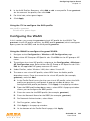
Configuring the Aruba Controller . . . . . . . . . . . . . . . . . . . . . . . . . . . .
Run the Initial Setup . . . . . . . . . . . . . . . . . . . . . . . . . . . . . . . . . . . . . .
Configure a VLAN for Network Connection . . . . . . . . . . . . . . . .
Configure the Loopback for the Controller . . . . . . . . . . . . . . . . .
Configure the System Clock . . . . . . . . . . . . . . . . . . . . . . . . . . . . . .
Install Licenses . . . . . . . . . . . . . . . . . . . . . . . . . . . . . . . . . . . . . . . . . .
Connect the Controller to the Network . . . . . . . . . . . . . . . . . . . .
Deploying APs . . . . . . . . . . . . . . . . . . . . . . . . . . . . . . . . . . . . . . . . . . . . .
Run Aruba RF Plan . . . . . . . . . . . . . . . . . . . . . . . . . . . . . . . . . . . . . . .
Enable APs to Connect to the Controller . . . . . . . . . . . . . . . . . .
Provision APs for Mesh . . . . . . . . . . . . . . . . . . . . . . . . . . . . . . . . . .
Install APs . . . . . . . . . . . . . . . . . . . . . . . . . . . . . . . . . . . . . . . . . . . . . . .
Update RF Plan . . . . . . . . . . . . . . . . . . . . . . . . . . . . . . . . . . . . . . . . . .
Additional Configuration . . . . . . . . . . . . . . . . . . . . . . . . . . . . . . . . . . . .
54
54
55
57
59
59
59
60
60
60
64
64
65
65
Chapter 3 Configuring Network Parameters
Configuring VLANs . . . . . . . . . . . . . . . . . . . . . . . . . . . . . . . . . . . . . . . . .
Configuring Ports . . . . . . . . . . . . . . . . . . . . . . . . . . . . . . . . . . . . . . . .
VLAN Assignment . . . . . . . . . . . . . . . . . . . . . . . . . . . . . . . . . . . . . . .
Assigning a Static Address to a VLAN . . . . . . . . . . . . . . . . . . . . .
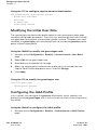
Configuring a VLAN to Receive a Dynamic Address . . . . . . . .
Configuring Source NAT for VLAN Interfaces . . . . . . . . . . . . . .
Inter-VLAN Routing . . . . . . . . . . . . . . . . . . . . . . . . . . . . . . . . . . . . . .
Configuring Static Routes . . . . . . . . . . . . . . . . . . . . . . . . . . . . . . . . . . .
Configuring the Loopback IP Address . . . . . . . . . . . . . . . . . . . . . . .
Configuring GRE Tunnels . . . . . . . . . . . . . . . . . . . . . . . . . . . . . . . . . . .
Creating a Tunnel Interface . . . . . . . . . . . . . . . . . . . . . . . . . . . . . . .
Directing Traffic into the Tunnel. . . . . . . . . . . . . . . . . . . . . . . . . . .
68
68
69
70
70
74
76
77
78
79
79
80
Chapter 4 RF Plan
Overview . . . . . . . . . . . . . . . . . . . . . . . . . . . . . . . . . . . . . . . . . . . . . . . . . .
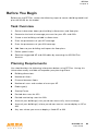
Before You Begin . . . . . . . . . . . . . . . . . . . . . . . . . . . . . . . . . . . . . . . . . . .
Task Overview . . . . . . . . . . . . . . . . . . . . . . . . . . . . . . . . . . . . . . . . . . .
Planning Requirements . . . . . . . . . . . . . . . . . . . . . . . . . . . . . . . . . . .
84
85
85
85
ArubaOS 3.2
User Guide
0510339-02
September 2007
Contents
Using RF Plan . . . . . . . . . . . . . . . . . . . . . . . . . . . . . . . . . . . . . . . . . . . . . . 86
Campus List Page . . . . . . . . . . . . . . . . . . . . . . . . . . . . . . . . . . . . . . . . 86
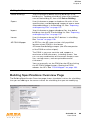
Building List Page . . . . . . . . . . . . . . . . . . . . . . . . . . . . . . . . . . . . . . . . 88
Building Specifications Overview Page . . . . . . . . . . . . . . . . . . . . 89
Building Dimension Page . . . . . . . . . . . . . . . . . . . . . . . . . . . . . . . . . 90
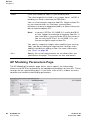
AP Modeling Parameters Page . . . . . . . . . . . . . . . . . . . . . . . . . . . . 92
AM Modeling Page . . . . . . . . . . . . . . . . . . . . . . . . . . . . . . . . . . . . . . . 95
Planning Floors Pages . . . . . . . . . . . . . . . . . . . . . . . . . . . . . . . . . . . . 97
AP Plan Page . . . . . . . . . . . . . . . . . . . . . . . . . . . . . . . . . . . . . . . . . . . 104
AM Plan Page . . . . . . . . . . . . . . . . . . . . . . . . . . . . . . . . . . . . . . . . . . 106
Exporting and Importing Files . . . . . . . . . . . . . . . . . . . . . . . . . . . . 107
Locate . . . . . . . . . . . . . . . . . . . . . . . . . . . . . . . . . . . . . . . . . . . . . . . . . . 109
FQLN Mapper . . . . . . . . . . . . . . . . . . . . . . . . . . . . . . . . . . . . . . . . . . . 109
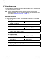
RF Plan Example . . . . . . . . . . . . . . . . . . . . . . . . . . . . . . . . . . . . . . . . . . 114
Sample Building . . . . . . . . . . . . . . . . . . . . . . . . . . . . . . . . . . . . . . . . . 114
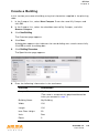
Create a Building . . . . . . . . . . . . . . . . . . . . . . . . . . . . . . . . . . . . . . . 115
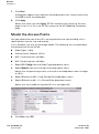
Model the Access Points . . . . . . . . . . . . . . . . . . . . . . . . . . . . . . . 116
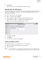
Model the Air Monitors . . . . . . . . . . . . . . . . . . . . . . . . . . . . . . . . . 117
Add and Edit a Floor . . . . . . . . . . . . . . . . . . . . . . . . . . . . . . . . . . . . 117
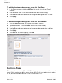
Defining Areas . . . . . . . . . . . . . . . . . . . . . . . . . . . . . . . . . . . . . . . . . . 118
Running the AP Plan . . . . . . . . . . . . . . . . . . . . . . . . . . . . . . . . . . . 121
Running the AM Plan . . . . . . . . . . . . . . . . . . . . . . . . . . . . . . . . . . . 123
Volume 3
Configuring APs
Chapter 5 Configuring Access Points
AP Configuration Overview . . . . . . . . . . . . . . . . . . . . . . . . . . . . . . . .
AP Names and Groups . . . . . . . . . . . . . . . . . . . . . . . . . . . . . . . . . .
Virtual APs . . . . . . . . . . . . . . . . . . . . . . . . . . . . . . . . . . . . . . . . . . . . .
Configuring Profiles . . . . . . . . . . . . . . . . . . . . . . . . . . . . . . . . . . . . . . .
Example Configurations . . . . . . . . . . . . . . . . . . . . . . . . . . . . . . . . . . .
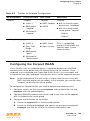
Configuring the Corpnet WLAN . . . . . . . . . . . . . . . . . . . . . . . . . .
Guest WLAN. . . . . . . . . . . . . . . . . . . . . . . . . . . . . . . . . . . . . . . . . . . .
Advanced Configuration Options . . . . . . . . . . . . . . . . . . . . . . . . . . .
Channel Switch Announcement . . . . . . . . . . . . . . . . . . . . . . . . .
Deploying APs Over Low-Speed Links . . . . . . . . . . . . . . . . . . .
AP Redundancy . . . . . . . . . . . . . . . . . . . . . . . . . . . . . . . . . . . . . . . . .
ArubaOS 3.2
User Guide
128
129
132
133
138
139
144
147
147
147
149
5
Contents
6
Chapter 6 Configuring Secure Enterprise Mesh
Overview . . . . . . . . . . . . . . . . . . . . . . . . . . . . . . . . . . . . . . . . . . . . . . . . .
Aruba Controllers . . . . . . . . . . . . . . . . . . . . . . . . . . . . . . . . . . . . . . .
Mesh Portal . . . . . . . . . . . . . . . . . . . . . . . . . . . . . . . . . . . . . . . . . . . .
Mesh Point . . . . . . . . . . . . . . . . . . . . . . . . . . . . . . . . . . . . . . . . . . . . .
Mesh Cluster . . . . . . . . . . . . . . . . . . . . . . . . . . . . . . . . . . . . . . . . . . .
Mesh Profiles . . . . . . . . . . . . . . . . . . . . . . . . . . . . . . . . . . . . . . . . . . .
Mesh Link . . . . . . . . . . . . . . . . . . . . . . . . . . . . . . . . . . . . . . . . . . . . . .
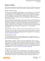
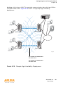
Aruba Secure Enterprise Mesh Solutions . . . . . . . . . . . . . . . . . . .
Thin AP with Wireless Backhaul Deployment . . . . . . . . . . . . .
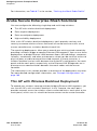
Point-to-Point Deployment . . . . . . . . . . . . . . . . . . . . . . . . . . . . . .
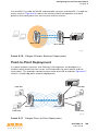
Point-to-Multipoint Deployment. . . . . . . . . . . . . . . . . . . . . . . . . .
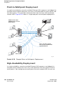
High-Availability Deployment . . . . . . . . . . . . . . . . . . . . . . . . . . . .
Before You Begin . . . . . . . . . . . . . . . . . . . . . . . . . . . . . . . . . . . . . . . . . .
Configuring APs . . . . . . . . . . . . . . . . . . . . . . . . . . . . . . . . . . . . . . . . . . .
Configuring the Mesh Profile . . . . . . . . . . . . . . . . . . . . . . . . . . . .
Configuring Ethernet Ports for Bridging . . . . . . . . . . . . . . . . . .
Provisioning APs . . . . . . . . . . . . . . . . . . . . . . . . . . . . . . . . . . . . . . . . . .
Outdoor AP Parameters . . . . . . . . . . . . . . . . . . . . . . . . . . . . . . . . .
Provisioning Caveats . . . . . . . . . . . . . . . . . . . . . . . . . . . . . . . . . . . .
Provisioning Mesh Nodes . . . . . . . . . . . . . . . . . . . . . . . . . . . . . . .
AP Boot Sequence . . . . . . . . . . . . . . . . . . . . . . . . . . . . . . . . . . . . . . . .
Mesh Portal . . . . . . . . . . . . . . . . . . . . . . . . . . . . . . . . . . . . . . . . . . . .
Mesh Point . . . . . . . . . . . . . . . . . . . . . . . . . . . . . . . . . . . . . . . . . . . . .
Air Monitoring and Mesh . . . . . . . . . . . . . . . . . . . . . . . . . . . . . . . . . .
Verifying the Network . . . . . . . . . . . . . . . . . . . . . . . . . . . . . . . . . . . . .
Example Configurations . . . . . . . . . . . . . . . . . . . . . . . . . . . . . . . . . . .
Thin AP with Wireless Backhaul Example . . . . . . . . . . . . . . . .
Ethernet LAN Example. . . . . . . . . . . . . . . . . . . . . . . . . . . . . . . . . . .
152
152
153
153
153
155
156
158
158
159
160
160
162
164
164
176
177
178
179
179
181
181
181
181
182
183
183
190
Chapter 7 Configuring Remote APs
Overview . . . . . . . . . . . . . . . . . . . . . . . . . . . . . . . . . . . . . . . . . . . . . . . . .
Configuring the Secure Remote Access Point Service . . . . . . .
Configure a Public IP Address for the Controller . . . . . . . . . .
Configure the VPN Server . . . . . . . . . . . . . . . . . . . . . . . . . . . . . . .
Configure the Remote AP User Role . . . . . . . . . . . . . . . . . . . . . .
Configure VPN Authentication . . . . . . . . . . . . . . . . . . . . . . . . . . .
Provision the AP . . . . . . . . . . . . . . . . . . . . . . . . . . . . . . . . . . . . . . . .
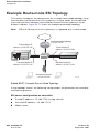
Deploying a Branch Office/Home Office Solution . . . . . . . . . . . .
Troubleshooting the Branch Office Configuration . . . . . . . . .
Double Encryption . . . . . . . . . . . . . . . . . . . . . . . . . . . . . . . . . . . . . . . . .
194
196
196
197
198
200
201
202
204
204
ArubaOS 3.2
User Guide
0510339-02
September 2007
Contents
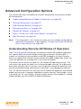
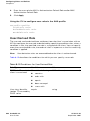
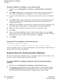
Advanced Configuration Options . . . . . . . . . . . . . . . . . . . . . . . . . . .
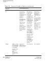
Understanding Remote AP Modes of Operation . . . . . . . . . .
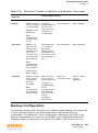
Backup Configuration . . . . . . . . . . . . . . . . . . . . . . . . . . . . . . . . . . .
DNS Controller Setting . . . . . . . . . . . . . . . . . . . . . . . . . . . . . . . . . .
Backup Controller List . . . . . . . . . . . . . . . . . . . . . . . . . . . . . . . . . . .
Remote AP Failback . . . . . . . . . . . . . . . . . . . . . . . . . . . . . . . . . . . . .
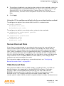
Access Control Lists and Firewall Policies . . . . . . . . . . . . . . . .
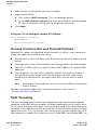
Split Tunneling . . . . . . . . . . . . . . . . . . . . . . . . . . . . . . . . . . . . . . . . . .
205
205
207
215
216
217
218
218
Volume 4
Configuring Wireless Encryption and Authentication
Chapter 8 Configuring Roles and Policies
Policies . . . . . . . . . . . . . . . . . . . . . . . . . . . . . . . . . . . . . . . . . . . . . . . . . . .
Access Control Lists (ACLs) . . . . . . . . . . . . . . . . . . . . . . . . . . . . .
Creating a Firewall Policy . . . . . . . . . . . . . . . . . . . . . . . . . . . . . . . . . .
Creating a User Role . . . . . . . . . . . . . . . . . . . . . . . . . . . . . . . . . . . . . . .
Bandwidth Contracts . . . . . . . . . . . . . . . . . . . . . . . . . . . . . . . . . . .
Assigning User Roles . . . . . . . . . . . . . . . . . . . . . . . . . . . . . . . . . . . . . .
Default User Role in AAA Profile . . . . . . . . . . . . . . . . . . . . . . . . .
User-Derived Role . . . . . . . . . . . . . . . . . . . . . . . . . . . . . . . . . . . . . . .
Default Role for Authentication Method . . . . . . . . . . . . . . . . . .
Server-Derived Role . . . . . . . . . . . . . . . . . . . . . . . . . . . . . . . . . . . . .
VSA-Derived Role . . . . . . . . . . . . . . . . . . . . . . . . . . . . . . . . . . . . . . .
Firewall Parameters . . . . . . . . . . . . . . . . . . . . . . . . . . . . . . . . . . . . . . .
230
230
231
235
237
239
239
240
242
243
243
244
Chapter 9 Configuring Authentication Servers
Servers and Server Groups . . . . . . . . . . . . . . . . . . . . . . . . . . . . . . . .
Configuring Servers . . . . . . . . . . . . . . . . . . . . . . . . . . . . . . . . . . . . . . .
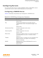
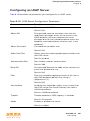
Configuring a RADIUS Server . . . . . . . . . . . . . . . . . . . . . . . . . . . .
Configuring an LDAP Server . . . . . . . . . . . . . . . . . . . . . . . . . . . . .
Configuring a TACACS+ Server . . . . . . . . . . . . . . . . . . . . . . . . . .
Configuring the Internal Database . . . . . . . . . . . . . . . . . . . . . . . .
Configuring Server Groups . . . . . . . . . . . . . . . . . . . . . . . . . . . . . . . . .
Server List Order and Fail-Through . . . . . . . . . . . . . . . . . . . . . . .
Dynamic Server Selection . . . . . . . . . . . . . . . . . . . . . . . . . . . . . . .
Trimming Domain Information from Requests . . . . . . . . . . . .
Configuring Server-Derivation Rules . . . . . . . . . . . . . . . . . . . . . .
Assigning Server Groups . . . . . . . . . . . . . . . . . . . . . . . . . . . . . . . . . .
User Authentication . . . . . . . . . . . . . . . . . . . . . . . . . . . . . . . . . . . . .
Management Authentication . . . . . . . . . . . . . . . . . . . . . . . . . . . . .
Accounting . . . . . . . . . . . . . . . . . . . . . . . . . . . . . . . . . . . . . . . . . . . . .
Configuring Authentication Timers . . . . . . . . . . . . . . . . . . . . . . . . .
248
249
249
251
252
253
255
255
257
260
261
264
264
264
265
268
ArubaOS 3.2
User Guide
7
Contents
Chapter 10 Configuring 802.1x Authentication
Overview of 802.1x Authentication . . . . . . . . . . . . . . . . . . . . . . . . .
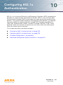
Authentication with a RADIUS Server . . . . . . . . . . . . . . . . . . . .
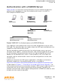
Authentication Terminated on Controller . . . . . . . . . . . . . . . . .
Configuring 802.1x Authentication . . . . . . . . . . . . . . . . . . . . . . . . .
802.1x Authentication Profile . . . . . . . . . . . . . . . . . . . . . . . . . . . .
Using Certificates with AAA FastConnect . . . . . . . . . . . . . . . .
Configuring User and Machine Authentication . . . . . . . . . . . .
Example Configurations . . . . . . . . . . . . . . . . . . . . . . . . . . . . . . . . . . .
Authentication with an 802.1x RADIUS Server . . . . . . . . . . . .
Authentication with the Controller’s Internal Database . . . .
Advanced Configuration Options for 802.1x . . . . . . . . . . . . . . . .
Reauthentication with Unicast Key Rotation . . . . . . . . . . . . . .
272
273
274
275
276
278
280
283
283
297
310
310
Chapter 11 Configuring Captive Portal
Overview of Captive Portal Functions . . . . . . . . . . . . . . . . . . . . . .
Policy Enforcement Firewall License . . . . . . . . . . . . . . . . . . . . .
Controller Server Certificate . . . . . . . . . . . . . . . . . . . . . . . . . . . . .
Configuring Captive Portal in the Base ArubaOS . . . . . . . . . . . .
314
314
314
315
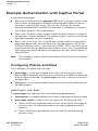
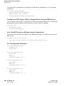
Configuring Captive Portal with the Policy Enforcement Firewall
License . . . . . . . . . . . . . . . . . . . . . . . . . . . . . . . . . . . . . . . . . . . . . . . . . . . 318
Example Authentication with Captive Portal . . . . . . . . . . . . . . . . 322
Configuring Policies and Roles . . . . . . . . . . . . . . . . . . . . . . . . . . . 322
Configuring the Guest VLAN . . . . . . . . . . . . . . . . . . . . . . . . . . . . . 330
Configuring Captive Portal Authentication . . . . . . . . . . . . . . . . 331
Modifying the Initial User Role . . . . . . . . . . . . . . . . . . . . . . . . . . . 332
Configuring the AAA Profile . . . . . . . . . . . . . . . . . . . . . . . . . . . . . 332
Configuring the WLAN . . . . . . . . . . . . . . . . . . . . . . . . . . . . . . . . . . 333
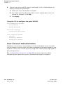
User Account Administration . . . . . . . . . . . . . . . . . . . . . . . . . . . . 334
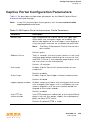
Captive Portal Configuration Parameters. . . . . . . . . . . . . . . . . . . . 335
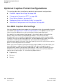
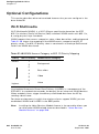
Optional Captive Portal Configurations . . . . . . . . . . . . . . . . . . . . . 338
Per-SSID Captive Portal Page . . . . . . . . . . . . . . . . . . . . . . . . . . . . 338
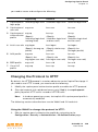
Changing the Protocol to HTTP . . . . . . . . . . . . . . . . . . . . . . . . . . 339
Proxy Server Redirect . . . . . . . . . . . . . . . . . . . . . . . . . . . . . . . . . . . 340
Redirecting Clients on Different VLANs . . . . . . . . . . . . . . . . . . . 342
Web Client Configuration with Proxy Script . . . . . . . . . . . . . . 342
Personalizing the Captive Portal Page . . . . . . . . . . . . . . . . . . . . . . 343
Chapter 12 Configuring Virtual Private Networks
VPN Configuration . . . . . . . . . . . . . . . . . . . . . . . . . . . . . . . . . . . . . . . .
Configuring Remote Access VPN for L2TP IPSec . . . . . . . . . . . .
Example Configurations . . . . . . . . . . . . . . . . . . . . . . . . . . . . . . . . .
Configuring Remote Access VPN for XAuth . . . . . . . . . . . . . . . . .
Example Configurations . . . . . . . . . . . . . . . . . . . . . . . . . . . . . . . . .
8
ArubaOS 3.2
User Guide
348
349
351
358
361
0510339-02
September 2007
Contents
Configuring Remote Access VPN for PPTP . . . . . . . . . . . . . . . . .
Configuring Site-to-Site VPNs . . . . . . . . . . . . . . . . . . . . . . . . . . . . . .
Dead Peer Detection . . . . . . . . . . . . . . . . . . . . . . . . . . . . . . . . . . . .
Configuring Aruba Dialer . . . . . . . . . . . . . . . . . . . . . . . . . . . . . . . . . . .
Captive Portal Download of Dialer . . . . . . . . . . . . . . . . . . . . . . .
367
368
371
371
372
Chapter 13 Configuring Advanced Security
Overview . . . . . . . . . . . . . . . . . . . . . . . . . . . . . . . . . . . . . . . . . . . . . . . . .
Securing Client Traffic . . . . . . . . . . . . . . . . . . . . . . . . . . . . . . . . . . . . .
Securing Wireless Clients . . . . . . . . . . . . . . . . . . . . . . . . . . . . . . .
Securing Wired Clients . . . . . . . . . . . . . . . . . . . . . . . . . . . . . . . . . .
Securing Wireless Clients Through Non-Aruba APs . . . . . . .
Securing Controller-to-Controller Communication . . . . . . . . . . .
Configuring the Odyssey Client on Client Machines . . . . . . . . .
374
375
375
378
380
382
384
Chapter 14 Configuring MAC-Based Authentication
Configuring MAC-Based Authentication . . . . . . . . . . . . . . . . . . . . 390
Configuring the MAC Authentication Profile . . . . . . . . . . . . . . 390
Configuring Clients . . . . . . . . . . . . . . . . . . . . . . . . . . . . . . . . . . . . . . . . 392
Volume 5
Configuring Multiple Controller Environments
Chapter 15 Adding Local Controllers
Moving to a Multi-Controller Environment . . . . . . . . . . . . . . . . . .
Preshared Key for Inter-Controller Communication . . . . . . . .
Configuring Local Controllers . . . . . . . . . . . . . . . . . . . . . . . . . . . . . .
Configuring the Local Controller . . . . . . . . . . . . . . . . . . . . . . . . .
Configuring Layer-2/Layer-3 Settings . . . . . . . . . . . . . . . . . . . .
Configuring Trusted Ports . . . . . . . . . . . . . . . . . . . . . . . . . . . . . . .
Configuring APs . . . . . . . . . . . . . . . . . . . . . . . . . . . . . . . . . . . . . . . .
396
396
398
398
399
400
400
Chapter 16 Configuring IP Mobility
Aruba Mobility Architecture . . . . . . . . . . . . . . . . . . . . . . . . . . . . . . . .
Configuring Mobility Domains . . . . . . . . . . . . . . . . . . . . . . . . . . . . . .
Configuring a Mobility Domain . . . . . . . . . . . . . . . . . . . . . . . . . . .
Joining a Mobility Domain . . . . . . . . . . . . . . . . . . . . . . . . . . . . . . .
Example Configuration . . . . . . . . . . . . . . . . . . . . . . . . . . . . . . . . . .
Tracking Mobile Users . . . . . . . . . . . . . . . . . . . . . . . . . . . . . . . . . . . . .
Mobile Client Roaming Status . . . . . . . . . . . . . . . . . . . . . . . . . . .
Mobile Client Roaming Locations . . . . . . . . . . . . . . . . . . . . . . . .
404
405
406
407
408
411
411
412
ArubaOS 3.2
User Guide
9
Contents
...................................
...................................
...................................
...................................
413
413
414
414
Chapter 17 Configuring Redundancy
Virtual Router Redundancy Protocol . . . . . . . . . . . . . . . . . . . . . . . .
Configuring Redundancy . . . . . . . . . . . . . . . . . . . . . . . . . . . . . . . . . . .
Configuring Local Controller Redundancy . . . . . . . . . . . . . . . .
Master Controller Redundancy . . . . . . . . . . . . . . . . . . . . . . . . . . .
Master-Local Controller Redundancy . . . . . . . . . . . . . . . . . . . . .
416
416
418
418
420
Advanced Configuration
Proxy Mobile IP . . . . . .
Proxy DHCP . . . . . . . . .
Revocations . . . . . . . . .
Volume 6
Configuring Intrusion Protection
Chapter 18 Configuring Wireless Intrusion Prevention
IDS Features . . . . . . . . . . . . . . . . . . . . . . . . . . . . . . . . . . . . . . . . . . . . . .
Unauthorized Device Detection . . . . . . . . . . . . . . . . . . . . . . . . . .
Denial of Service (DoS) Detection . . . . . . . . . . . . . . . . . . . . . . . .
Impersonation Detection . . . . . . . . . . . . . . . . . . . . . . . . . . . . . . . .
Signature Detection . . . . . . . . . . . . . . . . . . . . . . . . . . . . . . . . . . . . .
IDS Configuration . . . . . . . . . . . . . . . . . . . . . . . . . . . . . . . . . . . . . . . . .
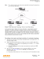
IDS Profile Hierarchy . . . . . . . . . . . . . . . . . . . . . . . . . . . . . . . . . . . .
Configuring the IDS General Profile . . . . . . . . . . . . . . . . . . . . . .
Configuring Denial of Service Attack Detection . . . . . . . . . . .
Configuring Impersonation Detection . . . . . . . . . . . . . . . . . . . .
Configuring Signature Detection . . . . . . . . . . . . . . . . . . . . . . . . .
Configuring Unauthorized Device Detection . . . . . . . . . . . . . .
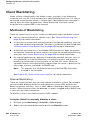
Client Blacklisting . . . . . . . . . . . . . . . . . . . . . . . . . . . . . . . . . . . . . . . . .
Methods of Blacklisting . . . . . . . . . . . . . . . . . . . . . . . . . . . . . . . . .
Blacklist Duration . . . . . . . . . . . . . . . . . . . . . . . . . . . . . . . . . . . . . . .
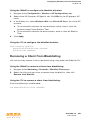
Removing a Client from Blacklisting . . . . . . . . . . . . . . . . . . . . . .
428
428
430
430
431
432
432
433
435
438
441
444
454
454
456
457
Volume 7
Managing the Aruba User-Centric Network
Chapter 19 Configuring Management Access
Management Interfaces . . . . . . . . . . . . . . . . . . . . . . . . . . . . . . . . . . . .
Web Access . . . . . . . . . . . . . . . . . . . . . . . . . . . . . . . . . . . . . . . . . . . .
CLI Access . . . . . . . . . . . . . . . . . . . . . . . . . . . . . . . . . . . . . . . . . . . . .
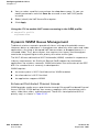
Aruba Mobility Management System . . . . . . . . . . . . . . . . . . . . .
10
ArubaOS 3.2
User Guide
462
463
468
472
0510339-02
September 2007
Contents
Configuring Management Users . . . . . . . . . . . . . . . . . . . . . . . . . . . .
Management User Roles . . . . . . . . . . . . . . . . . . . . . . . . . . . . . . . .
Management User Authentication. . . . . . . . . . . . . . . . . . . . . . . .
Configuring Management Users . . . . . . . . . . . . . . . . . . . . . . . . .
Resetting the Admin or Enable Password . . . . . . . . . . . . . . . .
Managing Certificates . . . . . . . . . . . . . . . . . . . . . . . . . . . . . . . . . . . . .
About Digital Certificates . . . . . . . . . . . . . . . . . . . . . . . . . . . . . . . .
Obtaining a Server Certificate . . . . . . . . . . . . . . . . . . . . . . . . . . . .
Obtaining a Client Certificate . . . . . . . . . . . . . . . . . . . . . . . . . . . .
Importing Certificates . . . . . . . . . . . . . . . . . . . . . . . . . . . . . . . . . . .
Viewing Certificate Information . . . . . . . . . . . . . . . . . . . . . . . . . .
Imported Certificate Locations . . . . . . . . . . . . . . . . . . . . . . . . . . .
Checking CRLs . . . . . . . . . . . . . . . . . . . . . . . . . . . . . . . . . . . . . . . . .
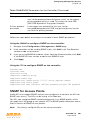
Configuring SNMP . . . . . . . . . . . . . . . . . . . . . . . . . . . . . . . . . . . . . . . .
SNMP for the Controller . . . . . . . . . . . . . . . . . . . . . . . . . . . . . . . . .
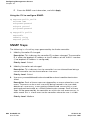
SNMP for Access Points . . . . . . . . . . . . . . . . . . . . . . . . . . . . . . . .
SNMP Traps . . . . . . . . . . . . . . . . . . . . . . . . . . . . . . . . . . . . . . . . . . . .
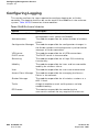
Configuring Logging . . . . . . . . . . . . . . . . . . . . . . . . . . . . . . . . . . . . . . .
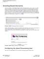
Creating Guest Accounts . . . . . . . . . . . . . . . . . . . . . . . . . . . . . . . . . .
Configuring the Guest Provisioning User . . . . . . . . . . . . . . . . .
Guest-Provisioning User Tasks . . . . . . . . . . . . . . . . . . . . . . . . . .
Optional Configurations . . . . . . . . . . . . . . . . . . . . . . . . . . . . . . . . .
Managing Files on the Controller . . . . . . . . . . . . . . . . . . . . . . . . . . .
Transferring ArubaOS Image Files . . . . . . . . . . . . . . . . . . . . . . . .
Backing Up and Restoring the Flash File System . . . . . . . . . .
Copying Log Files . . . . . . . . . . . . . . . . . . . . . . . . . . . . . . . . . . . . . . .
Copying Other Files . . . . . . . . . . . . . . . . . . . . . . . . . . . . . . . . . . . . .
Setting the System Clock . . . . . . . . . . . . . . . . . . . . . . . . . . . . . . . . . .
Manually Setting the Clock . . . . . . . . . . . . . . . . . . . . . . . . . . . . . .
Configuring an NTP Server . . . . . . . . . . . . . . . . . . . . . . . . . . . . . .
474
474
475
475
482
484
484
485
486
486
487
488
489
489
489
491
494
500
502
502
503
504
505
506
507
508
508
510
510
511
Chapter 20 Managing Software Feature Licenses
Aruba Software Licenses . . . . . . . . . . . . . . . . . . . . . . . . . . . . . . . . . .
Software License Types . . . . . . . . . . . . . . . . . . . . . . . . . . . . . . . . .
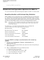
The Software Licensing Process . . . . . . . . . . . . . . . . . . . . . . . . . . .
Obtaining a Software License Certificate . . . . . . . . . . . . . . . . .
Software License Certificates . . . . . . . . . . . . . . . . . . . . . . . . . . . .
Locating the System Serial Number . . . . . . . . . . . . . . . . . . . . . .
Obtaining a Software License Key . . . . . . . . . . . . . . . . . . . . . . .
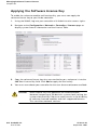
Applying the Software License Key . . . . . . . . . . . . . . . . . . . . . .
514
514
515
515
516
516
517
518
ArubaOS 3.2
User Guide
11
Contents
Additional Software License Information . . . . . . . . . . . . . . . . . . . .
Permanent Licenses . . . . . . . . . . . . . . . . . . . . . . . . . . . . . . . . . . . . .
Evaluation Licenses . . . . . . . . . . . . . . . . . . . . . . . . . . . . . . . . . . . . .
Deleting a License Key . . . . . . . . . . . . . . . . . . . . . . . . . . . . . . . . . .
Moving Licenses . . . . . . . . . . . . . . . . . . . . . . . . . . . . . . . . . . . . . . . .
Resetting the Controller . . . . . . . . . . . . . . . . . . . . . . . . . . . . . . . . .
Getting Help with Licenses . . . . . . . . . . . . . . . . . . . . . . . . . . . . . . . .
519
519
519
520
520
520
521
Volume 8
Configuring Advanced Services
12
Chapter 21 Configuring QoS for Voice
Roles and Policies for Voice Traffic . . . . . . . . . . . . . . . . . . . . . . . . .
Configuring a User Role for NOE Clients . . . . . . . . . . . . . . . . . .
Configuring a User Role for SIP Phones . . . . . . . . . . . . . . . . . .
Configuring a User Role for SVP Phones . . . . . . . . . . . . . . . . .
Configuring a User Role for Vocera Badges . . . . . . . . . . . . . . .
Configuring a User Role for SCCP Phones . . . . . . . . . . . . . . . .
Configuring a User Role for H.323 Phones. . . . . . . . . . . . . . . .
Configuring User-Derivation Rules . . . . . . . . . . . . . . . . . . . . . . .
Optional Configurations . . . . . . . . . . . . . . . . . . . . . . . . . . . . . . . . . . .
Wi-Fi Multimedia . . . . . . . . . . . . . . . . . . . . . . . . . . . . . . . . . . . . . . . .
Battery Boost . . . . . . . . . . . . . . . . . . . . . . . . . . . . . . . . . . . . . . . . . . .
WPA Fast Handover . . . . . . . . . . . . . . . . . . . . . . . . . . . . . . . . . . . . .
Voice Services Module Features . . . . . . . . . . . . . . . . . . . . . . . . . . . .
Configuring the VoIP CAC Profile . . . . . . . . . . . . . . . . . . . . . . . .
Dynamic WMM Queue Management . . . . . . . . . . . . . . . . . . . . .
TSPEC Signaling Enforcement . . . . . . . . . . . . . . . . . . . . . . . . . . .
WMM Queue Content Enforcement . . . . . . . . . . . . . . . . . . . . . .
Voice-Aware 802.1x . . . . . . . . . . . . . . . . . . . . . . . . . . . . . . . . . . . .
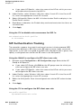
SIP Authentication Tracking . . . . . . . . . . . . . . . . . . . . . . . . . . . . .
SIP Call Setup Keepalive . . . . . . . . . . . . . . . . . . . . . . . . . . . . . . . . .
Mobile IP Home Agent Assignment . . . . . . . . . . . . . . . . . . . . . .
526
526
528
530
532
535
537
540
542
542
543
544
546
546
548
550
551
551
552
553
553
Chapter 22 External Services Interface
Understanding ESI . . . . . . . . . . . . . . . . . . . . . . . . . . . . . . . . . . . . . . . . .
Understanding the ESI Syslog Parser . . . . . . . . . . . . . . . . . . . . . . .
ESI Parser Domains . . . . . . . . . . . . . . . . . . . . . . . . . . . . . . . . . . . . .
Peer Controllers . . . . . . . . . . . . . . . . . . . . . . . . . . . . . . . . . . . . . . . . .
Syslog Parser Rules . . . . . . . . . . . . . . . . . . . . . . . . . . . . . . . . . . . . .
556
558
558
559
560
ArubaOS 3.2
User Guide
0510339-02
September 2007
Contents
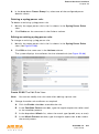
ESI Configuration Overview . . . . . . . . . . . . . . . . . . . . . . . . . . . . . . . .
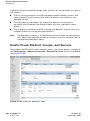
Health-Check Method, Groups, and Servers . . . . . . . . . . . . . .
Redirection Policies and User Role . . . . . . . . . . . . . . . . . . . . . . .
ESI Syslog Parser Domains and Rules . . . . . . . . . . . . . . . . . . . .
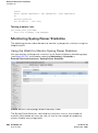
Monitoring Syslog Parser Statistics . . . . . . . . . . . . . . . . . . . . . .
Example Route-mode ESI Topology . . . . . . . . . . . . . . . . . . . . . . . . .
Configuring the Example Routed ESI Topology . . . . . . . . . . .
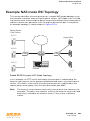
Example NAT-mode ESI Topology . . . . . . . . . . . . . . . . . . . . . . . . . .
Configuring the Example NAT-mode ESI Topology . . . . . . . .
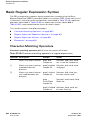
Basic Regular Expression Syntax . . . . . . . . . . . . . . . . . . . . . . . . . . .
Character-Matching Operators . . . . . . . . . . . . . . . . . . . . . . . . . . .
Regular Expression Repetition Operators . . . . . . . . . . . . . . . . .
Regular Expression Anchors . . . . . . . . . . . . . . . . . . . . . . . . . . . . .
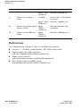
References . . . . . . . . . . . . . . . . . . . . . . . . . . . . . . . . . . . . . . . . . . . . .
561
562
566
570
580
582
583
593
594
600
600
601
601
602
Volume 9
Appendices
Appendix A Configuring DHCP with Vendor-Specific
Options . . . . . . . . . . . . . . . . . . . . . . . . . . . . . . . . . . . . 605
Overview . . . . . . . . . . . . . . . . . . . . . . . . . . . . . . . . . . . . . . . . . . . . . . . . . 606
Windows-Based DHCP Server . . . . . . . . . . . . . . . . . . . . . . . . . . . . . 606
Configuring Option 60. . . . . . . . . . . . . . . . . . . . . . . . . . . . . . . . . . . 606
Configuring Option 43. . . . . . . . . . . . . . . . . . . . . . . . . . . . . . . . . . . 607
Linux DHCP Servers . . . . . . . . . . . . . . . . . . . . . . . . . . . . . . . . . . . . . . . 609
Appendix B External Firewall Configuration . . . . . . . . . . 611
Communication Between Aruba Devices. . . . . . . . . . . . . . . . . . . . 612
Network Management Access . . . . . . . . . . . . . . . . . . . . . . . . . . . . . 613
Other Communications . . . . . . . . . . . . . . . . . . . . . . . . . . . . . . . . . . . . 614
Appendix C Aruba System Defaults . . . . . . . . . . . . . . . . . 615
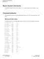
Basic System Defaults . . . . . . . . . . . . . . . . . . . . . . . . . . . . . . . . . . . . . 616
Firewall Defaults . . . . . . . . . . . . . . . . . . . . . . . . . . . . . . . . . . . . . . . . . . 616
Network Services . . . . . . . . . . . . . . . . . . . . . . . . . . . . . . . . . . . . . . . 616
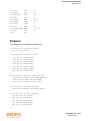
Policies . . . . . . . . . . . . . . . . . . . . . . . . . . . . . . . . . . . . . . . . . . . . . . . . . 617
System Roles . . . . . . . . . . . . . . . . . . . . . . . . . . . . . . . . . . . . . . . . . . . 618
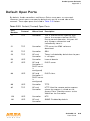
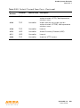
Default Open Ports . . . . . . . . . . . . . . . . . . . . . . . . . . . . . . . . . . . . . . . . 619
ArubaOS 3.2
User Guide
13
Contents
Appendix D 802.1x Configuration for IAS and Windows
Client . . . . . . . . . . . . . . . . . . . . . . . . . . . . . . . . . . . . . . 623
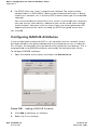
Configuring Microsoft IAS . . . . . . . . . . . . . . . . . . . . . . . . . . . . . . . . . 623
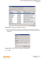
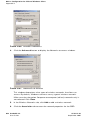
RADIUS Client Configuration . . . . . . . . . . . . . . . . . . . . . . . . . . . . 623
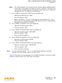
Remote Access Policies . . . . . . . . . . . . . . . . . . . . . . . . . . . . . . . . . 625
Configuring RADIUS Attributes . . . . . . . . . . . . . . . . . . . . . . . . . . 630
Window XP Wireless Client Example Configuration . . . . . . . . . 633
Appendix E Internal Captive Portal . . . . . . . . . . . . . . . . . . 639
Creating a New Internal Web Page . . . . . . . . . . . . . . . . . . . . . . . . . 640
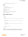
Basic HTML Example . . . . . . . . . . . . . . . . . . . . . . . . . . . . . . . . . . . . 641
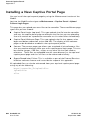
Installing a New Captive Portal Page . . . . . . . . . . . . . . . . . . . . . . . 642
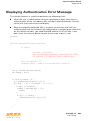
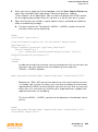
Displaying Authentication Error Message . . . . . . . . . . . . . . . . . . . 643
Reverting to the Default Captive Portal . . . . . . . . . . . . . . . . . . . . . 644
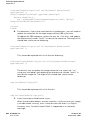
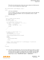
Language Customization . . . . . . . . . . . . . . . . . . . . . . . . . . . . . . . . . . . 644
Customizing the Welcome Page . . . . . . . . . . . . . . . . . . . . . . . . . . . . 650
Customizing the Pop-Up box . . . . . . . . . . . . . . . . . . . . . . . . . . . . . . . 652
Customizing the Logged Out Box . . . . . . . . . . . . . . . . . . . . . . . . . . 653
Index . . . . . . . . . . . . . . . . . . . . . . . . . . . . . . . . . . . . . . . . . . . . . . . . . . . 655
14
ArubaOS 3.2
User Guide
0510339-02
September 2007
List of Tables
Text Conventions . . . . . . . . . . . . . . . . . . . . . . . . . . . . . . . . . . . . . . . . .
Table 1-1 Optional Software Modules . . . . . . . . . . . . . . . . . . . . . . . . .
Table 1-2 Encryption Options by Authentication Method . . . . . . . . . . .
Table 5-3 Default AP Names . . . . . . . . . . . . . . . . . . . . . . . . . . . . . . . . .
Table 5-4 AP Profiles . . . . . . . . . . . . . . . . . . . . . . . . . . . . . . . . . . . . . . .
Table 5-5 Profiles for Example Configuration . . . . . . . . . . . . . . . . . . . .
Table 6-6 Mesh Link Metric Computation . . . . . . . . . . . . . . . . . . . . . . .
Table 6-7 Mesh Radio Profile Configuration Parameters . . . . . . . . . . . .
Table 6-8 Mesh Cluster Configuration Parameters . . . . . . . . . . . . . . . .
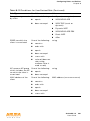
Table 7-9 Remote AP Modes of Operation and Behavior . . . . . . . . . . . .
Table 8-10 Firewall Policy Rule Parameters . . . . . . . . . . . . . . . . . . . . . .
Table 8-11 User Role Parameters . . . . . . . . . . . . . . . . . . . . . . . . . . . . .
Table 8-12 Conditions for User-Derived Role . . . . . . . . . . . . . . . . . . . . .
Table 8-13 Firewall Parameters . . . . . . . . . . . . . . . . . . . . . . . . . . . . . . .
Table 9-14 RADIUS Server Configuration Parameters . . . . . . . . . . . . . .
Table 9-15 LDAP Server Configuration Parameters . . . . . . . . . . . . . . . .
Table 9-16 TACACS+ Server Configuration Parameters . . . . . . . . . . . . .
Table 9-17 Internal Database Configuration Parameters . . . . . . . . . . . .
Table 9-18 Server Rule Configuration Parameters . . . . . . . . . . . . . . . . .
Table 9-19 Server Types and Purposes . . . . . . . . . . . . . . . . . . . . . . . . .
Table 9-20 Authentication Timers . . . . . . . . . . . . . . . . . . . . . . . . . . . . .
Table 10-21 802.1x Authentication Profile Basic WebUI Parameters . . .
Table 10-22 Role Assignment for User and Machine Authentication . . .
Table 10-23 VLAN Assignment for User and Machine Authentication . .
Table 11-24 Captive Portal Authentication Profile Parameters . . . . . . .
Table 14-25 MAC Authentication Profile Configuration Parameters . . .
Table 17-26 VRRP Parameters . . . . . . . . . . . . . . . . . . . . . . . . . . . . . . . .
Table 18-27 IDS Profiles . . . . . . . . . . . . . . . . . . . . . . . . . . . . . . . . . . . .
Table 18-28 IDS General Profile Configuration Parameters . . . . . . . . . .
Table 18-29 IDS Denial of Service Profile Configuration Parameters . . .
Table 18-30 IDS Rate Thresholds Profile Configuration Parameters . . .
Table 18-31 IDS Impersonation Profile Configuration Parameters . . . . .
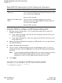
Table 18-32 Predefined Signatures . . . . . . . . . . . . . . . . . . . . . . . . . . . .
Table 18-33 Signature Rule Attributes . . . . . . . . . . . . . . . . . . . . . . . . . .
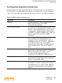
Table 18-34 IDS Unauthorized Device Profile Configuration Parameters
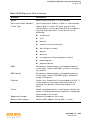
Table 18-35 WMS Configuration Parameters . . . . . . . . . . . . . . . . . . . .
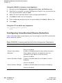
Table 18-36 Valid SSIDs with Multi-Tenancy and Misconfigured AP
Protection . . . . . . . . . . . . . . . . . . . . . . . . . . . . . . . . . . . . . . . . . . . . . . .
Table 19-37 WebUI Tools . . . . . . . . . . . . . . . . . . . . . . . . . . . . . . . . . . .
.
.
.
.
.
.
.
.
.
.
.
.
.
.
.
.
.
.
.
.
.
.
.
.
.
.
.
.
.
.
.
.
.
.
.
.
. . 22
. . 35
. . 39
. 129
. 133
. 139
. 157
. 166
. 172
. 206
. 231
. 235
. 240
. 244
. 249
. 251
. 252
. 254
. 261
. 264
. 268
. 277
. 280
. 282
. 335
. 390
. 417
. 432
. 433
. 435
. 437
. 439
. 441
. 443
. 444
. 448
. . 452
. . 466
ArubaOS 3.2
User Guide
15
List of Tables
Table
Table
Table
Table
Table
Table
Table
Table
Table
Table
Table
Table
Table
Table
16
19-38 Configuration Pages . . . . . . . . . . . . . . . . . . . . . . . . .
19-39 Line Editing Keys . . . . . . . . . . . . . . . . . . . . . . . . . . . .
19-40 SNMP Parameters for the Controller . . . . . . . . . . . . .
19-41 SNMP Profile Configuration Parameters . . . . . . . . . .
19-42 SNMP User Profile Configuration Parameters . . . . . .
19-43 Software Modules . . . . . . . . . . . . . . . . . . . . . . . . . . .
19-44 Logging Levels . . . . . . . . . . . . . . . . . . . . . . . . . . . . . .
19-45 File Transfer Configuration Parameters . . . . . . . . . . .
21-46 WMM Access Category to 802.1D Priority Mapping .
21-47 WMM Access Categories and 802.1d Tags . . . . . . . .
22-48 Character-matching operators in regular expressions
22-49 Regular expression repetition operators . . . . . . . . . . .
22-50 Regular expression anchors . . . . . . . . . . . . . . . . . . . .
C-51 Default (Trusted) Open Ports . . . . . . . . . . . . . . . . . . . .
ArubaOS 3.2
User Guide
.
.
.
.
.
.
.
.
.
.
.
.
.
.
.
.
.
.
.
.
.
.
.
.
.
.
.
.
.
.
.
.
.
.
.
.
.
.
.
.
.
.
.
.
.
.
.
.
.
.
.
.
.
.
.
.
.
.
.
.
.
.
.
.
.
.
.
.
.
.
. 467
. 470
. 489
. 492
. 492
. 500
. 501
. 506
. 542
. 549
. 600
. 601
. 601
. 619
0510339-02
September 2007
List of Figures
Figure
Figure
Figure
Figure
Figure
Figure
Figure
Figure
Figure
Figure
Figure
Figure
Figure
Figure
Figure
Figure
Figure
Figure
Figure
Figure
Figure
Figure
Figure
Figure
Figure
Figure
Figure
Figure
Figure
Figure
Figure
Figure
Figure
Figure
Figure
Figure
Figure
Figure
Figure
1-1 Connecting APs to the Aruba Controller . . . . . . . . . . . . .
1-2 Aruba APs Establish GRE Tunnels to the Controller . . . .
1-3 Client Traffic is Tunneled to the Controller . . . . . . . . . . .
1-4 Master and Local Controllers . . . . . . . . . . . . . . . . . . . . .
1-5 VLANs for Wireless Clients Configured on Controller . . .
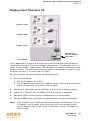
2-6 APs Connected to Controller . . . . . . . . . . . . . . . . . . . . .
3-7 IP Address Assignment to VLAN via DHCP or PPPoE . . .
3-8 Example: Source NAT using Controller IP Address . . . . .
3-9 Default Inter-VLAN Routing . . . . . . . . . . . . . . . . . . . . . . .
5-10 AP Groups . . . . . . . . . . . . . . . . . . . . . . . . . . . . . . . . . .
5-11 Virtual AP Configurations Applied to the Same AP . . . .
5-12 Applying AP Profiles to AP Groups . . . . . . . . . . . . . . .
5-13 Applying WLAN Profiles to AP Groups . . . . . . . . . . . . .
5-14 Excluding a Virtual AP Profile from an AP . . . . . . . . . . .
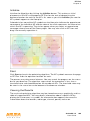
6-15 Sample Mesh Clusters . . . . . . . . . . . . . . . . . . . . . . . . .
6-16 Sample Wireless Backhaul Deployment . . . . . . . . . . . .
6-17 Sample Point-to-Point Deployment . . . . . . . . . . . . . . . .
6-18 Sample Point-to-Multipoint Deployment . . . . . . . . . . . .
6-19 Sample High-Availability Deployment . . . . . . . . . . . . . .
6-20 Displaying the Mesh Cluster Profile Settings . . . . . . . .
6-21 Configuring the Mesh Cluster Profile Settings . . . . . . .
6-22 Selecting the Mesh Radio Profile . . . . . . . . . . . . . . . . .
6-23 Configuring the Mesh Radio Profile Settings . . . . . . . .
7-24 Remote AP with a Private Network . . . . . . . . . . . . . . .
7-25 Remote AP with Controller on Public Network . . . . . . .
7-26 Remote AP with Controller Behind Firewall . . . . . . . . .
7-27 Remote AP in a Multi-Controller Environment . . . . . . .
7-28 Sample Backup Controller Scenario . . . . . . . . . . . . . . .
7-29 Sample Split Tunnel Environment . . . . . . . . . . . . . . . . .
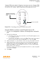
9-30 Server Group . . . . . . . . . . . . . . . . . . . . . . . . . . . . . . . .
9-31 Domain-Based Server Selection Example . . . . . . . . . . .
10-32 802.1x Authentication with RADIUS Server . . . . . . . .
10-33 802.1x Authentication with Termination on Controller
11-34 Captive Portal in Base Operating System Example . . .
12-35 Site-to-Site VPN Configuration Components . . . . . . .
13-36 Wireless xSec Client Example . . . . . . . . . . . . . . . . . . .
13-37 Wired xSec Client Example . . . . . . . . . . . . . . . . . . . . .
13-38 Controller-to-Controller xSec Example . . . . . . . . . . . .
13-39 The regedit Screen . . . . . . . . . . . . . . . . . . . . . . . . . . .
.
.
.
.
.
.
.
.
.
.
.
.
.
.
.
.
.
.
.
.
.
.
.
.
.
.
.
.
.
.
.
.
.
.
.
.
.
.
.
.
.
.
.
.
.
.
.
.
.
.
.
.
.
.
.
.
.
.
.
.
.
.
.
.
.
.
.
.
.
.
.
.
.
.
.
.
.
.
.
.
.
.
.
.
.
.
.
.
.
.
.
.
.
.
.
.
.
.
.
.
.
.
.
.
.
.
.
.
.
.
.
.
.
.
.
.
.
.
.
.
.
.
.
.
.
.
.
.
.
.
.
.
.
.
.
.
.
.
.
.
.
.
.
.
.
.
.
.
.
.
.
.
.
.
.
.
. . 29
. . 30
. . 31
. . 34
. . 41
. . 65
. . 71
. . 75
. . 76
. 130
. 132
. 136
. 136
. 137
. 154
. 159
. 159
. 160
. 161
. 186
. 186
. 188
. 188
. 194
. 195
. 195
. 195
. 216
. 219
. 248
. 258
. 273
. 274
. 316
. 368
. 376
. 378
. 382
. 384
ArubaOS 3.2
User Guide
17
List of Figures
Figure
Figure
Figure
Figure
Figure
Figure
Figure
Figure
Figure
Figure
Figure
Figure
Figure
Figure
Figure
Figure
Figure
Figure
Figure
Figure
Figure
Figure
Figure
Figure
Figure
Figure
Figure
Figure
Figure
Figure
Figure
Figure
Figure
Figure
Figure
Figure
Figure
Figure
Figure
Figure
Figure
Figure
Figure
Figure
Figure
18
13-40 Modifying a regedit Policy . . . . . . . . . . . . . . . . . . . . . . . .
13-41 The Funk Odyssey Client Profile . . . . . . . . . . . . . . . . . . . .
13-42 Certificate Information . . . . . . . . . . . . . . . . . . . . . . . . . . .
13-43 Network Profile . . . . . . . . . . . . . . . . . . . . . . . . . . . . . . . . .
16-44 Routing of Traffic to Mobile Client within Mobility Domain
16-45 Example Configuration: Campus-Wide Mobility . . . . . . . .
17-46 Redundant Topology: Master-Local Redundancy . . . . . . .
19-47 WebUI Login . . . . . . . . . . . . . . . . . . . . . . . . . . . . . . . . . . .
19-48 Creating a Guest Account . . . . . . . . . . . . . . . . . . . . . . . .
19-49 Guest Account Information . . . . . . . . . . . . . . . . . . . . . . .
19-50 Guest Provisioning Page . . . . . . . . . . . . . . . . . . . . . . . . .
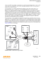
22-51 The ESI-Fortinet Topology . . . . . . . . . . . . . . . . . . . . . . . .
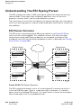
22-52 Load Balancing Groups . . . . . . . . . . . . . . . . . . . . . . . . . . .
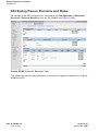
22-53 ESI Parser Domains . . . . . . . . . . . . . . . . . . . . . . . . . . . . .
22-54 Peer Controllers . . . . . . . . . . . . . . . . . . . . . . . . . . . . . . . .
22-55 External Services View . . . . . . . . . . . . . . . . . . . . . . . . . . .
22-56 User Roles View . . . . . . . . . . . . . . . . . . . . . . . . . . . . . . . .
22-57 The Add Role View . . . . . . . . . . . . . . . . . . . . . . . . . . . . . .
22-58 Firewall Polices Choices . . . . . . . . . . . . . . . . . . . . . . . . . .
22-59 Firewall Policy Attributes . . . . . . . . . . . . . . . . . . . . . . . . .
22-60 Setting Firewall Policy Parameters . . . . . . . . . . . . . . . . . .
22-61 Selecting Parameters in Drop-down Lists . . . . . . . . . . . . .
22-62 External Services View . . . . . . . . . . . . . . . . . . . . . . . . . . .
22-63 Syslog Parser Domains View . . . . . . . . . . . . . . . . . . . . . .
22-64 Add Domain View . . . . . . . . . . . . . . . . . . . . . . . . . . . . . . .
22-65 The Edit Domain View . . . . . . . . . . . . . . . . . . . . . . . . . . .
22-66 The Syslog Parser Rules View . . . . . . . . . . . . . . . . . . . . .
22-67 The New Rule View . . . . . . . . . . . . . . . . . . . . . . . . . . . . .
22-68 The Edit Rule View . . . . . . . . . . . . . . . . . . . . . . . . . . . . . .
22-69 The Syslog Parser Rule Test View . . . . . . . . . . . . . . . . . .
22-70 The Syslog Parser Statistics View . . . . . . . . . . . . . . . . . .
22-71 Example Route-Mode Topology . . . . . . . . . . . . . . . . . . . .
22-72 The User Roles View . . . . . . . . . . . . . . . . . . . . . . . . . . . . .
22-73 The Add Role View . . . . . . . . . . . . . . . . . . . . . . . . . . . . . .
22-74 Firewall Polices Choices . . . . . . . . . . . . . . . . . . . . . . . . . .
22-75 Firewall Policy Attributes . . . . . . . . . . . . . . . . . . . . . . . . .
22-76 Setting Firewall Policy Parameters . . . . . . . . . . . . . . . . . .
22-77 Selecting Parameters in Drop-down Lists . . . . . . . . . . . . .
22-78 Example NAT-Mode Topology . . . . . . . . . . . . . . . . . . . . .
A-79 Scope Options Dialog Box . . . . . . . . . . . . . . . . . . . . . . . . .
A-80 DHCP Scope Values . . . . . . . . . . . . . . . . . . . . . . . . . . . . . .
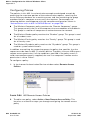
D-81 IAS RADIUS Clients . . . . . . . . . . . . . . . . . . . . . . . . . . . . . .
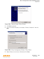
D-82 New RADIUS Client . . . . . . . . . . . . . . . . . . . . . . . . . . . . . .
D-83 RADIUS Client Shared Secret . . . . . . . . . . . . . . . . . . . . . . .
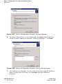
D-84 IAS Remote Access Policies . . . . . . . . . . . . . . . . . . . . . . . .
ArubaOS 3.2
User Guide
.
.
.
.
.
.
.
.
.
.
.
.
.
.
.
.
.
.
.
.
.
.
.
.
.
.
.
.
.
.
.
.
.
.
.
.
.
.
.
.
.
.
.
.
. 385
. 385
. 386
. 387
. 405
. 409
. 421
. 464
. 502
. 502
. 503
. 556
. 557
. 558
. 559
. 562
. 566
. 566
. 567
. 567
. 568
. 568
. 570
. 571
. 572
. 573
. 575
. 576
. 577
. 578
. 580
. 582
. 587
. 587
. 588
. 588
. 589
. 589
. 593
. 608
. 608
. 624
. 624
. 625
. 626
0510339-02
September 2007
List of Figures
Figure
Figure
Figure
Figure
Figure
Figure
Figure
Figure
Figure
Figure
Figure
Figure
Figure
Figure
Figure
Figure
Figure
D-85 Remote Access Policy Wizard . . . . . . . . . . . . . . . . . . .
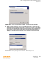
D-86 Policy Configuration Wizard - Policy Name . . . . . . . . .
D-87 Policy Configuration Wizard - Access Method . . . . . . .
D-88 Policy Configuration Wizard - User or Group Access . .
D-89 Policy Configuration Wizard - Authentication Methods
D-90 Policy Configuration Wizard - PEAP Properties . . . . . .
D-91 Adding a RADIUS Attribute . . . . . . . . . . . . . . . . . . . . .
D-92 Selecting a RADIUS Attribute . . . . . . . . . . . . . . . . . . . .
D-93 RADIUS Class Attribute Configuration . . . . . . . . . . . . .
D-94 Example RADIUS Class Attribute for “computer” . . . . .
D-95 Example RADIUS Class Attribute for “student” . . . . . .
D-96 Wireless Networks . . . . . . . . . . . . . . . . . . . . . . . . . . . .
D-97 Networks to Access . . . . . . . . . . . . . . . . . . . . . . . . . . .
D-98 Wireless Network Association . . . . . . . . . . . . . . . . . . .
D-99 Wireless Network Authentication . . . . . . . . . . . . . . . . .
D-100 Protected EAP Properties . . . . . . . . . . . . . . . . . . . . . .
D-101 EAP MSCHAPv2 Properties . . . . . . . . . . . . . . . . . . . .
.
.
.
.
.
.
.
.
.
.
.
.
.
.
.
.
.
.
.
.
.
.
.
.
.
.
.
.
.
.
.
.
.
.
.
.
.
.
.
.
.
.
.
.
.
.
.
.
.
.
.
.
.
.
.
.
.
.
.
.
.
.
.
.
.
.
.
.
. 627
. 627
. 628
. 628
. 629
. 629
. 630
. 631
. 631
. 632
. 633
. 634
. 634
. 636
. 637
. 638
. 638
ArubaOS 3.2
User Guide
19
List of Figures
20
ArubaOS 3.2
User Guide
0510339-02
September 2007
Preface
This preface includes the following information:
An overview of the contents of this manual
A list of related documentation for further reading
A key to the various text conventions used throughout this manual
Aruba Networks, Inc. support and service information
Document Organization
This user guide includes instructions and examples for commonly-used wireless
LAN (WLAN) Mobility Controller configurations such as Virtual Private Networks
(VPNs), authentication, and redundancy.
Volume 1 contains an overview of the Aruba user-centric network. Volume 2
describes how to install the Aruba user-centric network. Volume 3 describes how
to configure Aruba access points (APs), including remote APs. The remaining
volumes of the user guide describe other features of the Aruba user-centric
network.
Related Documents
The following items are part of the complete documentation for the Aruba
user-centric network:
Aruba Controller Installation Guides
Aruba Access Point Installation Guides
Release Notes
ArubaOS 3.2
User Guide
21
Preface
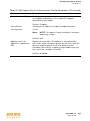
Text Conventions
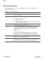
The following conventions are used throughout this manual to emphasize
important concepts:
TABLE 1
Text Conventions
Type Style
Description
Italics
This style is used to emphasize important terms and to mark
the titles of books.
System items
This fixed-width font depicts the following:
Sample screen output
System prompts
Filenames, software devices, and specific commands
when mentioned in the text
Commands
In the command examples, this bold font depicts text that
you must type exactly as shown.
<Arguments>
In the command examples, italicized text within angle
brackets represents items that you should replace with
information appropriate to your specific situation. For
example:
# send <text message>
In this example, you would type “send” at the system
prompt exactly as shown, followed by the text of the
message you wish to send. Do not type the angle brackets.
22
[ Optional ]
In the command examples, items enclosed in brackets are
optional. Do not type the brackets.
{ Item A | Item B }
In the command examples, items within curled braces and
separated by a vertical bar represent the available choices.
Enter only one choice. Do not type the braces or bars.
ArubaOS 3.2
User Guide
0510339-02
September 2007
Preface
Contacting Aruba Networks
Web Site
Main Site
http://www.arubanetworks.com
Support Site
http://www.arubanetworks.com/support
Software Licensing Site
https://licensing.arubanetworks.com
Wireless Security Incident
Response Team (WSIRT)
http://www.arubanetworks.com/support
/wsirt
Support Email
[email protected]
WSIRT Email
[email protected]
Please email details of any security
problem found in an Aruba product.
Telephone Numbers
Aruba Corporate
+1 (408) 227-4500
FAX
+1 (408) 227-4550
Support
z
United States
800-WI-FI-LAN (800-943-4526)
z
France
+33 (0) 1 70 72 55 59
z
United Kingdom
+44 (0) 20 7127 5989
z
Germany
+49 (0) 69 38 09 77 22 8
z
All other countries
+1 (408) 754-1200
ArubaOS 3.2
User Guide
23
Preface
24
ArubaOS 3.2
User Guide
0510339-02
September 2007
Volume 1
Introducing the
Aruba User-Centric
Network
ArubaOS Version 3.2
0510339-02
September 2007
26
ArubaOS 3.2
User Guide
0510339-02
September 2007
1
Overview of the Aruba
User-Centric Network
Wireless local area networks (WLANs) allow users of personal computers with
wireless network interface adapters to communicate with each other and connect
to existing wired networks. The Aruba user-centric network allows you to
implement WLANs in enterprise environments with lower cost of deployment,
simplified management, and multiple layers of security.
This chapter describes the components and features of the Aruba user-centric
network, in the following topics:
“Aruba User-Centric Network Components” on page 28
“Basic WLAN Configuration” on page 37
“Wireless Client Access to the WLAN” on page 43
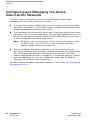
“Configuring and Managing the Aruba User-Centric Network” on page 46
ArubaOS 3.2
User Guide
27
Overview of the Aruba User-Centric Network
Chapter 1
Aruba User-Centric Network Components
The Aruba user-centric network consists of the following components:
Aruba access points
Aruba controllers
ArubaOS
The following sections describe each of these components.
Aruba Access Points
Aruba access points (APs) operate exclusively with Aruba controllers to provide
network access for wireless clients. Aruba APs support Institute of Electrical and
Electronics Engineers (IEEE) 802.11a/b/g standards for wireless systems.
NOTE:
Aruba Networks offers a range of APs that support various antenna
types and radio specifications. Refer to the Installation Guide for your
Aruba AP for specific information about supported features.
An AP broadcasts its configured service set identifier (SSID), which corresponds
to a specific wireless local area network (WLAN). Wireless clients discover APs by
listening for broadcast beacons or by sending active probes to search for APs
with a specific SSID.
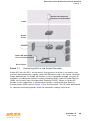
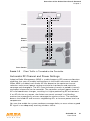
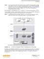
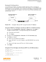
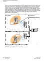
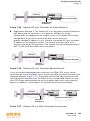
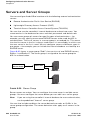
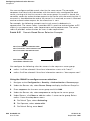
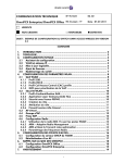
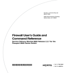
You can connect an Aruba AP to an Aruba controller either directly with an
Ethernet cable or remotely through an IP network. Figure 1-1 shows two Aruba
APs connected to an Aruba controller. One AP is connected to a switch in the
wiring closet that is connected to a router in the data center where the controller
is located. The Ethernet port on the other AP is cabled directly to a port on the
controller.
28
ArubaOS 3.2
User Guide
0510339-02
September 2007
Overview of the Aruba User-Centric Network
Chapter 1
ARUBA AP CONNECTED
THROUGH AN IP NETWORK
FLOOR
WIRING
CLOSET
INTERNET
ARUBA AP CONNECTED
WITH AN ETHERNET CABLE
ARUBA CONTROLLER
DATA CENTER
FIGURE 1-1
Connecting APs to the Aruba Controller
Aruba APs are thin APs, which means their primary function is to receive and
transmit electromagnetic signals; other WLAN processing is left to the controller.
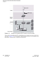
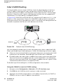
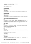
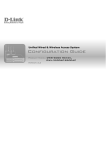
When powered on, an Aruba AP locates its host controller through a variety of
methods, including the Aruba Discovery Protocol (ADP), Domain Name Service
(DNS), or Dynamic Host Configuration Protocol (DHCP). When an Aruba AP
locates its host controller, it automatically builds a secure Generic Routing
Encapsulation (GRE) tunnel (Figure 1-2) to the controller. The AP then downloads
its software and configuration from the controller through the tunnel.
ArubaOS 3.2
User Guide
29
Overview of the Aruba User-Centric Network
Chapter 1
ARUBA AP
FLOOR
GRE TUNNEL
WIRING
CLOSET
INTERNET
GRE TUNNEL
ARUBA CONTROLLER
DATA CENTER
FIGURE 1-2
Aruba APs Establish GRE Tunnels to the Controller
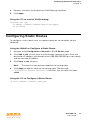
Client traffic received by the AP is immediately sent through the tunnel to the host
controller (Figure 1-3), which performs packet processing such as encryption and
decryption, authentication, and policy enforcement.
30
ArubaOS 3.2
User Guide
0510339-02
September 2007
Overview of the Aruba User-Centric Network
Chapter 1
WIRELESS CLIENTS
ARUBA AP
FLOOR
WIRING
CLOSET
INTERNET
ARUBA CONTROLLER
DATA CENTER
FIGURE 1-3
Client Traffic is Tunneled to the Controller
Automatic RF Channel and Power Settings
Adaptive Radio Management (ARM) is a radio frequency (RF) resource allocation
algorithm that you can enable and configure in the Aruba user-centric network.
When ARM is enabled, each Aruba AP can determine the optimum channel
selection and transmit power setting to minimize interference and maximize
coverage and throughput. The APs scan for better channels at periodic intervals
and report information to the controller. The controller analyzes reports from all
APs and coordinates changes, resulting in a higher performing RF environment.
If an AP fails for any reason, the Aruba user-centric network’s self-healing
mechanism automatically ensures coverage for wireless clients. The controller
detects the failed AP and instructs neighboring APs to increase power levels to
compensate.
You can also enable the system to detect coverage holes, or areas where a good
RF signal is not adequately reaching wireless clients.
ArubaOS 3.2
User Guide
31
Overview of the Aruba User-Centric Network
Chapter 1
RF Monitoring
An Aruba AP can function as either a dedicated or shared Air Monitor (AM) to
monitor radio frequency (RF) spectrums to detect intrusions, denial of service
(DoS) attacks, and other vulnerabilities. A dedicated AM performs monitoring
functions exclusively and does not service wireless clients or advertise SSIDs. A
shared AM performs monitoring functions in addition to servicing wireless
clients.
Every AP automatically monitors the channel on which it services wireless clients.
You can configure the AP to perform off-channel scanning, where the AP spends
brief time intervals scanning other channels. However, the more clients an AP
services, the less time it has to perform off-channel scanning. If air monitoring
functions are critical to your network, Aruba Networks recommends that a few
APs be designated as dedicated AMs.
For example, you can configure dedicated AMs to perform the following
functions:
Detect, locate, and disable rogue APs (APs that are not authorized or
sanctioned by network administrators)
Detect and disable ad-hoc networks
Detect and disable honeypot APs
Detect wireless bridges
Capture remote packets
If air monitoring functions are only needed periodically, you can configure APs to
operate temporarily as AMs. You can also configure dedicated AMs to
automatically convert into APs if there is an AP failure or when there is high level
of traffic on the network.
Aruba Controllers
All Aruba APs are connected either directly or remotely through an IP network to
an Aruba controller. The controller is an enterprise-class switch that bridges
wireless client traffic to and from traditional wired networks and performs
high-speed Layer-2 or Layer-3 packet forwarding between Ethernet ports. While
Aruba APs provide radio services only, the controller performs upper-layer media
access control (MAC) processing, such as encryption and authentication, as well
as centralized configuration and management of SSIDs and RF characteristics for
Aruba APs. This allows you to deploy APs with little or no physical change to an
existing wired infrastructure.
Aruba controllers provide 10/100 Mbps Fast Ethernet, IEEE 802.3af-compliant
ports that can provide Power over Ethernet (PoE) to directly-connected APs.
When you connect a PoE-capable port on the controller to a PoE-compatible
device such as an Aruba AP, the port automatically detects the device and
32
ArubaOS 3.2
User Guide
0510339-02
September 2007
Overview of the Aruba User-Centric Network
Chapter 1
provides operating power through the connected Ethernet cable. This allows APs
to be installed in areas where electrical outlets are unavailable, undesirable, or not
permitted, such as in the plenum or in air handling spaces.
NOTE:
Aruba Networks offers a range of controllers that provide different port
types and traffic capacities. Refer to the Installation Guide for your Aruba
controller for specific information about supported features.
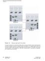
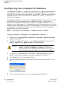
In an Aruba user-centric network, at least one controller is the master controller
while non-master controllers are referred to as local controllers (Figure 1-4). A
master controller offers a single point of configuration that is automatically
replicated from the master to local controllers throughout the network.
Local controllers offer local points of traffic aggregation and management for
Aruba APs and services. A local controller can perform any supported function
(for example, WLAN management, policy enforcement, VPN services, and so on),
however these services are always configured on the master controller and are
“pushed” to specified local controllers.
An Aruba AP obtains its software image and configuration from a master
controller; it can also be instructed by a master controller to obtain its software
from a local controller.
ArubaOS 3.2
User Guide
33
Overview of the Aruba User-Centric Network
Chapter 1
LOCAL
CONTROLLER
MASTER
CONTROLLER
LOCAL
CONTROLLER
FIGURE 1-4
Master and Local Controllers
A typical user-centric network includes one master controller, one or more backup
master controllers and any number of local controllers. It is important to note that
master controllers do not share information with each other. Thus, APs that share
roaming tables, security policies, and other configurations should be managed by
the same master controller.
34
ArubaOS 3.2
User Guide
0510339-02
September 2007
Overview of the Aruba User-Centric Network
Chapter 1
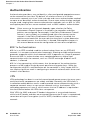
ArubaOS
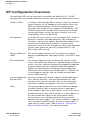
ArubaOS is a suite of mobility applications that runs on all Aruba controllers and
allows you to configure and manage the wireless and mobile user environment.
ArubaOS consists of a base software package with optional software modules
that you can activate by installing the appropriate license key (Table 1-1). The base
ArubaOS software includes the following functions:
Centralized configuration and management of APs
Wireless client authentication to an external authentication server or to the
controller’s internal database
Encryption
Mobility with fast roaming
RF management and analysis tools
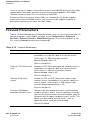
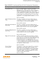
TABLE 1-1
Optional Software Modules
Optional Software Module
Description
Policy Enforcement
Firewall
Provides identity-based security for wired and
wireless clients. Stateful firewall enables
classification based on client identity, device type,
location, and time of day, and provides
differentiated access for different classes of users.
Wireless Intrusion
Protection
Detects, classifies and limits designated wireless
security threats such as rogue APs, DoS attacks,
malicious wireless attacks, impersonations, and
unauthorized intrusions. Eliminates need for
separate system of RF sensors and security
appliances.
VPN Server
Enables Aruba controllers to provide Virtual Private
Networks (VPN) tunnel termination to local and
remote clients. Provides site-to-site VPN tunnels
between Aruba controllers and third-party VPN
concentrators.
Remote AP
Allows an Aruba AP to be securely connected from
a remote location to an Aruba controller across the
Internet. Allows the remote AP to be plugged
directly into an Internet-connected DSL router; a
controller does not need to be installed at the
remote location.
Voice Services
Provides standards-based voice over WiFi features
and voice control and management.
ArubaOS 3.2
User Guide
35
Overview of the Aruba User-Centric Network
Chapter 1
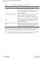
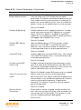
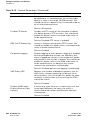
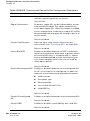
TABLE 1-1
Optional Software Modules (Continued)
Optional Software Module
Description
Ortronics AP
Enables support of the Ortronics Wi-Jack DUO
family of wall-installable wireless APs.
You can apply the license in incremental blocks up
to the maximum number of APs the given
controller supports.
Secure Enterprise Mesh
Allows an Aruba AP to be configured as a mesh
node that bridges multiple Ethernet LANs or
extends wireless coverage over wireless hops.
Licenses are available for indoor and outdoor APs.
xSec
Enables support for xSec, a Federal Information
Processing Standard (FIPS)-certifiable Layer-2
encryption protocol.
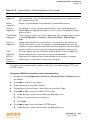
External Services Interface
(ESI)
Supports automatic redirect of clients to external
devices that provide inline network services such
as anti-virus, intrusion detection system (IDS),
content filtering, and client remediation.
Each optional module has a software license (either permanent or evaluation) that
you must install on an Aruba controller as a software license key. Contact your
sales account manager or authorized reseller to obtain software licenses.
NOTE:
36
After installing one or more software license keys, you must reboot the
Aruba controller for the new feature to become available.
ArubaOS 3.2
User Guide
0510339-02
September 2007
Overview of the Aruba User-Centric Network
Chapter 1
Basic WLAN Configuration
You have a wide variety of options for authentication, encryption, access
management, and user rights when you configure a WLAN in the Aruba
user-centric network. However, you must configure the following basic elements:
An SSID that uniquely identifies the WLAN
Layer-2 authentication to protect against unauthorized access to the WLAN
Layer-2 encryption to ensure the privacy and confidentiality of the data
transmitted to and from the network
A user role and virtual local area network (VLAN) for the authenticated client
This section describes authentication, encryption, VLAN, and user role
configuration in the Aruba user-centric network.
Authentication
A wireless client must authenticate to the Aruba user-centric network in order to
access WLAN resources. There are several types of Layer-2 security mechanisms
allowed by the IEEE 802.11 standard that you can employ in the user-centric
network, including those that require an external RADIUS authentication server:
Authentication
Method
None
Description
(Also called open system authentication) This is the default
authentication protocol. The client’s identity, in the form of the
Media Access Control (MAC) address of the wireless adapter
in the wireless client, is passed to the controller. Essentially
any client requesting access to the WLAN is authenticated.
ArubaOS 3.2
User Guide
37
Overview of the Aruba User-Centric Network
Chapter 1
Authentication
Method
IEEE 802.1x
Description
The IEEE 802.1x authentication standard allows for the use of
keys that are dynamically generated on a per-client basic (as
opposed to a static key that is the same on all devices in the
network).
NOTE:
The 802.1x standard requires the use of a RADIUS
authentication server. Most Lightweight Directory
Access Protocol (LDAP) servers do not support
802.1x.
With 802.1x authentication, a supplicant is the wireless client
that wants to gain access to the network and the device that
communicates with both the supplicant and the
authentication server is the authenticator. In the Aruba
user-centric network, the controller is the 802.1x
authenticator, relaying authentication requests between the
authentication server and the supplicant.
NOTE:
38
During the authentication process, the supplicant (the
wireless client) and the RADIUS authentication server
negotiate the type of Extensible Authentication
Protocol (EAP) they will use for the authentication
transaction. The EAP type is completely transparent
to the controller and has no impact on its
configuration.
Wi-Fi Protected
Access (WPA)
WPA implements most of the IEEE 802.11i standard. It is
designed for use with an 802.1x authentication server (the
Wi-Fi Alliance refers to this mode as WPA-Enterprise). WPA
uses the Temporal Key Integrity Protocol (TKIP) to dynamically
change keys and RC4 stream cipher to encrypt data.
WPA in
pre-shared key
(PSK) mode
(WPA-PSK)
With WPA-PSK, all clients use the same key (the Wi-Fi Alliance
refers to this mode as WPA-Personal).
WPA2
WPA2 implements the full IEEE 802.11i standard. In addition
to WPA features, WPA2 provides Counter Mode with Cipher
Blocking Chaining Message Authentication Code Protocol
(CCMP) for encryption which uses the Advanced Encryption
Standard (AES) algorithm. (The Wi-Fi Alliance refers to this
mode as WPA2-Enterprise.)
ArubaOS 3.2
User Guide
NOTE:
In PSK mode, users must enter a passphrase from
8-63 characters to access the network. PSK is
intended for home and small office networks where
operating an 802.1x authentication server is not
practical.
0510339-02
September 2007
Overview of the Aruba User-Centric Network
Chapter 1
Authentication
Method
WPA2-PSK
Description
WPA2-PSK is WPA2 used in PSK mode, where all clients use
the same key. (The Wi-Fi Alliance refers to this mode as
WPA2-Personal.)
Encryption
The Layer-2 encryption option you can select depends upon the authentication
method chosen (Table 1-2).
TABLE 1-2
Encryption Options by Authentication Method
Authentication Method
Encryption Option
None
Null or Static WEP
802.1x
Dynamic WEP
WPA or WPA-PSK only
TKIP
WPA2 or WPA2-PSK only
AES
Combination of WPA or WPA-PSK
and WPA2 or WPA2-PSK
Mixed TKIP/AES
You can configure the following data encryption options for the WLAN:
Encryption Method
Description
Null
Null means that no encryption is used and packets passing
between the wireless client and controller are in clear text.
Wired Equivalent
Protocol (WEP)
Defined by the original IEEE 802.11 standard, WEP uses
the RC4 stream cipher with 40-bit and 128-bit encryption
keys. The management and distribution of WEP keys is
performed outside of the 802.11 protocol. There are two
forms of WEP keys:
Temporal Key
Integrity Protocol
(TKIP)
Static WEP requires you to manually enter the key for
each client and on the controller.
Dynamic WEP allows the keys to be automatically
derived for each client for a specific authentication
method during the authentication process. Dynamic
WEP requires 802.1x authentication.
TKIP ensures that the encryption key is changed for every
data packet. You specify TKIP encryption for WPA and
WPA-PSK authentication.
ArubaOS 3.2
User Guide
39
Overview of the Aruba User-Centric Network
Chapter 1
Encryption Method
Description
Advanced
Encryption
Standard (AES)
AES is an encryption cipher that uses the Counter-mode
CBC-MAC (Cipher Block Chaining-Message Authentication
Code) Protocol (CCMP) mandated by the IEEE 802.11i
standard. AES-CCMP is specifically designed for IEEE
802.11 encryption and encrypts parts of the 802.11 MAC
headers as well as the data payload. You can specify
AES-CCMP encryption with WPA2 or WPA2-PSK
authentication.
Mixed
TKIP/AES-CCM
This option allows the controller to use TKIP encryption
with WPA or WPA-PSK clients and use AES encryption
with WPA2 or WPA2-PSK clients. This option allows you
to deploy the Aruba user-centric network in environments
that contain existing WLANs that use different
authentication and encryption.
xSec (Extreme
Security)
xSec is a Federal Information Processing Standard
(FIPS)-certifiable Layer-2 encryption. xSec can encrypt and
tunnel Layer-2 traffic between a controller and wired and
wireless clients, or between two Aruba controllers. To use
xSec encryption:
You must use 802.1x authentication, which means
that you must use a RADIUS authentication server.
You must install the ArubaOS xSec license in the
Aruba controller. If you are using xSec between two
Aruba controllers, you must install a license in each
device.
For encryption and tunneling of data between the
client and controller, you must install the Funk
Odyssey client that supports xSec in the wired or
wireless client.
VLAN
Each authenticated client is placed into a VLAN, which determines the client’s
DHCP server, IP address, and Layer-2 connection. While you could place all
authenticated wireless clients into a single VLAN, the Aruba user-centric network
allows you to group wireless clients into separate VLANs. This enables you to
differentiate groups of wireless clients and their access to network resources. For
example, you can place authorized employee clients into one VLAN and itinerant
clients, such as contractors or guests, into a separate VLAN.
40
ArubaOS 3.2
User Guide
0510339-02
September 2007
Overview of the Aruba User-Centric Network
Chapter 1
NOTE:
You create the VLANs for wireless clients only on the controller. You do
not need to create the VLANs anywhere else on your network. Because
wireless clients are tunneled to the controller (see Figure 1-3 on page 31)
to the rest of the network it appears as if the clients were directly
connected to the controller.
For example, in the topology shown in Figure 1-5, authenticated wireless clients
are placed on VLAN 20. You configure VLAN 20 only on the controller; you do not
need to configure VLAN 20 on any other device in the network.
NOTE:
To allow data to be routed to VLAN 20, you need to configure a static
route to VLAN 20 on an upstream router in the wired network.
VLAN 20
FLOOR
WIRING
CLOSET
INTERNET
VLAN 20
DATA CENTER
FIGURE 1-5
VLANs for Wireless Clients Configured on Controller
A client is assigned to a VLAN by one of several methods and there is an order of
precedence by which VLANs are assigned. For more information about creating
VLANs and how VLANs are assigned, see Chapter 3, “Configuring Network
Parameters.”
ArubaOS 3.2
User Guide
41
Overview of the Aruba User-Centric Network
Chapter 1
User Role
Every client in an Aruba user-centric network is associated with a user role, which
determines what a client is allowed to do, where and when it can operate, how
often it must re-authenticate, and which bandwidth contracts are applicable. User
roles can be simply defined; for example, you can define an “employee” role that
allows unrestricted access to all network resources at all times of the day and a
“guest” role that allows only HTTP access to the Internet during regular business
hours. Or you can define more granular user roles that are specific to jobs in an
enterprise environment, such as “IT staff” or “payroll”.
NOTE:
User roles and policies require the installation of a Policy Enforcement
Firewall license in the controller. See Table 1-1 on page 35 for
descriptions of optional ArubaOS software licenses.
In an Aruba user-centric network, a policy identifies a set of rules that applies to
traffic that passes through the controller. A policy can consist of firewall rules
that permit or deny traffic, quality of service (QoS) actions such as setting a data
packet to high priority, or administrative actions such as logging.
Whenever you create a user role, you specify one or more policies for the role. You
can apply policies to clients to give different treatment to clients on the same
network. The following example shows policies that might be applied for the user
roles “Employee” and “Guest”:
“Employee” User Role Policy:
“Guest” User Role Policy:
“Permit all traffic from any source to
any destination”
“Permit DHCP traffic from the client to
corporate DHCP server during business
hours”
“Permit DNS traffic from the client to a
public DNS server during business
hours”
“Permit HTTP traffic from the client to
any destination during business hours”
“Permit HTTPS traffic from the client to
any destination during business hours”
“Drop all traffic from the client to the
Internal Corporate network”
NOTE:
42
In the examples shown above, all clients should be securely
authenticated before network access is granted.
ArubaOS 3.2
User Guide
0510339-02
September 2007
Overview of the Aruba User-Centric Network
Chapter 1
A client is assigned a user role by one of several methods and there is an order or
precedence by which roles are assigned. For more information about configuring
user roles and how user roles are assigned, see Chapter 8, “Configuring Roles
and Policies.”
Wireless Client Access to the WLAN
Wireless clients communicate with the wired network and other wireless clients
through a WLAN in an Aruba user-centric network. There are two phases to the
process by which a wireless client gains access to a WLAN in an Aruba
user-centric network:
1.
Association of the radio network interface card (NIC) in the PC with an AP, as
described by the IEEE 802.11 standard. This association allows data link
(Layer-2) connectivity.
2.
Authentication of the wireless client before network access is allowed.
Association
APs send out beacons that contain the SSIDs of specific WLANs; the client can
select the network they want to join. Wireless clients can also send out probes to
locate a WLAN within range or to locate a specific SSID; APs within range of the
client respond. Along with the SSID, an AP also sends out the following
information:
Data rates supported by the WLAN. Clients can determine which WLAN to
associate with based on the supported data rate.
WLAN requirements for the client. For example, clients may need to use TKIP
for encrypting data transmitted on the WLAN.
The client determines which AP is best for connecting to the WLAN and attempts
to associate with it. It sends an association request to become a member of the
service set. During the association exchange, the client and controller negotiate
the data rate, authentication method, and other options.
NOTE:
Because an Aruba AP is a “thin” AP, all wireless traffic it receives is
immediately sent through a GRE tunnel to the controller. The controller
responds to client requests and communicates with an authentication
server on behalf of the client. Therefore, the client authentication and
association processes occur between the wireless client and the Aruba
controller.
ArubaOS 3.2
User Guide
43
Overview of the Aruba User-Centric Network
Chapter 1
Authentication
Authentication provides a way to identify a client and provide appropriate access
to the network for that client. By default, all wireless clients in an Aruba
user-centric network start in an initial user role and use an authentication method
to move to an identified, authenticated role. One or more authentication methods
may be used, ranging from secure authentication methods such as 802.1x, VPN,
and captive portal to less secure methods such as MAC address authentication.
NOTE:
Client access to the network depends upon whether the Policy
Enforcement Firewall license is installed in the controller and what
policies are configured. For example, if the Policy Enforcement Firewall
license is not installed, any authenticated client can connect to the
network. If the Policy Enforcement Firewall license is installed, the
policies associated with the user role that the client is given determine
the network access that the client is allowed. Subsequent chapters in
this manual demonstrate the configuration of user roles and policies.
802.1x Authentication
802.1x is an IEEE standard used for authenticating clients on any IEEE 802
network. It is an open authentication framework, allowing multiple authentication
protocols to operate within the framework. 802.1x operates as a Layer-2 protocol.
Successful 802.1x authentication must complete before any higher-layer
communication with the network, such as a DHCP exchange to obtain an IP
address, is allowed.
802.1x is key-generating, which means that the output of the authentication
process can be used to assign dynamic per-client encryption keys. While the
configuration of 802.1x authentication on the controller is fairly simple, 802.1x
can require significant work in configuring an external authentication server and
wireless client devices.
VPN
VPN technology has been in use for Internet-based remote access for many years
and client/server components are widely available. Generally, the VPN client is
installed on mobile devices and is used to provide secure communication with a
corporate network across a non-secure network such as the Internet. VPN
technology operates at Layer-3, which means that an IP address is required on
the client device before the VPN client can operate.
With VPN, the MAC and outer IP header information is transmitted cleartext,
while inner IP header and data are encrypted. Because the IP layer is unprotected,
some form of Layer-2 encryption (such as WEP) should be used on a wireless
network.
44
ArubaOS 3.2
User Guide
0510339-02
September 2007
Overview of the Aruba User-Centric Network
Chapter 1
Captive Portal
Captive portal allows a wireless client to authenticate using a web-based portal.
Captive portals are typically used in public access wireless hotspots or for hotel
in-room Internet access. After a client associates to the wireless network, their
device is assigned an IP address. The client must start a web browser and pass
an authentication check before access to the network is granted.
Captive portal authentication is the simplest form of authentication to use and
requires no software installation or configuration on the client. The
username/password exchange is encrypted using standard SSL encryption.
However, portal authentication does not provide any form of encryption beyond
the authentication process; to ensure privacy of client data, some form of
link-layer encryption (such as WEP or WPA-PSK) should be used when sensitive
data will be sent over the wireless network.
MAC Address Authentication
MAC address authentication is the process of examining the MAC address of an
associated device, comparing it to an internal or RADIUS database, and changing
the user role to an authenticated state. MAC address authentication is not a
secure form of authentication as the MAC address of a network interface card
(NIC) can be changed in software. MAC address authentication is useful for
devices that cannot support a more secure form of authentication, such as
barcode scanners, voice handsets, or manufacturing instrumentation sensors.
User roles mapped to MAC address authentication should be linked to restrictive
policies to permit only the minimum required communication. Whenever possible,
WEP encryption should also be employed to prevent unauthorized devices from
joining the network.
Client Mobility and AP Association
When a wireless client associates with an AP, it retains the association for as long
as possible. Generally, a wireless client only drops the association if the number
of errors in data transmission is too high or the signal strength is too weak.
When a wireless client roams from one AP to another in an Aruba user-centric
network, the controller can automatically maintain the client’s authentication and
state information; the client only changes the radio that it uses. When a client
roams between APs that are connected in the same mobility domain, the client
maintains its original IP address and existing IP sessions. The wireless client does
not require additional software to allow roaming. The user does not need to
re-enter authentication credentials when roaming.
ArubaOS 3.2
User Guide
45
Overview of the Aruba User-Centric Network
Chapter 1
Configuring and Managing the Aruba
User-Centric Network
There are several interfaces that you can use to configure and manage
components of the Aruba user-centric network:
The Web User Interface (WebUI) allows you to configure and manage Aruba
controllers. The WebUI is accessible through a standard Web browser from a
remote management console or workstation.
The command line interface (CLI) allows you to configure and manage Aruba
controllers. The CLI is accessible from a local console connected to the serial
port on the controller or through a Telnet or Secure Shell (SSH) session from a
remote management console or workstation.
NOTE:
By default, you can only access the CLI from the serial port or from
an SSH session. To use the CLI in a Telnet session, you must
explicitly enable Telnet on the controller.
The Aruba Mobility Management System is a suite of applications for
monitoring multiple master controllers and their related local controllers and
APs. Each application provides a Web-based user interface. The Aruba
Mobility Management System is available as an integrated appliance and as a
software application that runs on a dedicated system. See the Mobility
Manager User Guide for more information.
For more information about using these interfaces, see Chapter 19, “Configuring
Management Access.”
46
ArubaOS 3.2
User Guide
0510339-02
September 2007
Volume 2
Installing the Aruba
User-Centric
Network
ArubaOS Version 3.2
0510339-02
September 2007
48
ArubaOS 3.2
User Guide
0510339-02
September 2007
2
Deploying a Basic Aruba
User-Centric Network
This chapter describes how to connect an Aruba controller and Aruba APs to your
wired network. After completing the tasks described in this chapter, you can
configure the APs as described in Volume 3.
This chapter describes the following topics:
“Configuration Overview” on page 50
“Configuring the Aruba Controller” on page 54
“Deploying APs” on page 60
“Additional Configuration” on page 65
ArubaOS 3.2
User Guide
49
Deploying a Basic Aruba User-Centric Network
Chapter 2
Configuration Overview
This section describes typical deployment scenarios and the tasks you must
perform in connecting an Aruba controller and Aruba APs to your wired network.
Deployment Scenario #1
ROUTER
IS DEFAULT GATEWAY
FOR CONTROLLER AND CLIENTS
In this deployment scenario, the Aruba APs and controller are on the same
subnetwork and will use IP addresses assigned to the subnetwork. There are no
routers between the APs and the controller. APs can be physically connected
directly to the controller. The uplink port on the controller is connected to a layer-2
switch or router.
For this scenario, you must perform the following tasks:
1.
Run the Initial Setup.
z
Set the IP address of VLAN 1.
z
Set the default gateway to the IP address of the interface of the upstream
router to which you will connect the controller.
2.
Connect the uplink port on the controller to the switch or router interface. By
default, all ports on the controller are access ports and will carry traffic for a
single VLAN.
3.
Deploy APs. The APs will use the Aruba Discovery Protocol (ADP) to locate
the controller.
Configure the SSID(s) with VLAN 1 as the assigned VLAN for all users.
50
ArubaOS 3.2
User Guide
0510339-02
September 2007
Deploying a Basic Aruba User-Centric Network
Chapter 2
Deployment Scenario #2
FLOOR 3
SUBNET
FLOOR 2
SUBNET
FLOOR 1
SUBNET
CONTROLLER
IS
DEFAULT GATEWAY
FOR CLIENTS
DATA CENTER
In this deployment scenario, the Aruba APs and the controller are on different
subnetworks and the APs are on multiple subnetworks. The controller acts as a
router for the wireless subnetworks (the controller is the default gateway for the
wireless clients). The uplink port on the controller is connected to a layer-2 switch
or router; this port is an access port in VLAN 1.
For this scenario, you must perform the following tasks:
1.
Run the Initial Setup.
z
Set the IP address for VLAN 1.
z
Set the default gateway to the IP address of the interface of the upstream
router to which you will connect the controller.
2.
Connect the uplink port on the controller to the switch or router interface.
3.
Deploy APs. The APs will use DNS or DHCP to locate the controller.
4.
Configure VLANs for the wireless subnetworks on the controller.
5.
Configure SSIDs with the VLANs assigned for each wireless subnetwork.
NOTE:
Each wireless client VLAN must be configured on the controller with an
IP address. On the uplink switch or router, you must configure static
routes for each client VLAN, with the controller’s VLAN 1 IP address as
the next hop.
ArubaOS 3.2
User Guide
51
Deploying a Basic Aruba User-Centric Network
Chapter 2
Deployment Scenario #3
FLOOR 3
SUBNET
FLOOR 2
SUBNET
FLOOR 1
SUBNET
TRUNK
PORT
CARRIES CLIENT
TRAFFIC
ROUTER
IS DEFAULT
GATEWAY FOR
CONTROLLER AND
CLIENTS
DATA CENTER
In this deployment scenario, the Aruba APs and the controller are on different
subnetworks and the APs are on multiple subnetworks. There are routers
between the APs and the controller. The controller is connected to a layer-2
switch or router through a trunk port that carries traffic for all wireless client
VLANs. An upstream router functions as the default gateway for the wireless
users.
NOTE:
52
This deployment scenario does not use VLAN 1 to connect to the layer-2
switch or router through the trunk port. The Initial Setup prompts you for
the IP address and default gateway for VLAN 1; use the default values. In
later steps, you configure the appropriate VLAN to connect to the switch
or router as well as the default gateway.
ArubaOS 3.2
User Guide
0510339-02
September 2007
Deploying a Basic Aruba User-Centric Network
Chapter 2
For this scenario, you must perform the following tasks:
1.
Run the Initial Setup.
z
Use the default IP address for VLAN 1. Since VLAN 1 is not used to
connect to the layer-2 switch or router through the trunk port, you must
configure the appropriate VLAN in a later step.
z
Do not specify a default gateway (use the default “none”). In a later step,
you configure the default gateway.
2.
Create a VLAN that has the same VLAN ID as the VLAN on the switch or
router to which you will connect the controller. Add the uplink port on the
controller to this VLAN and configure the port as a trunk port.
3.
Add client VLANs to the trunk port.
4.
Configure the default gateway on the controller. This gateway is the IP
address of the router to which you will connect the controller.
5.
Configure the loopback interface for the controller.
6.
Connect the uplink port on the controller to the switch or router interface.
7.
Deploy APs. The APs will use DNS or DHCP to locate the controller.
You would then configure VLANs on the controller for the wireless client
subnetworks and configure SSIDs with the VLANs assigned for each wireless
subnetwork.
ArubaOS 3.2
User Guide
53
Deploying a Basic Aruba User-Centric Network
Chapter 2
Configuring the Aruba Controller
The tasks in deploying a basic Aruba user-centric network fall into two main
areas:
Configuring and connecting the Aruba controller to the wired network
(described in this section)
Deploying Aruba APs (described later in this section)
To connect the controller to the wired network:
1.
Run the Initial Setup to configure administrative information for the controller.
2.
(Deployment #3) Configure a VLAN to connect the controller to your network.
You do not need to perform this step if you are using VLAN 1 to connect the
controller to the wired network.
3.
(Optional) Configure a loopback address for the controller. You do not need to
perform this step if you are using the VLAN 1 IP address as the controller’s IP
address. Disable spanning tree on the controller if necessary.
4.
Configure the system clock.
5.
(Optional) Install licenses.
6.
Connect the ports on the controller to your network.
This section describes the steps in detail.
Run the Initial Setup
NOTE:
Do not connect the controller to your network when running the Initial
Setup. The factory-default controller boots up with a default IP address
and both DHCP server and spanning tree functions are enabled. Once you
have completed the Initial Setup, you can use either the CLI or WebUI for
further configuration before connecting the controller to your network.
When you connect to the controller for the first time using either a serial console
or a Web browser, the Initial Setup requires you to set the role (master or local) for
the controller and passwords for administrator and configuration access. The
Initial Setup also requires that you specify the country code for the country in
which the controller will operate; this sets the regulatory domain for the radio
frequencies that the APs use.
NOTE:
54
You cannot change the country code for controllers designated for
certain countries, such as the U.S. Improper country code assignment
can disrupt wireless transmissions. Most countries impose penalties and
sanctions for operators of wireless networks with devices set to
improper country codes.
ArubaOS 3.2
User Guide
0510339-02
September 2007
Deploying a Basic Aruba User-Centric Network
Chapter 2
The Initial Setup requires that you configure an IP address for the VLAN 1
interface, which you can use to access and configure the controller remotely via
an SSH or WebUI session. Configuring an IP address for the VLAN 1 interface
ensures that there is an IP address and default gateway assigned to the controller
upon completion of the Initial Setup.
After you complete the Initial Setup, the controller reboots using the new
configuration. (See the Aruba Quick Start Guide for information about using the
Initial Setup.) You can then connect to and configure the controller in several
ways using the administrator password you entered during the Initial Setup:
You can continue to use the connection to the serial port on the controller to
enter the command line interface (CLI). (Refer to Chapter 19, “Configuring
Management Access,” for information on how to access the CLI and enter
configuration commands.)
You can connect an Ethernet cable from a PC to an Ethernet port on the
controller. You can then use one of the following access methods:
z
Use the VLAN 1 IP address to start an SSH session where you can enter
CLI commands.
z
Enter the VLAN 1 IP address in a browser window to start the WebUI.
Configure a VLAN for Network Connection
You must follow the instructions in this section only if you need to configure a
trunk port between the Aruba controller and another layer-2 switch (shown in
“Deployment Scenario #3” on page 52).
This section shows how to use both the WebUI and CLI for the following
configurations (subsequent steps show how to use the WebUI only):
Create a VLAN on the controller and assign it an IP address.
Assign to the VLAN the port(s) that you will use to connect the controller to
the network. (For example, the uplink ports that you connect to a router are
usually Gigabit ports.) In the example configurations shown in this section, an
Aruba 2400 is connected to the network through its Gigabit Ethernet port
1/25.
Configure the port as a trunk port.
Configure a default gateway for the controller.
Create the VLAN
The following configurations create VLAN 5 and assign it the IP address
10.3.22.20/24.
ArubaOS 3.2
User Guide
55
Deploying a Basic Aruba User-Centric Network
Chapter 2
Using the WebUI to create the VLAN:
1.
Click the Configuration tab in the menu bar. Under Network, click the VLANs
option.
NOTE:
In the remainder of this manual, the instructions for reaching a
specific WebUI page are shortened to specify the sequence of tab or
page selections; for example, “Navigate to the Configuration >
Network > VLANs page.”
2.
Click Add to create a new VLAN.
3.
On the Add New VLAN screen, enter 5 for the VLAN ID and click Apply.
4.
Navigate to the Configuration > Network > IP > IP Interfaces page on the
WebUI. Click Edit for the VLAN you just added. Select Use the following IP
address. Enter the IP address and network mask of the VLAN interface. If
required, you can also configure the address of the DHCP server for the VLAN
by clicking Add.
5.
Click Apply to apply this configuration.
6.
At the top of the page, click Save Configuration.
NOTE:
In the WebUI configuration pages, clicking the Save Configuration
button saves configuration changes so they are retained after the
controller is rebooted. Clicking the Apply button saves changes to
the running configuration but the changes are not retained when the
controller is rebooted. A good practice is to use the Apply button to
save changes to the running configuration and, after ensuring that
the system operates as desired, click Save Configuration.
Using the CLI to create the VLAN:
(aruba)
User: admin
Password: *****
(aruba) >enable
Password:******
(aruba) #configure terminal
Enter Configuration commands, one per line. End with CNTL/Z
(aruba) (config) #vlan 5
(aruba) (config) #interface vlan 5
(aruba) (config-subif)#ip address 10.3.22.20 255.255.255.0
(aruba) (config-subif)#exit
(aruba) (config) #write memory
Assign and Configure the Trunk Port
The following configuration configures a Gigabit Ethernet port as trunk port.
56
ArubaOS 3.2
User Guide
0510339-02
September 2007
Deploying a Basic Aruba User-Centric Network
Chapter 2
Using the WebUI to configure the trunk port:
1.
Navigate to the Configuration > Network > Ports page on the WebUI.
2.
In the Port Selection section, click the port that will connect the controller to
the network. In this example, click port 25.
3.
For Port Mode, select Trunk.
4.
For Native VLAN, select VLAN 5 from the scrolling list, then click the <-- arrow.
5.
Click Apply.
Using the CLI to configure the trunk port:
interface gigabitethernet 1/25
switchport mode trunk
switchport trunk native vlan 5
To confirm the port assignments, use the show vlan command:
(aruba) (config) #show vlan
VLAN CONFIGURATION
-----------------VLAN
Name
Ports
----------1
Default
Fa1/0-23 Gig1/24
5
VLAN0005
Gig1/25
Configure the Default Gateway
The following configurations assign a default gateway for the controller.
Using the WebUI to configure the default gateway:
1.
Navigate to the Configuration > Network > IP > IP Routes page.
2.
In the Default Gateway field, enter 10.3.22.1.
3.
Click Apply.
Using the CLI to configure the default gateway:
ip default-gateway 10.3.22.1
Configure the Loopback for the Controller
You must configure a loopback address if you are not using VLAN 1 to connect
the controller to the network (see “Deployment Scenario #3” on page 52).
ArubaOS 3.2
User Guide
57
Deploying a Basic Aruba User-Centric Network
Chapter 2
If configured, the loopback address is used as the controller’s IP address. If you
do not configure a loopback address for the controller, the IP address assigned to
VLAN 1 is used as the controller’s IP address.
NOTE:
After you configure or modify a loopback address, you must reboot the
controller.
ArubaOS allows the loopback address to be part of the IP address space assigned
to a VLAN interface. In the example topology, the VLAN 5 interface on the
controller was previously configured with the IP address 10.3.22.20/24. The
loopback IP address in this example will be 10.3.22.220.
NOTE:
You configure the loopback address as a host address with a 32-bit
netmask. The loopback address should be routable from all external
networks.
Spanning tree protocol (STP) is enabled by default on the controller. STP ensures
a single active path between any two network nodes, thus avoiding bridge loops.
Disable STP on the controller if you are not employing STP in your network.
Using the WebUI to configure the loopback:
1.
Navigate to the Configuration > Network > Controller > System Settings
page.
2.
Enter the IP address under Loopback Interface.
3.
On this page, you can also turn off spanning tree. Click No for Spanning Tree
Enabled.
4.
Click Apply at the bottom of the page (you might need to scroll down the
page).
5.
At the top of the page, click Save Configuration.
You must reboot the controller for the new IP address to take effect.
6.
Navigate to the Maintenance > Controller > Reboot Controller page.
7.
Click Continue.
Using the CLI to configure the loopback:
interface loopback ip address 10.3.22.220
no spanning-tree
write memory
reload
The controller returns the following messages:
Do you really want to reset the system(y/n):
Enter y to reboot the controller or n to cancel.
58
ArubaOS 3.2
User Guide
0510339-02
September 2007
Deploying a Basic Aruba User-Centric Network
Chapter 2
System will now restart!
...
Restarting system.
To verify that the controller is accessible on the network, ping the loopback
address from a workstation on the network.
Configure the System Clock
You can manually set the clock on the controller, or configure the controller to use
a Network Time Protocol (NTP) server to synchronize its system clock with a
central time source. For more information about setting the controller’s clock, see
“Setting the System Clock” on page 510.
Install Licenses
ArubaOS consists of a base operating system with optional software modules
that you can activate by installing license keys. For more information about
obtaining and installing licenses, see “Managing Software Feature Licenses” on
page 513.
NOTE:
After you install a license, you must reboot the controller for the license
feature to become available.
Connect the Controller to the Network
Connect the ports on the controller to the appropriately-configured ports on an L2
switch or router. Make sure that you have the correct cables and that the port
LEDs indicate proper connections. Refer to the Installation Guide for the Aruba
controller for port LED and cable descriptions.
NOTE:
In many deployment scenarios, an external firewall is situated between
various Aruba devices. Appendix B, “External Firewall Configuration”
describes the network ports that must be configured on the external
firewall to allow proper operation of the Aruba network.
To verify that the controller is accessible on the network:
If you are using VLAN 1 to connect the controller to the network
(“Deployment Scenario #1” on page 50 and “Deployment Scenario #2” on
page 51), ping the VLAN 1 IP address from a workstation on the network.
If you created and configured a new VLAN (“Deployment Scenario #3” on
page 52), ping the IP address of the new VLAN from a workstation on the
network.
ArubaOS 3.2
User Guide
59
Deploying a Basic Aruba User-Centric Network
Chapter 2
Deploying APs
Aruba APs and AMs are designed to require only minimal setup to make them
operational in an Aruba user-centric network. Once APs have established
communication with the controller, you can apply advanced configuration to
individual APs or groups of APs in the network using the WebUI on the controller.
You can deploy APs by doing the following steps:
1.
Run the Java-based RF Plan tool to help position APs and import floorplans
for your installation.
2.
Ensure that the APs can locate the controller when they are connected to the
network. There are several ways in which APs can locate the controller.
3.
Define the mesh cluster profile, mesh radio profile, and provision the AP as a
mesh portal or mesh point when deploying APs in a mesh networking
environment.
NOTE:
This step is required only if you are configuring mesh.
4.
Install the APs by connecting the AP to an Ethernet port. If power over
Ethernet (PoE) is not used, connect the AP to a power source.
5.
On the controller, configure the APs.
This section describes the steps.
Run Aruba RF Plan
The Java-based RF Plan tool is an application that allows you to determine AP
placement based on your specified coverage and capacity requirements without
impacting the live network. For more information about using RF Plan, see the RF
Plan Installation and User Guide.
Enable APs to Connect to the Controller
Before you install APs in a network environment, you must ensure that the APs
will be able to locate and connect to the controller when powered on. Specifically,
you must ensure the following:
When connected to the network, each AP is assigned a valid IP address
APs are able to locate the controller
NOTE:
60
Aruba APs use Trivial File Transfer Protocol (TFTP) the first time they boot
to obtain their software image and configuration from the controller. After
the initial boot, the APs use FTP to obtain software images and
configurations from the controller.
ArubaOS 3.2
User Guide
0510339-02
September 2007
Deploying a Basic Aruba User-Centric Network
Chapter 2
In many deployment scenarios, an external firewall is situated between
various Aruba devices. Appendix B, “External Firewall Configuration”
describes the network ports that must be configured on the external
firewall to allow proper operation of the Aruba network.
Enable APs to Obtain IP Addresses
Each Aruba AP requires a unique IP address on a subnetwork that has
connectivity to a controller. Aruba recommends using the Dynamic Host
Configuration Protocol (DHCP) to provide IP addresses for APs; the DHCP server
can be an existing network server or an Aruba controller configured as a DHCP
server.
You can use an existing DHCP server in the same subnetwork as the AP to
provide the AP with its IP information. You can also configure a device in the
same subnetwork to act as a relay agent for a DHCP server on a different
subnetwork. Refer to the vendor documentation for the DHCP Server or relay
agent for information.
If an AP is on the same subnetwork as the master controller, you can configure
the controller as a DHCP server to assign an IP address to the AP. The controller
must be the only DHCP server for this subnetwork.
Using the WebUI to enable the DHCP server on the controller:
1.
Navigate to the Configuration > Network > IP > DHCP Server page.
2.
Select the Enable DHCP Server checkbox.
3.
In the Pool Configuration section, click Add.
4.
Enter information about the subnetwork for which IP addresses are to be
assigned. Click Done.
5.
If there are addresses that should not be assigned in the subnetwork:
6.
A.
Click Add in the Excluded Address Range section.
B.
Enter the address range in the Add Excluded Address section.
C.
Click Done.
Click Apply at the bottom of the page.
Using the CLI to enable the DHCP server on the controller:
ip dhcp excluded-address ipaddr ipaddr2
ip dhcp pool name
default-router ipaddr
dns-server ipaddr
domain-name name
network ipaddr mask
ArubaOS 3.2
User Guide
61
Deploying a Basic Aruba User-Centric Network
Chapter 2
Locate the Controller
An Aruba AP can discover the IP address of the controller in the following ways:
From a DNS server
From a DHCP server
Using the Aruba Discovery Protocol (ADP)
At boot time, the AP builds a list of controller IP addresses and then tries these
addresses in order until a controller is reached successfully. The list of controller
addresses is constructed as follows:
1.
If the master provisioning parameter is set to a DNS name, that name is
resolved and all resulting addresses are put on the list. If master is set to an IP
address, that address is put on the list.
2.
If the master provisioning parameter is not set and a controller address was
received in DHCP Option 43, that address is put on the list.
3.
If the master provisioning parameter is not set and no address was received
via DHCP option 43, ADP is used to discover a controller address and that
address is put on the list.
4.
Controller addresses derived from the server-name and server-ip provisioning
parameters and the default controller name aruba-master are added to the list.
NOTE:
If a DNS name resolves to multiple addresses, all addresses are
added to the list.
This list of controller IP addresses provides an enhanced redundancy scheme for
controllers that are located in multiple data centers separated across Layer-3
networks.
From a DNS Server
Aruba APs are factory-configured to use the host name aruba-master for the
master controller. For the DNS server to resolve this host name to the IP address
of the master controller, you must configure an entry on the DNS server for the
name aruba-master.
For information on how to configure a host name entry on the DNS server, refer to
the vendor documentation for your server.
NOTE:
Aruba recommends using a DNS server to provide APs with the IP
address of the master controller because it involves minimal changes to
the network and provides the greatest flexibility in the placement of APs.
When using DNS, the AP can learn multiple IP addresses to associate with a
controller. If the primary controller is unavailable or does not respond, the AP
continues through the list of learned IP addresses until it establishes a connection
with an available controller. This takes approximately 3.5 minutes per LMS.
62
ArubaOS 3.2
User Guide
0510339-02
September 2007
Deploying a Basic Aruba User-Centric Network
Chapter 2
From a DHCP Server
You can configure a DHCP server to provide the master controller’s IP address.
You must configure the DHCP server to send the controller’s IP address using the
DHCP vendor-specific attribute option 43. Aruba APs identify themselves with a
vendor class identifier set to ArubaAP in their DHCP request. When the DHCP
server responds to the request, it will send the controller’s IP address as the value
of option 43.
When using DHCP option 43, the AP accepts only one IP address. If the IP
address of the controller provided by DHCP is not available, the AP can use the
other IP addresses provisioned or learned by DNS to establish a connection.
For more information on how to configure vendor-specific information on a DHCP
server, see Appendix A, “Configuring DHCP with Vendor-Specific Options,” or
refer to the vendor documentation for your server.
Using the Aruba Discovery Protocol (ADP)
ADP is enabled by default on all Aruba APs and controllers. To use ADP, all Aruba
APs and controllers must be connected to the same Layer-2 network. If the
devices are on different networks, a Layer-3 compatible discovery mechanism,
such as DNS, DHCP, or IGMP forwarding, must be used instead.
With ADP, APs send out periodic multicast and broadcast queries to locate the
master controller. You might need to perform additional network configuration,
depending on whether the APs are in the same broadcast domain as the
controller:
If the APs are in the same broadcast domain as the master controller, the
controller automatically responds to the APs’ queries with its IP address.
If the APs are not in the same broadcast domain as the master controller, you
must enable multicast on the network (ADP multicast queries are sent to the
IP multicast group address 239.0.82.11) for the controller to respond to the
APs’ queries. You also must make sure that all routers are configured to listen
for Internet Group Management Protocol (IGMP) join requests from the
controller and can route these multicast packets.
To verify that ADP and IGMP join options are enabled on the controller, use
the following CLI command:
(WLAN_Switch) #show adp config
ADP Configuration
----------------key
value
------discovery enable
igmp-join enable
If ADP or IGMP join options are not enabled, use the following CLI
commands:
(WLAN_Switch) (config) #adp discovery enable
ArubaOS 3.2
User Guide
63
Deploying a Basic Aruba User-Centric Network
Chapter 2
(WLAN_Switch) (config) #adp igmp-join enable
Provision APs for Mesh
NOTE:
The information in this section applies only if you are configuring and
deploying APs in a mesh networking environment. If you are not, proceed
to “Install APs” on page 64.
Before you install APs in a mesh networking environment, you must do the
following:
Define and configure the mesh cluster profile and mesh radio profile before
configuring an AP to operate as a mesh node. An AP configured for mesh is
also known as a mesh node.
Provision one of the following mesh roles on the AP:
z
Mesh portal—The gateway between the wireless mesh network and the
enterprise wired LAN.
z
Mesh point—APs that can provide traditional Aruba WLAN services (such
as client connectivity, intrusion detection system (IDS) capabilities, user
roles association, LAN-to-LAN bridging, and Quality of Service (QoS) for
LAN-to-mesh communication) to clients on one radio and perform mesh
backhaul/network connectivity on the other radio. The mesh point can
also provide LAN-to-LAN bridging through their Ethernet interfaces.
NOTE:
You must install a Secure Enterprise Mesh license on any controller that
you use to provision a mesh AP. For example, if you are provisioning a
mesh node on a master controller but the mesh node will communicate
with a local controller, you must install Secure Enterprise Mesh licenses
on both the master and local controllers.
For detailed provisioning guidelines, caveats, and instructions, see Chapter 6,
“Configuring Secure Enterprise Mesh.”
Install APs
Use the AP placement map generated by RF Plan to install APs. You can either
connect the AP directly to a port on the controller, or connect the AP to another
switch or router that has layer-2 or layer-3 connectivity to the controller.
If the Ethernet port on the controller is an 802.3af Power over Ethernet (PoE) port,
the AP automatically uses it to power up. If a PoE port is not available, you must
get an AC adapter for the AP from Aruba Networks. For more information, see the
Installation Guide for the specific AP.
Once an AP is connected to the network and powered up, it attempts to locate
the master controller using one of the methods described in “Locate the
Controller” on page 62.
64
ArubaOS 3.2
User Guide
0510339-02
September 2007
Deploying a Basic Aruba User-Centric Network
Chapter 2
On the master controller, you can view the APs that have connected to the
controller in the WebUI. Navigate to the Configuration > Wireless > AP
Installation page. Figure 2-6 shows an example of this page.
FIGURE 2-6
APs Connected to Controller
Update RF Plan
After deploying APs, update the AP placement map in RF Plan. This allows more
accurate reconciliation of location tracking features provided by the Aruba
user-centric network—for example, locating users, intruders, rogue APs and other
security threats, assets, and sources of RF interference—with the physical
environment.
Additional Configuration
After you have installed a basic Aruba user-centric network, the Aruba APs
advertise the default aruba-ap SSID. Wireless users can connect to this SSID but
because you have not yet configured authentication, policies, or user roles, they
will not have access to the network. Other volumes in the ArubaOS User Guide
describe how to build upon this basic deployment to configure user roles, firewall
policies, authentication, authentication servers, and other wireless features.
Chapter 5, “Configuring Access Points,” in the ArubaOS User Guide describes
how to configure APs. The other volumes in the ArubaOS User Guide provide
more information about configuring and using features of the Aruba user-centric
network.
ArubaOS 3.2
User Guide
65
Deploying a Basic Aruba User-Centric Network
Chapter 2
66
ArubaOS 3.2
User Guide
0510339-02
September 2007
3
Configuring Network
Parameters
This chapter describes some basic network configuration on the Aruba controller.
This chapter describes the following topics:
“Configuring VLANs” on page 68
“Configuring Static Routes” on page 77
“Configuring the Loopback IP Address” on page 78
“Configuring GRE Tunnels” on page 79
ArubaOS 3.2
User Guide
67
Configuring Network Parameters
Chapter 3
Configuring VLANs
The Aruba controller operates as a layer-2 switch that uses a VLAN as a broadcast
domain. As a layer-2 switch, the controller requires an external router to route
traffic between VLANs. The controller can also operate as a layer-3 switch that
can route traffic between VLANs defined on the controller.
You can configure one or more physical ports on the controller to be members of
a VLAN. Additionally, each wireless client association constitutes a connection to
a virtual port on the controller, with membership in a specified VLAN. You can
place all authenticated wireless users into a single VLAN or into different VLANs,
depending upon your network. VLANs can exist only inside the Aruba controller
or they can extend outside the controller through 802.1q VLAN tagging.
You can optionally configure an IP address and netmask for a VLAN on the Aruba
controller. The IP address is up when at least one physical port in the VLAN is up.
The VLAN IP address can be used as a gateway by external devices; packets
directed to a VLAN IP address that are not destined for the controller are
forwarded according to the Aruba controller’s IP routing table.
Using the WebUI to create or edit a VLAN:
1.
Navigate to the Configuration > Network > VLANs page.
2.
Click Add to create a new VLAN. (To edit an existing VLAN click Edit for the
VLAN entry.)
3.
On the Add New VLAN screen, enter the VLAN ID.
4.
To add physical ports to the VLAN, click the port in the Assign this VLAN to
Ports section.
5.
Click Apply.
Using the CLI to create or edit a VLAN:
vlan <id>
interface fastethernet|gigabitethernet <slot>/<port>
switchport access vlan <id>
Configuring Ports
By default, a port carries traffic only for the VLAN to which it is assigned. You can
optionally configure a port to operate as a trunk port that can carry traffic for
multiple VLANs. A trunk port uses 802.1q tags to mark frames for specific VLANs.
For a trunk port, you specify whether the port will carry traffic for all VLANs
configured on the controller or for specific VLANs. You can also specify the native
VLAN for the port (frames on the native VLAN are not tagged).
68
ArubaOS 3.2
User Guide
0510339-02
September 2007
Configuring Network Parameters
Chapter 3
Using the WebUI to configure ports:
1.
Navigate to the Configuration > Network > Ports page.
2.
In the Port Selection section, click the port you want to configure.
3.
For Port Mode select Trunk.
4.
To specify the native VLAN, select a VLAN from the drop-down list and click
the <-- arrow.
5.
To allow the port to carry traffic for a specific set of VLANs, select Allowed
VLAN list. Select the VLAN(s) from the Allowed VLANs or Disallowed VLANs
drop-down list and click the <-- arrow.
6.
Click Apply.
Using the CLI to configure ports
interface fastethernet|gigabitethernet <slot>/<port>
switchport mode trunk
switchport trunk native vlan <id>
switchport trunk allowed vlan <id>,<id>
VLAN Assignment
A client is assigned to a VLAN by one of several methods. There is an order of
precedence by which VLANs are assigned. The assignment of VLANs are (from
lowest to highest precedence):
1.
The default VLAN is the VLAN configured for the WLAN (see “Virtual APs” on
page 132).
2.
Before client authentication, the VLAN can be derived from rules based on
client attributes (SSID, BSSID, client MAC, location, and encryption type). A
rule that derives a specific VLAN takes precedence over a rule that derives a
user role that may have a VLAN configured for it.
3.
After client authentication, the VLAN can be the VLAN configured for a default
role for an authentication method, such as 802.1x or VPN.
4.
After client authentication, the VLAN can be derived from attributes returned
by the authentication server (server-derived rule). A rule that derives a specific
VLAN takes precedence over a rule that derives a user role that may have a
VLAN configured for it.
5.
After client authentication, the VLAN can be derived from Microsoft Tunnel
attributes (Tunnel-Type, Tunnel Medium Type, and Tunnel Private Group ID).
All three attributes must be present. This does not require any server-derived
rule.
ArubaOS 3.2
User Guide
69
Configuring Network Parameters
Chapter 3
6.
After client authentication, the VLAN can be derived from Aruba Vendor
Specific Attributes (VSA) for RADIUS server authentication. This does not
require any server-derived rule.
NOTE:
If an Aruba VSA is present, it overrides any previous VLAN
assignment.
Assigning a Static Address to a VLAN
You can manually assign a static IP address to a VLAN on the controller. At least
one VLAN on the controller must be assigned a static IP address.
Using the WebUI to Assign a Static Address to a VLAN:
1.
Navigate to the Configuration > Network > IP > IP Interfaces page on the
WebUI. Click Edit for the VLAN you just added.
2.
Select the Use the following IP address option. Enter the IP address and
network mask of the VLAN interface. If required, you can also configure the
address of the DHCP server for the VLAN by clicking Add.
3.
Click Apply.
Using the CLI to Assign a Static Address to a VLAN:
interface vlan <id>
ip address <address> <netmask>
Configuring a VLAN to Receive a Dynamic
Address
A VLAN on the Aruba controller obtains its IP address in one of the following
ways:
Manually configured by the network administrator. This is the default method
and is described in “Assigning a Static Address to a VLAN” on page 70. At
least one VLAN on the controller must be assigned a static IP address.
Dynamically assigned from a Dynamic Host Configuration Protocol (DHCP) or
Point-to-Point Protocol over Ethernet (PPPoE) server. These methods are
described in the following section.
In a branch office, you can connect an Aruba controller to an uplink switch or
server that dynamically assigns IP addresses to connected devices. For example,
the controller can be connected to a DSL or cable modem, or a broadband remote
access server (BRAS). Figure 3-7 shows a branch office where an Aruba
controller connects to a cable modem. VLAN 1 has a static IP address, while
70
ArubaOS 3.2
User Guide
0510339-02
September 2007
Configuring Network Parameters
Chapter 3
VLAN 2 has a dynamic IP address assigned via DHCP or PPPoE on the uplink
device. The DHCP server on the Aruba controller assigns IP addresses to users on
the local network from a configured pool of IP addresses.
VLAN 1
VLAN 2
TO INTERNET
TO LOCAL
NETWORK
CONTROLLER
FIGURE 3-7
CABLE MODEM
OR BRAS
IP Address Assignment to VLAN via DHCP or PPPoE
To allow the controller to obtain a dynamic IP address for a VLAN:
Enable the DHCP or PPPoE client on the controller for the VLAN.
The following restrictions apply when enabling the DHCP or PPPoE client on the
controller:
You can enable the DHCP/PPPoE client on only one VLAN on the controller;
this VLAN cannot be VLAN 1.
Only one port in the VLAN can be connected to the modem or uplink switch.
At least one interface in the VLAN must be in the up state before the
DHCP/PPPoE client requests an IP address from the server.
Only one VLAN on the controller can obtain its IP address through DHCP or
PPPoE. You cannot enable both the DHCP and PPPoE client on the controller
at the same time.
Enabling the DHCP Client
The DHCP server assigns an IP address for a specified amount of time called a
lease. The controller automatically renews the lease before it expires. When you
shut down the VLAN, the DHCP lease is released.
Using the WebUI to Enable DHCP on a VLAN:
1.
Navigate to the Configuration > Network > IP > IP Interfaces page.
2.
Click Edit for a previously-created VLAN.
3.
Select Obtain an IP address from DHCP.
4.
Click Apply.
Using the CLI to Enable DHCP on a VLAN:
vlan <id>
interface vlan <id>
ArubaOS 3.2
User Guide
71
Configuring Network Parameters
Chapter 3
ip address dhcp-client
Enabling the PPPoE Client
To authenticate to the BRAS and request a dynamic IP address, the controller
must have the following configured:
PPPoE user name and password to connect to the DSL network
PPPoE service name — either an ISP name or a class of service configured on
the PPPoE server
When you shut down the VLAN, the PPPoE session terminates.
Using the WebUI to Enable the PPPoE Client on a VLAN:
1.
Navigate to the Configuration > Network > IP > IP Interfaces page.
2.
Click Edit for a previously-created VLAN.
3.
Select Obtain an IP address with PPPoE.
4.
Enter the service name, username, and password for the PPPoE session.
5.
Click Apply.
Using the CLI to Enable the PPPoE Client on a VLAN:
ip pppoe-service-name <service-name>
ip pppoe-username <name>
ip pppoe-password <password>
vlan <vlan>
interface vlan <vlan>
ip address pppoe
Default Gateway from DHCP/PPPoE
You can specify that the router IP address obtained from the DHCP or PPPoE
server be used as the default gateway for the controller.
Using the WebUI to Set a Default Gateway from DHCP/PPPoE:
1.
Navigate to the Configuration > Network > IP > IP Routes page.
2.
For Default Gateway, select (Obtain an IP address automatically).
3.
Select Apply.
Using the CLI to Set a Default Gateway from DHCP/PPPoE:
ip default-gateway import
72
ArubaOS 3.2
User Guide
0510339-02
September 2007
Configuring Network Parameters
Chapter 3
DNS/WINS Server from DHPC/PPPoE
The DHCP or PPPoE server can also provide the IP address of a DNS server or
NetBIOS name server, which can be passed to wireless clients through the
controller’s internal DHCP server.
For example, the following configures the DHCP server on the Aruba controller to
assign addresses to authenticated employees; the IP address of the DNS server
obtained by the controller via DHCP/PPPoE is provided to clients along with their
IP address.
Using the WebUI to Configure the DNS/WINS Server:
1.
Navigate to the Configuration > Network > IP > DHCP Server page.
2.
Select Enable DCHP Server.
3.
Under Pool Configuration, select Add.
4.
For Pool Name, enter employee-pool.
5.
For Default Router, enter 10.1.1.254.
6.
For DNS Servers, select Import from DHCP/PPPoE.
7.
For WINS Servers, select Import from DHCP/PPPoE.
8.
For Network, enter 10.1.1.0 for IP Address and 255.255.255.0 for Netmask.
9.
Click Done.
Using the CLI to Configure the DNS/WINS Server:
ip dhcp pool employee-pool
default-router 10.1.1.254
dns-server import
netbios-name-server import
network 10.1.1.0 255.255.255.0
Source NAT to Dynamic VLAN Address
When a VLAN interface obtains an IP address through DHCP or PPPoE, a NAT
pool (dynamic-srcnat) and a session ACL (dynamic-session-acl) are automatically
created which reference the dynamically-assigned IP addresses. This allows you
to configure policies that map private local addresses to the public address(es)
provided to the DHCP or PPPoE client. Whenever the IP address on the VLAN
changes, the dynamic NAT pool address also changes to match the new address.
For example, the following rules for a guest policy deny traffic to internal network
addresses. Traffic to other (external) destinations are source NATed to the
IP address of the DHCP/PPPoE client on the controller.
ArubaOS 3.2
User Guide
73
Configuring Network Parameters
Chapter 3
Using the WebUI to Configure Source NAT to the Dynamic VLAN:
1.
Navigate to the Configuration > Security > Access Control > Policies page.
Click Add to add the policy guest.
2.
To add a rule, click Add.
3.
4.
A.
For Source, select any.
B.
For Destination, select network and enter 10.1.0.0 for Host IP and
255.255.0.0 for Mask.
C.
For Service, select any.
D.
For Action, select reject.
E.
Click Add.
To add another rule, click Add.
A.
Leave Source, Destination, and Service as any.
B.
For Action, select src-nat.
C.
For NAT Pool, select dynamic-srcnat.
D.
Click Add.
Click Apply.
Using the CLI to Configure Source NAT to the Dynamic VLAN:
ip access-list session guest
any network 10.1.0.0 255.255.0.0 any deny
any any any src-nat pool dynamic-srcnat
Configuring Source NAT for VLAN Interfaces
The example configuration in the previous section illustrates how to configure
source NAT using a policy that is applied to a user role. You can also enable
source NAT for a VLAN interface to cause NAT to be performed on the source
address for all traffic that exits the VLAN.
Packets that exit the VLAN are given a source IP address of the “outside”
interface, which is determined by the following:
74
If you configure “private” IP addresses for the VLAN, the Aruba controller is
assumed to be the default gateway for the subnetwork. Packets that exit the
VLAN are given the IP address of the controller for their source IP address.
If the controller is forwarding the packets at Layer-3, packets that exit the
VLAN are given the IP address of the next-hop VLAN for their source IP
address.
ArubaOS 3.2
User Guide
0510339-02
September 2007
Configuring Network Parameters
Chapter 3
Example Configuration
In the following example, the Aruba controller operates within an enterprise
network. VLAN 1 is the outside VLAN. Traffic from VLAN 6 is source NATed using
the IP address of the controller. In this example, the IP address assigned to VLAN
1 is used as the controller’s IP address; thus traffic from VLAN 6 would be source
NATed to 66.1.131.5.
PRIVATE IP ADDRESSES:
192.168.2.1/24
VLAN 6
PUBLIC IP ADDRESSES:
66.1.131.5/24
VLAN 1
INSIDE
FIGURE 3-8
OUTSIDE
Example: Source NAT using Controller IP Address
Using the WebUI to Configure the Source NAT for a VLAN Interface:
1.
Navigate to the Configuration > Network > VLANs page. Click Add to
configure VLAN 6 (VLAN 1 is configured through the Initial Setup).
A.
Enter 6 for the VLAN ID.
B.
Click Apply.
2.
Navigate to the Configuration > Network > IP > IP Interfaces page.
3.
Click Edit for VLAN 6:
4.
A.
Select Use the following IP address.
B.
Enter 192.168.2.1 for the IP Address and 255.255.255.0 for the Net
Mask.
C.
Select the Enable source NAT for this VLAN checkbox.
Click Apply.
Using the CLI to Configure the Source NAT for a VLAN Interface:
interface vlan 1
ip address 66.1.131.5 255.255.255.0
interface vlan 6
ip address 192.168.2.1 255.255.255.0
ip nat inside
ip default-gateway 66.1.131.1
ArubaOS 3.2
User Guide
75
Configuring Network Parameters
Chapter 3
Inter-VLAN Routing
On the controller, you can map a VLAN to a layer-3 subnetwork by assigning a
static IP address and netmask or by configuring a DHCP or PPPoE server to
provide a dynamic IP address and netmask to the VLAN interface. The controller,
acting as a layer-3 switch, routes traffic between VLANs that are mapped to IP
subnetworks; this forwarding is enabled by default.
In Figure 3-9, VLAN 200 and VLAN 300 are assigned the IP addresses 2.1.1.1/24
and 3.1.1.1/24, respectively. Client A in VLAN 200 is able to access server B in
VLAN 300 and vice versa, provided that there is no firewall rule configured on the
controller to prevent the flow of traffic between the VLANs.
CLIENT A
FIGURE 3-9
VLAN 200
2.1.1.1/24
VLAN 300
3.1.1.1/24
SERVER B
Default Inter-VLAN Routing
You can optionally disable layer-3 traffic forwarding to or from a specified VLAN.
When you disable layer-3 forwarding on a VLAN, the following restrictions apply:
Clients on the restricted VLAN can ping each other, but cannot ping the VLAN
interface on the controller. Forwarding of inter-VLAN traffic is blocked.
IP mobility does not work when a mobile client roams to the restricted VLAN.
You must ensure that a mobile client on a restricted VLAN is not allowed to
roam to a non-restricted VLAN. For example, a mobile client on a guest VLAN
should not be able to roam to a corporate VLAN.
To disable layer-3 forwarding for a VLAN configured on the controller:
Using the WebUI to restrict VLAN routing:
76
1.
Navigate to the Configuration > Network > IP > IP Interface page.
2.
Click Edit for the VLAN for which routing is to be restricted.
3.
Configure the VLAN to either obtain an IP address dynamically (via DHCP or
PPPoE) or to use a static IP address and netmask.
ArubaOS 3.2
User Guide
0510339-02
September 2007
Configuring Network Parameters
Chapter 3
4.
Deselect (uncheck) the Enable Inter-VLAN Routing checkbox.
5.
Click Apply.
Using the CLI to restrict VLAN routing:
interface vlan <id>
ip address {<ipaddr> <netmask>|dhcp-client|pppoe}
no ip routing
Configuring Static Routes
To configure a static route (such as a default route) on the controller, do the
following:
Using the WebUI to Configure a Static Route:
1.
Navigate to the Configuration > Network > IP > IP Routes page.
2.
Click Add to add a static route to a destination network or host. Enter the
destination IP address and network mask (255.255.255.255 for a host route)
and the next hop IP address.
3.
Click Done to add the entry.
NOTE:
4.
The route has not yet been added to the routing table.
Click Apply to add this route to the routing table. The message
Configuration Updated Successfully confirms that the route has been
added.
Using the CLI to Configure a Static Route:
ip route <address> <netmask> <next_hop>
ArubaOS 3.2
User Guide
77
Configuring Network Parameters
Chapter 3
Configuring the Loopback IP Address
The loopback IP address is a logical IP interface that is used by the controller to
communicate with APs. You must configure a loopback address if you are not
using VLAN 1 to connect the controller to the network. If you do not configure a
loopback address for the controller, the IP address of VLAN 1 is used as the
controller’s IP address.
The loopback address is used as the controller’s IP address for terminating VPN
and GRE tunnels, originating requests to RADIUS servers, and accepting
administrative communications. You configure the loopback address as a host
address with a 32-bit netmask. The loopback address is not bound to any specific
interface and is operational at all times. To make use of this interface, ensure that
the IP address is reachable through one of the VLAN interfaces. It should be
routable from all external networks.
NOTE:
Any change in the controller’s IP address requires a reboot.
Using the WebUI to Configure the Loopback IP Address:
1.
Navigate to the Configuration > Network > Controller > System Settings
page on the WebUI.
2.
Modify the loopback IP address in the Loopback Interface section on this
page as required. Click Apply to apply this configuration.
CAUTION:
78
If you are using the loopback IP address to access the
WebUI, changing the loopback IP address will result in
loss of connectivity. Aruba recommends that you use one
of the VLAN interface IP addresses to access the WebUI.
3.
Navigate to the Maintenance > Controller > Reboot Controller page to
reboot the controller to apply the change of loopback IP address.
4.
Click Continue to save the configuration.
5.
When prompted that the changes were written successfully to flash, click
OK.
6.
The controller boots up with the changed loopback IP address.
ArubaOS 3.2
User Guide
0510339-02
September 2007
Configuring Network Parameters
Chapter 3
Using the CLI to Configure the Loopback IP Address:
interface loopback ip address <address>
write memory
Using the CLI to reboot the controller:
Enter the following command in Enable mode:
reload
Configuring GRE Tunnels
An Aruba controller supports generic routing encapsulation (GRE) tunnels
between the controller and APs. An AP opens a GRE tunnel to the controller for
each radio interface. On the AP, the other end of the GRE tunnel is specified by
the IP address configured variable values (in descending order of priority)
<master>, <servername>, and <serverip>. If these variable are left to default values,
the AP uses DNS to look up aruba-master to discover the IP address of the
controller.
The controller also supports GRE tunnels between the controller and other
GRE-capable devices. This section describes how to configure a GRE tunnel to
such a device and how to direct traffic into the tunnel.
NOTE:
The controller uses GRE tunnels for communications between master
and local controllers; these GRE tunnels are automatically created and are
not subject to the configuration described in this section.
Creating a Tunnel Interface
To create a GRE tunnel on the controller, you need to specify the following:
Tunnel ID: this can be a number between 1 and 2147483647.
IP address and netmask for the tunnel.
Tunnel source: the local endpoint for the tunnel on the controller. This can be
one of the following:
z
Loopback address of the controller
z
A specified IP address
z
A specified VLAN
Tunnel destination: the IP address of the remote endpoint of the tunnel on the
other GRE device.
ArubaOS 3.2
User Guide
79
Configuring Network Parameters
Chapter 3
WebUI
1.
Navigate to the Configuration > Network > IP > GRE Tunnels page.
2.
Click Add.
3.
Enter the tunnel ID.
4.
Enter the IP address and netmask for the tunnel.
5.
Select (check) Enabled to enable the tunnel interface.
6.
Select the tunnel source, if it is not the loopback address of the controller. If
you select IP Address, enter the IP address for the tunnel source. If you select
VLAN, select the ID of the VLAN.
7.
Enter the IP address of the tunnel destination.
8.
Click Apply.
CLI
interface tunnel <id>
tunnel mode gre ip
ip address <ipaddr> <netmask>
no shutdown
tunnel source {<ipaddr>| loopback | vlan <vlan>}
tunnel destination <ipaddr>
Directing Traffic into the Tunnel
You can direct traffic into the tunnel by configuring one of the following:
Static route, which redirects traffic to the IP address of the tunnel
Firewall policy (session-based ACL), which redirects traffic to the specified
tunnel ID
Static Routes
You can configure a static route that specifies the IP address of a tunnel as the
next-hop for traffic for a specific destination. See “Configuring Static Routes” on
page 77 for descriptions of how to configure a static route.
Firewall Policy
You can configure a firewall policy rule to redirect selected traffic into a tunnel.
Traffic redirected by a firewall policy rule is not forwarded to a tunnel that is
“down” (see “Tunnel Keepalives” on page 81 for more information on how GRE
tunnel status is determined). If you have more than one GRE tunnel configured,
80
ArubaOS 3.2
User Guide
0510339-02
September 2007
Configuring Network Parameters
Chapter 3
you can create multiple firewall policy rules with each rule redirecting the same
traffic to different tunnels. If the tunnel in the first traffic redirect rule is down,
then the tunnel in the subsequent traffic redirect rule is used instead.
WebUI
1.
Navigate to the Configuration > Security > Access Control > Policies page.
2.
Click Add to create a new firewall policy, or click Edit to edit a specific policy.
3.
Click Add to create a new policy rule.
4.
Configure the Source, Destination, and Service for the rule.
5.
For Action, select redirect to tunnel. Enter the tunnel ID.
6.
Configure any additional options, and click Add.
7.
Click Apply.
CLI
ip access-list session <name>
<source> <destination> <service> redirect tunnel <id>
Tunnel Keepalives
The controller can determine the status of a GRE tunnel by sending periodic
keepalive frames on the tunnel. If you enable tunnel keepalives, the tunnel is
considered to be “down” if there is repeated failure of the keepalives. If you
configured a firewall policy rule to redirect traffic to the tunnel, traffic is not
forwarded to the tunnel until it is “up”. Whenever the tunnel comes up or goes
down, an SNMP trap and a logging message are generated.
NOTE:
The remote endpoint of the tunnel does not need to support the keepalive
mechanism.
By default, the controller sends keepalive frames at 10-second intervals and
retries keepalives up to three times before the tunnel is considered to be down.
You can configure the interval (in seconds) and the number of times that the
keepalives are retried. For the interval, specify a value between 1-86400 seconds.
For the retries, specify a value between 0-1024.
WebUI
1.
Navigate to the Configuration > Network > IP > GRE Tunnels page.
2.
Click Edit for the tunnel for which you are enabling tunnel keepalives.
3.
Select (check) Enable Heartbeats to enable tunnel keepalives and display the
Heartbeat Interval and Heartbeat Retries fields.
4.
Enter values for Heartbeat Interval and Heartbeat Retries.
5.
Click Apply.
ArubaOS 3.2
User Guide
81
Configuring Network Parameters
Chapter 3
CLI
interface tunnel id
tunnel keepalive [<interval> <retries>]
82
ArubaOS 3.2
User Guide
0510339-02
September 2007
4
RF Plan
RF Plan is a wireless deployment modeling tool that enables you to design an
efficient Wireless Local Area Network (WLAN) for your corporate environment,
optimizing coverage and performance, and eliminating complicated WLAN
network setup.
This chapter describes the following topics:
“Overview” on page 84
“Before You Begin” on page 85
“Using RF Plan” on page 86
“RF Plan Example” on page 114
NOTE:
A Java-based version of the RF Plan tool allows you to input the serial
number or MAC address of each AP. For information about using the
Java-based RF Plan tool, see the RF Plan Installation and User Guide.
ArubaOS 3.2
User Guide
83
RF Plan
Chapter 4
Overview
RF Plan provides the following critical functionality:
Defines WLAN coverage.
Defines WLAN environment security coverage.
Assesses equipment requirements.
Optimizes radio resources.
RF Plan provides a view of each floor, allowing you to specify how Wi-Fi coverage
should be provided. RF Plan then provides coverage maps and AP and AM
placement locations.
Unlike other static site survey tools that require administrators to have intricate
knowledge of building materials and other potential radio frequency (RF) hazards,
RF Plan calibrates coverage in real-time through a sophisticated RF calibration
algorithm. This real-time calibration lets you characterize the indoor propagation
of RF signals to determine the best channel and transmission power settings for
each AP. You can program the calibration to occur automatically or you can
manually launch the calibration at any time to quickly adapt to changes in the
wireless environment.
84
ArubaOS 3.2
User Guide
0510339-02
September 2007
RF Plan
Chapter 4
Before You Begin
Before you use RF Plan, review the following steps to create a building model and
plan the WLAN for the model.
Task Overview
1.
Gather information about your building’s dimensions and floor plan.
2.
Determine the level of coverage you want for your APs and AMs.
3.
Create a new building and add its dimensions.
4.
Enter the parameters of your AP coverage.
5.
Enter the parameters of your AM coverage.
6.
Add floors to your building and import the floor plans.
7.
Define special areas.
8.
Generate suggested AP and AM tables by executing the AP/AM Plan
features.
Planning Requirements
You should collect the following information before using RF Plan. Having this
information readily available will expedite your planning efforts.
Building dimensions
Number of floors
Distance between floors
Number of users and number of users per AP
Radio type(s)
Overlap Factor
Desired data rates for APs
Desired monitoring rates for AMs
Areas of your building(s) that you do not necessarily want coverage
Areas of your building(s) where you do not want or cannot deploy an AP or
AM
Any area where you want to deploy a fixed AP or AM
ArubaOS 3.2
User Guide
85
RF Plan
Chapter 4
Use the following worksheets to collect your information:
Building Dimensions
Height:
Width:
Number of Floors:
User Information
Number of Users:
Users per AP:
Radio Types:
Overlap Factor:
AP Desired Rates
802.11b|g:
802.11a:
AM Desired Rates
802.11b|g:
802.11a:
Don’t Care/Don’t Deploy Areas
Using RF Plan
This section describes how to use RF Plan and how to enter information in RF
Plan pages.
To start RF Plan from the WebUI, click the Plan tab in the WebUI menu bar. When
you start RF Plan, the browser window shows the Campus List page.
Campus List Page
The Campus List is the first page you see when you start RF Plan. This list
contains a default campus and any campus you have defined using the RF Plan
software.
86
ArubaOS 3.2
User Guide
0510339-02
September 2007
RF Plan
Chapter 4
You may add, edit, and delete campuses using this page. You may also import and
export campus information. This page includes the following buttons:
Campus List Buttons
Description
New Campus
Use this button to create a new campus.
Browse Campus
Use this button to edit existing campuses in the
campus list. To edit a campus, select the checkbox
next to the campus name, then click Browse
Campus. When you edit a campus, you can access
other RF Plan pages.
Rename Campus
Use this button to rename an existing campus in the
list. To rename a campus, select the checkbox next to
the campus name, then click Rename Campus.
A dialog box appears into which you enter the new
name of the campus. Click OK to accept the new
name, or click Cancel to exit this action.
Delete Campuses
Use this button to delete existing campuses in the list.
To delete a campus, select the checkbox next to the
building ID, then click Delete Campuses.
You can only delete empty campuses. If you attempt
to delete a campus that contains one or more
buildings, an error message appears.
Export
Use this button to export a database file with all the
specifications and background images of one or more
selected campuses in the list. See “Exporting and
Importing Files” on page 107.
ArubaOS 3.2
User Guide
87
RF Plan
Chapter 4
Campus List Buttons
Description
Import
Use this button to import database files that define
campuses into the RF Plan list. See “Exporting and
Importing Files” on page 107.
AP FQLN Mapper
In RF Plan, the AP name can be a fully-qualified
location name (FQLN) in the format
APname.floor.building.campus (the APname portion
of the FQLN must be unique).
The FQLN is not case sensitive and supports a
maximum of 249 characters, including spaces. You
can use any combination of characters except a new
line, carriage return, and non-printable control
characters.
You can manually set the FQLN for the AP by clicking
the AP FQLN Mapper button. Setting the FQLN
reboots the APs. See “FQLN Mapper” on page 109.
Building List Page
When you edit a campus, the building list page appears.
You may add, edit, and delete buildings using this page. You may also import and
export building information. This page includes the following buttons:
88
Building List Buttons
Description
New Building
Use this button to create a new building. When you
add or edit a building, you can access other RF Plan
pages.
Edit Building
Use this button to edit existing buildings in the
building list. To edit a building, select the checkbox
next to the building ID, then click Edit Building. When
you add or edit a building, you can access other RF
Plan pages.
ArubaOS 3.2
User Guide
0510339-02
September 2007
RF Plan
Chapter 4
Building List Buttons
Description
Delete Buildings
Use this button to delete existing buildings in the
building list. To delete a building, select the checkbox
next to the building ID, then click Delete Building.
Export
Use this button to export a database file with all the
specifications and background images of one or more
selected buildings in the building list. See “Exporting
and Importing Files” on page 107.
Import
Use this button to import database files that define
buildings into the RF Plan building list. See “Exporting
and Importing Files” on page 107.
Locate
Use this button to locate Wi-Fi devices in a building.
See “Locate” on page 109.
AP FQLN Mapper
In RF Plan, the AP name can be a fully-qualified
location name (FQLN) in the format
APname.floor.building.campus (the APname portion
of the FQLN must be unique).
The FQLN is not case sensitive and supports a
maximum of 249 characters, including spaces. You
can use any combination of characters except a new
line, carriage return, and non-printable control
characters.
You can manually set the FQLN for the AP by clicking
the AP FQLN Mapper button. Setting the FQLN
reboots the APs. See “FQLN Mapper” on page 109.
Building Specifications Overview Page
The Building Specification Overview page shows the default values for a building
that you are adding or the current values for a building that you are modifying.
ArubaOS 3.2
User Guide
89
RF Plan
Chapter 4
The Overview page includes the following:
Building Dimensions: Your building’s name and dimensions
Access Point Modeling Parameters
Air Monitor Modeling Parameters
Building Dimension button (in the upper right-hand portion of the page). Click
on this button to edit the building dimensions settings.
When you create or edit information for a building, there are several ways you can
navigate through RF Plan pages:
The navigation pane on the left side of the browser window displays RF Plan
pages in the order in which they should be accessed when you are creating a
new building. If you are editing a building, simply click on the page you want
to display or modify.
A button for the next page appears in the upper right-hand portion of the
page. You can click on this button to display the next page. For example, the
Building Dimension button appears in the Building Specifications Overview
page.
Clicking Apply on editable pages sequences you to the next page. For
example, when you click Apply in the Building Dimensions page, the AP
Modeling Parameters page displays.
Building Dimension Page
The Building Dimension page allows you to specify the name and identification for
the building and its dimensions.
Enter the following information:
90
Parameter
Description
Campus Name
Select a campus for this building from the drop-down
menu.
Building Name
The Building Name is an alphanumeric string up to 64
characters in length.
ArubaOS 3.2
User Guide
0510339-02
September 2007
RF Plan
Chapter 4
Parameter
Description
Width and Length
Enter the rectangular exterior dimensions of the building.
The valid range for this field is any integer from 1 to a value
corresponding to 1x10,000.
If your building has an
irregular shape, the
width and length
should represent the
maximum width and
length of the overall
footprint of the
building as seen from
above. For example:
When width and
length are specified,
RF Plan creates a
rectangular area in
the Planning feature
pages that represent the overall area covered by the
building. You need to import an appropriate background
image (see “Floor Editor Dialog Box” on page 99.) to aid you
in defining areas that do not require coverage or areas in
which you do not wish to deploy APs and AMs (see “Area
Editor Dialog Box” on page 101).
Inter-Floor Height
This is the distance between floor surfaces in the building.
The valid range for this field is any integer from 1 to a value
corresponding to 1x10,000.
RF Plan uses the inter-floor height to allow APs on one floor
to service users on adjacent floors. If you do not want RF
Plan to factor adjacent floors, select a high inter-floor height
value (for example, 300).
NOTE:
This is not the distance from floor to ceiling. Some
buildings have a large space between the interior
ceilings and the floor above.
ArubaOS 3.2
User Guide
91
RF Plan
Chapter 4
Parameter
Description
Floors
Enter the number of floors in your building here.
The valid range for this field is any integer from 1 to 255. A
building can have a maximum of 255 floors.
You can also configure negative floor IDs. Negative floor IDs
let you allocate floors as sub floors, ground floors,
basements or other underground floors, or floors where you
do not need to deploy APs.
NOTE:
In concert, RF Plan 2.0, MMS 2.0, and ArubaOS 3.1
or later support the concept of negative floor IDs. If
your controller is running Aruba OS 2.5 or earlier, or
you are running RF Plan 1.0.x or MMS 1.0.x, you
cannot configure negative floor IDs.
You specify a negative integer when modifying an existing
floor; you do not configure negative floor settings when
adding a building or adding a floor. For more information,
see “Level” on page 99.
Unit
Specify the unit of measurement for the dimensions you
specified on the page. The choices are feet and meters.
AP Modeling Parameters Page
The AP Modeling Parameters page allows you to specify the information
necessary for RF Plan to determine the appropriate placement of your APs. These
settings are on a per-building basis. If you have a mix of APs, choose the most
common one to define the building parameters.
92
ArubaOS 3.2
User Guide
0510339-02
September 2007
RF Plan
Chapter 4
Controls on this page allow you to select or control the following functions,
which are described in further detail in this section:.
Parameter
Description
Radio Type
Use this pull-down menu to specify the radio type. See
“Radio Type” on page 93.
AP Type
Use this drop box to select the Aruba AP model. The drop
box lists all of the supported AP types.
Design Model
Use the Coverage, Capacity, and Custom radio buttons to
specify a design model to use in the placement of APs. See
“Design Model” on page 94.
Overlap Factor
Use this field and pull-down to specify an overlap factor.
See “Overlap Factor” on page 94.
Users
Use this field to specify the number of users on your WLAN.
See “Users” on page 95.
Rates
Use this pull-down to specify the data rates desired on APs.
See “Rates” on page 95
APs
Use this field to enter the fixed number of APs to be used in
this building’s network (Custom model only).
Radio Type
Specify the radio type(s) of your APs using the pull-down Radio Type menu on the
Modeling Parameters page. Available Radio Type choices are:
Parameter
Description
801.11a
5GHz, Orthogonal Frequency Division Multiplexing (OFDM)
with data rates up to 54Mbps.
802.11b
2.4GHz, Direct Spread Spectrum (DSSS) multiplexing with
data rates up to 11Mbps.
802.11g
2.4GHZ, OFDM/CCK (Complementary Code Keying) with
data rates up to 54Mbps.
ArubaOS 3.2
User Guide
93
RF Plan
Chapter 4
Design Model
Three radio buttons on the page allow you to control the kind of model used to
determine the number and type of APs:
Radio
Button
Coverage
Description
Use this option to let RF Plan automatically determine the number
of APs based on desired data rates and the configuration of your
building.
The higher the data rate, the smaller the coverage area, and the
more APs that are required. Coverage is the most common type of
installation.
Capacity
Use this option to let RF Plan determine the number of APs based
on the total number of users, ratio of users to APs, and desired
data rates.
Capacity-based coverage is useful for high capacity conference or
training rooms, where the APs could have a high volume of users.
Custom
Use this option to specify a fixed number of APs.
Custom coverage is useful for deployments with a known number
of APs or if you have a fixed project budget.
The desired rate is selectable from 1 to 54 Mbps in both the Coverage and
Capacity models.
Overlap Factor
The Overlap Factor is the amount of signal area overlap when the APs are
operating. Overlap is important if an AP fails as it allows the network to self-heal
with adjacent APs powering up to assume some of the load from the failed
device. Although there may be no holes in coverage in this scenario, there is likely
to be a loss of throughput. Increasing the overlap allows for higher throughputs
when an AP has failed and allows for future capacity as the number of users
increases.
94
ArubaOS 3.2
User Guide
0510339-02
September 2007
RF Plan
Chapter 4
You can select a pre-determined value from the pull-down overlap menu or
specify a value in the text box to the left of the pull-down. The following table
describes the available options.
Overlap
Factor
Description
100%
Low
Use this option for buildings that contain open spaces such as
warehouses.
150%
Medium
Use this option for most typical office environments with cubicles
and sheetrock walls that have higher WLAN user density than
warehouses.
200%
High
Use this option for dense deployments such as buildings with poor
RF coverage characteristics including buildings with thick brick or
concrete walls, lots of metal, or excess RF noise (for example, data
centers).
Custom
Use this option to enter a custom rate. For most office spaces,
120% works well.
When specifying the custom rate, the valid range is 1% to 1000%.
Users
NOTE:
The Users text boxes are active only when the Capacity model is
selected.
Enter the number of users you expect to have on your WLAN in the Users text
box. Enter the number of users per AP you expect in the Users/AP text box.
The numbers entered in the these two text boxes must be non-zero integers
between 1-255 inclusive.
Rates
Select the desired data rates from the pull-down menus for 802.11b/g and
802.11a.
High data transmission rates require an increased number of AP to be placed in
your building. You should carefully evaluate your users’ data rate needs.
AM Modeling Page
The AM Modeling page allows you to specify the information necessary for RF
Plan to determine the appropriate placement of your AMs.
NOTE:
AM coverage rates refer to the rate at which an AM captures packets. RF
Plan uses that information to determine the placement of AMs.
ArubaOS 3.2
User Guide
95
RF Plan
Chapter 4
Controls on this page allow you to select the following functions, which are
described in more detail in this section:
Radio Button
Description
Design Model
Use these radio buttons to specify a design model to use in the
placement of AMs. See “Design Models” on page 96.
Monitor Rates
Use this pull-down menu to specify the desired monitor rate for
the AMs. See “Monitor Rates” on page 97.
AMs
Use this field to manually specify the number of AMs to deploy
(Custom Model only).
Design Models
Two radio buttons on the page allow you to specify the model used to determine
the number and type of APs.
Radio
Button
Description
Coverage
Use this option to let RF Plan automatically determine the number
of AMs based on desired monitor rates and the configuration of
the building.
Desired rate is selectable from 1 to 54 Mbps in the Coverage
model.
Custom
NOTE:
96
Use this option to specify a fixed number of AMs. When the AM
Plan portion of RF Plan is executed, RF Plan distributes the AMs
evenly.
The monitor rates you select for the AMs should be less than the data
rates you selected for the APs. If you set the rate for the AMs at a value
equal to that specified for the corresponding PHY type AP, RF Plan
allocates one AM per AP. If you specify a monitor rate greater than the
data rate, RF Plan allocates more than one AM per AP.
ArubaOS 3.2
User Guide
0510339-02
September 2007
RF Plan
Chapter 4
Monitor Rates
Use the drop down menus to select the desired monitor rates for 802.11b/g and
802.11a AMs.
NOTE:
This option is available only when the coverage design model is selected.
Planning Floors Pages
The Planning Floors page enables you to see the footprint of your floors.
You can select or adjust the following features, which are described in more detail
in this section:
Feature
Description
Zoom
Use this pull-down menu or type a zoom factor in the
text field to increase or decrease the size of the
displayed floor area. See “Zoom” on page 98.
Approximate Coverage
Map (select radio type)
Use this pull-down to select a particular radio type for
which to show estimated coverage. See “Coverage”
on page 98.
Coverage Rate
Use this pull-down to modify the coverage areas
based on a different data rate. If a map type has not
been selected, this option is not applicable (N/A). See
“Coverage Rate” on page 99.
ArubaOS 3.2
User Guide
97
RF Plan
Chapter 4
Feature
Description
Channel
Use this pull-down to select a channel value to apply
to the selected map.
NOTE:
The country code configured on your
controller determines the available channel
options.
If a map type has not been selected, this option is not
applicable (N/A). See “Channel” on page 99
Edit Floor
Click on this link to launch the Floor Editor dialog box.
See “Floor Editor Dialog Box” on page 99.
New in Areas section
Click on this link to launch the Area Editor dialog box.
See “Area Editor Dialog Box” on page 101.
New in Suggested
Access Points and Air
Monitors section
Click on this link to launch the Suggested Access
Point Editor dialog box. See “Access Point Editor Page”
on page 102.
Zoom
The Zoom control sets the viewing size of the floor image. It is adjustable in finite
views from 10% to 1000%. You may select a value from the pull-down zoom
menu or specify a value in the text box to the left of the pull-down. When you
specify a value, RF Plan adjusts the values in the pull-down to display a set of
values both above and below the value you typed in the text box.
Coverage
Select a radio type from the Coverage pull-down menu to view the approximate
coverage area for each of the APs that RF Plan has deployed in AP Plan or AM
Plan. Adjusting the Coverage values help you to understand how the AP coverage
works in your building.
98
ArubaOS 3.2
User Guide
0510339-02
September 2007
RF Plan
Chapter 4
NOTE:
You will not see coverage areas displayed here until you have executed
either an AP Plan or an AM Plan.
Coverage Rate
Adjusting the coverage rate also affects the size of the coverage areas for AMs.
Adjusting the rate values help you to understand how the coverage works in your
proposed building.
Channel
Select a channel from the Channel pull-down menu for transmitting and receiving
electromagnetic signals. Changing the country code causes the valid channel lists
to be reset to the defaults for that country.
Floor Editor Dialog Box
The Floor Editor dialog box allows you to modify the floor level, specify the
background image, and name the floor. The Floor Editor is accessible from the
Floors Page by clicking on the Edit Floor link.
Level
When modifying an existing floor, you can configure it with a negative integer to
specify a basement or some other underground floor that you do not need or
want to deploy APs.
ArubaOS 3.2
User Guide
99
RF Plan
Chapter 4
NOTE:
In concert, RF Plan 2.0, MMS 2.0, and ArubaOS 3.1 or later support the
concept of negative floor IDs. If your controller is running Aruba OS 2.5 or
earlier, or you are running RF Plan 1.0.x or MMS 1.0.x, you cannot
configure negative floor IDs.
To configure a negative floor, specify a negative integer in the Level field. The valid
range is -100 to 255; however, a building can have a maximum of 255 floors.
Naming
You may name the floor anything you choose as long as the name is an
alphanumeric string with a maximum length of 64 characters. The name you
specify appears to the right of the Floor Number displayed above the background
image in the Planning view.
Background Images
You can import a background image (floor plan image) into RF Plan for each floor.
A background image is extremely helpful when specifying areas where coverage
is not desired or areas where an AP/AM is not to be physically deployed.
Use the guidelines in this section when importing background images. By
becoming familiar with these guidelines, you can ensure that your graphic file is
edited properly for pre- and post-deployment planning.
Edit the image—Use an appropriate graphics editor to edit the file as needed.
Scale the image—If the image is not scaled, proportional triangulation and
heat map displays can be incorrect when the plan is deployed.
Calculate image dimensions—Calculate the image pixels per feet (or meters)
against a known dimension. Use that value to calculate the width and length
of the image.
Leave a border around the image—When creating the image, leave a boarder
around the image to help triangulate Wi-Fi devices outside of the building.
Multiple floors—If your building has multiple floors, make sure there is a
common anchor point for all floors; for example an elevator shaft, a staircase,
and so on.
Larger dimensions—Use larger dimensions only for scaling to more accurately
calculate the full dimensions. For best results, final floor images 2048 X 2048
and smaller perform best.
Select a background image using the Browse button on the Floor Editor dialog
box.
File Type and Size
Background images must be JPEG format and may not exceed 2048 X 2048
pixels in size. Attempting to import a file with a larger pixel footprint than that
specified here results in the image not scaling to fit the image area in the floor
display area.
100 ArubaOS 3.2
User Guide
0510339-02
September 2007
RF Plan
Chapter 4
NOTE:
Because background images for your floors are embedded in the
XML file that defines your building, you should strongly consider
minimizing the file size of the JPEGs that you use for your
backgrounds. You can minimize the file size by selecting the
maximum compression (lowest quality) in most graphics programs.
Image Scaling
Images are scaled (stretched) to fit the display area. The display area aspect
ratio is determined by the building dimensions specified on the Dimension
page.
Area Editor Dialog Box
The Area Editor dialog box allows you to specify areas on your buildings floors
where you either do not care about coverage, or where you do not want to place
an AP or AM.
Open the Area Editor dialog box by clicking New in the Areas section.
You specify these areas by placing them on top of the background image using
the Area Editor.
Naming
You may name an area using an alphanumeric string of characters with a
maximum length of 64 characters. You should give areas some meaningful name
so that they are easily identified.
Locating and Sizing
You may specify absolute coordinates for the lower left corner and upper right
corner of the box that represents the area you are defining. The datum for
measurement is the lower left corner of the rectangular display area that
represents your building’s footprint. The coordinates of the upper right-hand
corner of the display area are the absolute (no unit of measure) values of the
dimensions you gave your building when you defined it with the dimension
feature.
NOTE:
The location is zero-based. Values range from 0 to (height - 1 and width 1). For example: If you defined your building to be 200 feet wide and 400
feet long, the coordinates of the upper right-hand corner would be (199,
399).
ArubaOS 3.2
User Guide
101
RF Plan
Chapter 4
You may also use the drag and drop feature of the Area Editor to drag your area to
where you want it and resize it by dragging one or more of the handles displayed
in the corners of the area.
Don’t Care areas are displayed as orange rectangles and Don’t Deploy areas are
displayed as yellow
Access Point Editor Page
The Access Point Editor allows you to manually create or modify a suggested AP.
To create an AP, open the Access Point Editor dialog box by clicking New in the
Suggested Access Points and Air Monitors section.
To modify an existing AP, place the cursor over the AP and click it to display the
Suggested Access Point Editor dialog box.
Naming
RF Plan automatically names APs using the default convention ap number, where
number starts at 1 and increments by one for each new AP. When you manually
create an AP, the new AP is assigned the next number and is added to the bottom
of the suggested AP list.
You may name an AP anything you wish. The name must consist of alphanumeric
characters and be 64 characters or less in length.
102 ArubaOS 3.2
User Guide
0510339-02
September 2007
RF Plan
Chapter 4
Fixed
Fixed APs do not move when RF Plan executes the positioning algorithm.
NOTE:
You might typically set a fixed AP when you have a specific room, such
as a conference room, in which you want saturated coverage. You might
also want to consider using a fixed AP when you have an area that has
an unusually high user density.
Choose Yes or No from the drop-down menu. Choosing Yes locks the position of
the AP as it is shown in the coordinate boxes of the Access Editor. Choosing No
allows RF Plan to move the AP as necessary to achieve best performance.
Radio Types
The Radio drop-down menu allows you to specify what radio mode the AP uses.
You can choose from one of the following:
802.11a/b/g
802.11a
802.1 b/g
X and Y Coordinates
The physical location of the AP is specified by X-Y coordinates that begin at the
lower left corner of the display area. The numbers you specify in the X and Y text
boxes are whole units. The Y-coordinate increases as a point moves up the
display and the X-coordinate increases as they move from left to right across the
display.
802.11 Types
The 802.11 b/g and 802.11a Type drop-down menus allow you to choose the
mode of operation for the AP. You may choose to set the mode of operation to
Access Point or Air Monitor.
ArubaOS 3.2
User Guide
103
RF Plan
Chapter 4
802.11 Channels
The 802.11a and 802.11b/g channel drop-down menus allow you to select from
the available channels.
NOTE:
The available channels vary depending on the regulatory domain (country)
in which the device is being operated.
802.11a channels begin at channel 34 at a frequency of 5.170 MHz and increase
in 20MHz steps through channel 161 at 5.805 Mhz.
802.11b/g channels begin at 1 and are numbered consecutively through 14. The
frequencies begin at 2.412 MHz on channel 1 and increase in 22 MHz steps to
Channel 14 at 2.484 MHz.
802.11 Power Levels
The power level drop-down menus allow you to specify the transmission power
of the AP. Choices are OFF, 0, 1, 2, 3, and 4. A setting of 4 applies the maximum
Effective Isotropic Radiated Power (EIRP) allowed in the regulatory domain
(country) in which you are operating the AP.
Memo
The Memo text field allows you to enter notes regarding the AP. You can enter a
maximum of 256 alphanumeric characters in the Memo field.
AP Plan Page
The AP Plan page uses the information entered in the modeling pages to locate
APs in the building(s) you described.
104 ArubaOS 3.2
User Guide
0510339-02
September 2007
RF Plan
Chapter 4
Initialize
Initialize the Algorithm by clicking the Initialize button. This makes an initial
placement of the APs and prepares RF Plan for the task of determining the
optimum location for each of the APs. As soon as you click Initialize you see the
AP symbols appear on the floor plan.
Colored circles around the AP symbols on the floor plan indicate the approximate
coverage of the individual AP and the color of the circle represents the channel on
which the AP is operating. The circles appear when you select an approximate
coverage value on one of the Floors pages. You may also click an AP icon and
drag it to manually reposition it.
Start
Click Start to launch the optimizing algorithm. The AP symbols move on the page
as RF Plan finds the optimum location for each.
The process may take several minutes. You may watch the progress on the status
bar of your browser. The algorithm stops when the movement is less than a
threshold value calculated based on the number of APs. The threshold value may
be seen in the status bar at the bottom of the browser window.
Viewing the Results
The results of optimizing algorithm may be viewed two ways: graphically and in a
table of suggested APs. You may obtain information about a specific AP by
placing the cursor over its symbol. An information box appears that contains
information about the location, radio type, channel, power, and so on.
ArubaOS 3.2
User Guide
105
RF Plan
Chapter 4
The Suggested Access Points and Air Monitors table lists the coordinates, power,
location, power setting, and channel for each of the APs that are shown in the
floor plan.
AM Plan Page
The AM Plan page calculates the optimum placement for the AMs.
Initialize
Initialize the Algorithm by clicking Initialize. This makes an initial placement of the
AMs and prepares RF Plan for the task of determining the optimum location for
each of the AMs. When you click Initialize, the AM symbols appear on the floor
plan.
Start
Click Start to launch the optimizing algorithm. The AM symbols move on the
page as RF Plan finds the optimum location for each.
The process may take several minutes. You may watch the progress on the status
bar of your browser. The algorithm stops when the movement is less than a
threshold value calculated based on the number of AMs. The threshold value may
be seen in the status bar at the bottom of the browser window.
Viewing the Results
Viewing the results of the AM Plan feature is similar to that for the AP Plan
feature.
106 ArubaOS 3.2
User Guide
0510339-02
September 2007
RF Plan
Chapter 4
The results of optimizing algorithm may be viewed two ways: graphically and in a
table of suggested AMs. You may obtain information about a specific AM by
placing the cursor over its symbol. An information box appears that contains
information about the exact location, PHY type, channel, power, and so on.
The Suggested Access Points and Air Monitors table lists the coordinates, power,
location, power setting, and channel for each of the AMs that are shown in the
floor plan.
Exporting and Importing Files
Both the Campus List page and the Building List page have Export and Import
buttons, which allow you to export and import files that define the parameters of
your campus and buildings. You can export a file so that it may be imported into
and used to automatically configure an Aruba controller. On an Aruba controller,
you can import a file that has been exported from another controller or from the
standalone version of RF Plan that runs as a Windows application.
NOTE:
The WebUI version of RF Plan only supports JPEG file formats for
background images.
The files that you export and import are XML files and, depending on how many
buildings are in your campus, floors are in your buildings, and how many
background images you have for your floors, the XML files may be quite large.
(See “Background Images” on page 100.)
Export Campus
To export a file that defines the parameters of one or more campuses, including all
of its associated buildings, select the campus(es) to be exported in the Campus
List page and then click Export.
ArubaOS 3.2
User Guide
107
RF Plan
Chapter 4
After you click the Export button, you are prompted to include the background
images.
When exporting a campus file, Aruba recommends that you click OK to export the
background images. If you click Cancel, the exported file does not include the
background images. The File Download window appears.
From the File Download window, click Save to save the file. The Save As dialog
box appears. From here, navigate to the location where want to save the file and
enter the name for the exported file. When naming your exported file, be sure to
give the file the .XML file extension, for example, My_Campus.XML.
Exported campus files include detailed information about the campus and the
selected building(s).
Import Campus
You can import only XML files exported from another Aruba controller or from the
standalone version of RF Plan that runs as a Windows application.
NOTE:
Importing any other file, including XML files from other applications, may
result in unpredictable results.
To import a file that defines the building parameters of one or more campuses,
click the Import button in the Campus List page. The Import Buildings page
appears, as described in “Import Buildings Page” on page 109.
Export Buildings Page
To export a file that defines the parameters of one or more buildings, select the
building(s) to be exported in the Building List page and then click Export.
After you click the Export button, you are prompted to include the background
images.
When exporting a building file, Aruba recommends that you click OK to export the
background images. If you click Cancel, the exported file does not include the
background images. The File Download window appears.
108 ArubaOS 3.2
User Guide
0510339-02
September 2007
RF Plan
Chapter 4
From the File Download window, click Save to save the file. The Save As dialog
box appears. From here, navigate to the location where want to save the file and
enter the name for the exported file. When naming your exported file, be sure to
give the file the .XML file extension, for example, My_Building.XML.
Exported building files include the name of the campus to which the building
belongs; however, detailed campus parameters are not included.
Import Buildings Page
You can import only XML files exported from another Aruba controller or from the
standalone version of RF Plan that runs as a Windows application.
NOTE:
Importing any other file, including XML files from other applications, may
result in unpredictable results.
To import a file that defines the parameters of one or more buildings, click the
Import button in the Building List page.
In the Import Buildings page, click Browse to select the file to be imported, then
click the Import button.
Locate
The Locate button on the Building List page allows you to search for APs, AMs,
monitored clients, etc. on a building by building basis. To use this feature, select
the building in which you want to search, and click Locate.
The Target Devices table displays information on each of these devices. To add a
device, click Add Device. To delete a device, click Remove Device. To select a device,
click Choose Devices.
FQLN Mapper
Both the Campus List page and the Building List page have the AP FQLN Mapper
button, which allows you to create a fully-qualified location name (FQLN) for the
specified AP/AM in the format APname.Floor.Building.Campus. This format
replaces the AP location ID format used in ArubaOS 2.5 and earlier.
The FQLN is not case sensitive and supports a maximum of 249 characters,
including spaces. You can use any combination of characters except a new line,
carriage return, and non-printable control characters.
ArubaOS 3.2
User Guide
109
RF Plan
Chapter 4
NOTE:
If the AP was provisioned with ArubaOS 3.1 or later, the FQLN for the AP
is automatically set.
You can use the FQLN mapper for multiple purposes, including:
Searching for deployed APs/AMs
Configuring the AP name in the form APname.Floor.Building.Campus
Modifying the location of APs
To use this feature, select one or more campuses from the Campus List page, or
one or more buildings from the Building List page, and click AP FQLN Mapper.
The AP FQLN Mapper page appears. From here, you can search for deployed APs
by entering one or more parameters in the Search fields, view the results in the
Search Results table, configure the FQLN, and modify the location of an AP.
To search for deployed APs, enter information in the Search fields and click
Search.
You can perform a search based on one or more of the following AP properties:
Property
Description
AP Name
Logical name of the AP or AM. You can enter a portion of
the name to widen the search.
Wired MAC
MAC address of the AP or AM. You can enter a portion of
the MAC address to widen the search.
IP Address
IP address of the AP or AM. You can enter a portion of
the IP address to widen the search.
FQLN
Fully-qualified location name of the AP, in the form
APname.floor.building.campus. You can enter a portion of
the FQLN to widen the search.
Serial Number
Serial number of the AP. You can enter a portion of the
serial number to widen the search.
Status
Current state of the AP, including Up/Down/Any.
110 ArubaOS 3.2
User Guide
0510339-02
September 2007
RF Plan
Chapter 4
Use the drop-down list to the right of the Number of results per page to specify
the number of APs to display in the search results.
After entering the search criteria, you can either click Reset to clear the entries or
click Search to search for APs. If you click Search, the results are displayed in the
Search Result table, as shown below:
You can view the information in ascending or descending order. By default, the
display is in ascending order, based on the AP name (the white arrow indicates
the row that is being used to sort the information). Left-click on a column head to
view the information in ascending or descending order (you may need to click
multiple times to get the desired display.)
In addition to displaying AP names, wired MAC addresses, serial numbers, IP
addresses, FQLNs, and AP status, the Search Result table also displays the AP
type and when it was last updating.
From here you can modify the attributes that create the FQLN for the selected AP,
using the following drop-down lists:
Campus—Displays the campus where the AP is deployed. To deploy the AP in
a different campus, select a campus form the drop-down list. The Campus
defines the buildings and floors displayed.
NOTE:
Building—Displays the building where the AP is deployed. To deploy the AP in
a different building, select a building from the drop-down list.
NOTE:
This drop-down list only displays the existing campuses that you are
managing. To add a new campus, see “Campus List Page” on
page 86.
This drop-down list only displays the available buildings in the
selected campus. To add a new building, see “Building List Page” on
page 88.
Floor—Displays the floor where the AP is deployed. To deploy the AP on a
different floor, select a floor from the drop-down list.
NOTE:
This drop-down lists only displays the available floors in the selected
building. To add a new floor, see “Planning Floors Pages” on page 97.
To submit your changes, click Set FQLN. Setting the FQLN reboots the APs.
ArubaOS 3.2
User Guide
111
RF Plan
Chapter 4
Using the FQLN Mapper in the AP Provision Page
The AP Provision page (available from Configuration > Wireless > AP Installation)
allows you to set an FQLN during the AP provisioning process.
Scroll to the FQLN Mapper near the bottom of the AP Provision page to modify
the following attribtutes that create the FQLN:
Campus
Building
Floor
The AP name appears in the AP List at the bottom of the page and will be used
when provisioning the AP. To rename an AP, enter the new name in the AP Name
field.
NOTE:
If you enable MMS and use the RF Live application to design, plan, and
monitor your network and RF environment, the campus, building, and
floor drop-down lists will only show N/A. With MMS enabled, the WebUI
RF Plan application is not available.
To retain the old FQLN value when reprovisioning an AP, do not select the
Overwrite FQLN checkbox. However, if you configure new values for the campus,
building, and floor settings, the FQLN value is changed, even if the Overwrite
FQLN checkbox is selected. To remove a previously configured value, you can
select N/A for a specific attribute.
If you provision more than one AP, the selected value for the campus, building,
and floor is based on the first selected AP and applies to all APs. Only the AP
name will be different as each AP must have a unique name.
Using the WebUI to configure the FQLN for an AP
1.
Navigate to the Configuration > Wireless > AP Installation page. The list of
discovered APs appears in the page.
2.
Select the AP you want to set an FQLN, and click Provision.
3.
Modify the FQLN attributes:
4.
z
In the Provisioning page, scroll to the FQLN Mapper near the bottom of
the page and modify the campus, building, and floor attributes.
z
Optionally, if you want rename an AP, scroll to the AP List at the bottom
of the page and enter the new name in the AP Name field. For more
information about AP names, see Chapter 5, “Configuring Access
Points.”
Click Apply and Reboot.
112 ArubaOS 3.2
User Guide
0510339-02
September 2007
RF Plan
Chapter 4
Using the CLI to configure the FQLN for an AP
Reprovisioning the AP causes it to automatically reboot. When configuring the
FQLN, you may also provision other AP settings.
The following example assumes you are not renaming an AP For more
information about AP names, see Chapter 5, “Configuring Access Points.”
provision-ap
read-bootinfo ap-name <name>
copy-provisioning-params ap-name <name>
fqln <name>
reprovision ap-name <name>
ArubaOS 3.2
User Guide
113
RF Plan
Chapter 4
RF Plan Example
This section guides you through the process of creating a building and populating
it with APs and AMs using RF Plan.
NOTE:
Before you begin, obtain a JPEG file that you can use as a sample
background image. You will use that image when you complete the steps
described in “Add and Edit a Floor” on page 117.
Sample Building
The following planning table shows the information to be used in this example.
Building Dimensions
Height: 100
Width: 100
Number of Floors: 2
User Information
Number of Users:
Users per AP: N/A
Radio Types: a, b, g
Overlap Factor: Medium (150%)
AP Desired Rates
802.11b|g: 48 Mbps
802.11a: 48 Mbps
AM Desired Rates
802.11b|g: 24
802.11a: 24
Don’t Care/Deploy Areas
Shipping & Receiving = Don’t Care
Lobby = Don’t Deploy
114 ArubaOS 3.2
User Guide
0510339-02
September 2007
RF Plan
Chapter 4
Create a Building
In this section you create a building using the information supplied in the planning
table.
1.
In the Campus List, select New Campus. Enter the name My Campus and
click OK.
2.
In the Campus List, select the checkbox next to My Campus, and click
Browse Campus.
3.
Click New Building.
The Overview page appears.
4.
Click Save.
A dialog box appears that indicates the new building was saved successfully.
Click OK to close the dialog box.
5.
Click Building Dimension.
The Specification page appears.
6.
Enter the following information in the text boxes.
Text Box
Information
Campus Name
My Campus
(The name is automatically populated based on
what you entered in step 1.)
Building Name
My Building
Width
100
Length
100
Inter Floor Height
20
Units
Feet
Floors
2
ArubaOS 3.2
User Guide
115
RF Plan
Chapter 4
7.
Click Save.
A dialog box appears that indicates the building data was saved successfully.
Click OK to close the dialog box.
8.
Click Apply.
Notice that when you click Apply, RF Plan automatically moves to the next
page in the list. In this case RF Plan moves to the AP Modeling Parameters
page.
Model the Access Points
You now determine how many APs are required to cover your building with a
specified data transfer rate and overlap.
In this example, you use the Coverage Model. The following are assumed about
the performance of the WLAN:
Radio Types: a/b/g
Overlap factor: Medium (150%)
802.11a desired rate: 48 Mbps
802.11b desired rate: 48 Mbps
1.
Select 801.11 a|b|g from the Radio Type drop-down menu.
2.
Select Medium from the Overlap Factor drop-down menu.
Notice that the percentage show at the left of the drop-down menu changes
to 150%.
3.
Select 48 from the 802.11 b|g Desired Rate drop-down menu.
4.
Select 48 from the 801.11 a Desired Rate drop-down menu.
Notice that the number of required APs has changed to 5.
5.
Click Save, then OK.
116 ArubaOS 3.2
User Guide
0510339-02
September 2007
RF Plan
Chapter 4
6.
Click Apply.
RF Plan moves to the AM Modeling Parameters page.
Model the Air Monitors
You now determine how many AMs are required to provide a specified monitoring
rate. In this example you continue to use the Coverage Model and make the
following assumptions:
802.11 b|g monitor rate: 48 Mbps
802.11 a monitor rate: 48 Mbps
1.
Select 24 from the 802.11 b|g Monitor Rate drop-down menu.
2.
Select 24 from the 802.11 a Monitor Rate drop-down menu.
Notice that the number of required AMs is now 2.
3.
Click Save, then OK.
4.
Click Apply.
RF Plan moves to the Planning page.
Add and Edit a Floor
You now add floor plans to your floors. In this section you:
Add a background image floor plan for each floor
Name the floors
NOTE:
The information in this section assumes that you have a JPEG file that
you can use as a sample background image when re-creating the steps.
ArubaOS 3.2
User Guide
117
RF Plan
Chapter 4
To add the background image and name the first floor:
1.
In the Planning page, click the Edit Floor link at the right of the Floor 1
indicator.
2.
Enter Entrance Level in the Name box of the Floor Editor Dialog.
3.
Use the Browse button to locate the background image for the 1st floor.
4.
Click Apply.
To add the background image and name the second floor:
1.
Click the Edit Floor link at the right of the Floor 2 indicator.
2.
Type Second Level in the Name box of the Floor Editor Dialog.
3.
Use the Browse button to locate the background image for the 2nd floor.
4.
Click Apply.
5.
Click Save on the Planning page, then OK.
Defining Areas
Before you advance to the AP and AM Planning pages you want to define special
areas. In this section you define areas where you do not want to physically deploy
an AP, or where you do not care if there is coverage or not.
118 ArubaOS 3.2
User Guide
0510339-02
September 2007
RF Plan
Chapter 4
This step assumes the following:
We do not care if we have coverage in the Shipping and Receiving areas
We do not want to deploy APs or AMs in the Lobby Area
Create a Don’t Care Area
To create a Don’t Care area:
1.
Click on AP Plan in the Feature Tree at the left side of the browser window.
NOTE:
2.
You can zoom in on the floor plan using the Zoom pull-down near the
top of the AP Planning page, or type a zoom value in the text box at
the left of the pull-down and press the enter key on your keyboard.
For example, enter a zoom factor of 400.
In the Planning page, click the New link in the Areas section under Floor 1
(named Entrance Level).
This opens the Area Editor.
3.
Enter Shipping and Receiving in the Name text box in the Area Editor.
4.
Select Don’t Care from the Type pull-down menu box.
5.
Click Apply.
Notice that an orange box appears near the center of the floor plan.
6.
Use your mouse (or other pointing device) to place the cursor over the box.
Notice that the information you typed in the editor appears in the box. You
see the name and type of area, as well as the coordinates of the lower left
corner and upper right corner of the box.
NOTE:
7.
The x = 0 and y = 0 coordinates correspond to the lower left corner of
the layout space.
Using your mouse, left-click and drag the box to the top area of your floor
plan.
In this example, the JPEG file has an area named Shipping and Receiving that
will be used to assist in positioning the Don’t Care box.
8.
To position the Don’t Care box, drag one corner of the box to a corresponding
corner and using one of the corner handles of the box, stretch it to fit.
You can also position the box by entering values in the Left, Bottom, Right,
and Top fields.
NOTE:
Whether you stretch the box to fit, or enter values, use the following
dimensions:
Left—11, Bottom—75, Right—90, Top—96
ArubaOS 3.2
User Guide
119
RF Plan
Chapter 4
In this example, the Don’t Care box for Shipping and Receiving has been
stretched to fit exactly over the Shipping and Receiving area as shown:
9.
Click Save, then OK.
Create a Don’t Deploy Area
To create a Don’t Deploy area:
1.
Click the New link in the Areas section under Floor 1 (named Entrance Level)
to open the Area Editor.
2.
Enter Lobby in the Name text box in the Area Editor.
3.
Select Don’t Deploy from the Type pull-down menu box.
4.
Click Apply.
Notice that an yellow box appears near the center of the floor plan.
5.
Use your mouse (or other pointing device) to place the cursor over the box.
Notice that the information you typed in the editor appears in the box. You
see the name and type of area, as well as the coordinates of the lower left
corner and upper right corner of the box.
NOTE:
6.
The x = 0 and y = 0 coordinates correspond to the lower left corner of
the layout space.
Using your mouse, left-click and drag the box to the lower area of your floor
plan.
In this example, the JPEG file has an area named Lobby that will be used to
assist in positioning the Don’t Deploy box.
7.
To position the Don’t Deploy box, drag one corner of the box to a
corresponding corner and using one of the corner handles of the box, stretch
it to fit.
120 ArubaOS 3.2
User Guide
0510339-02
September 2007
RF Plan
Chapter 4
You can also position the box by entering values in the Left, Bottom, Right,
and Top fields.
NOTE:
Whether you stretch the box to fit, or enter values, use the following
dimensions:
Left—39, Bottom—3, Right—60, Top—12
In this example, the Don’t Deploy box for the Lobby has been stretched to fit
exactly over the Lobby area as shown:
8.
Click Save, then OK.
9.
When you are finished defining area in the Floors page, click AP Planning to
advance to the next step in the process (the AP Plan page).
Running the AP Plan
In this section you run the algorithm that searches for the best place to put the
APs.
You might want to zoom in on the floor plan. Zoom using the Zoom pull-down
near the top of the AP Planning page, or type a zoom factor in the text box at the
left of the pull-down and press the enter key on your keyboard.
Try entering a zoom factor of 400.
ArubaOS 3.2
User Guide
121
RF Plan
Chapter 4
Notice that the number of required APs is 5, the same value that you saw when
you modeled your APs above. Notice also that none of the APs show on the floor
plan yet.
1.
Click Initialize.
You should see a total of five AP symbols appear on the two floor diagrams:
two on Floor 1 and three on Floor 2. Also notice that the Suggested Access
Points tables below each floor diagram have been populated with information
about the suggested APs for each corresponding floor.
2.
Click Start.
After you Initialize the APs you must start the algorithm. The APs move
around on the floor plans as the algorithm is running.
The algorithm stops when the movement is less than a threshold value
calculated based on the number of APs. The threshold value may be seen in
the status bar at the bottom of the browser window.
NOTE:
To see the approximate coverage areas of each of the APs, select an AP
type from the Approx. Coverage pull-down box and select a rate from
the Coverage Rate pull-down box.
3.
Click Save, then OK.
4.
Click AM Planning to advance to the next step in the process (the AM
Planning page).
122 ArubaOS 3.2
User Guide
0510339-02
September 2007
RF Plan
Chapter 4
Running the AM Plan
Running the AM Plan algorithm is similar to running the AP Plan.
1.
Click Initialize then Start.
The algorithm stops when the movement is less than a threshold value
calculated based on the number of AMs. The threshold value may be seen in
the status bar at the bottom of the browser window.
2.
Click Save, then OK.
ArubaOS 3.2
User Guide
123
RF Plan
Chapter 4
124 ArubaOS 3.2
User Guide
0510339-02
September 2007
Volume 3
Configuring APs
ArubaOS Version 3.2
0510339-02
September 2007
126 ArubaOS 3.2
User Guide
0510339-02
September 2007
5
Configuring Access Points
When an Aruba AP is powered on, it locates its host controller to download its
software and configuration. There are several methods by which APs can locate
the controller. Chapter 2, “Deploying a Basic Aruba User-Centric Network”
describes how to install and configure the controller and ensure that network
resources (for example, a DNS server) are set up so that the deployed APs can
locate their host controller.
NOTE:
In a network with a master and local controllers, an AP will initially
connect to the master controller. The AP can be instructed to download
its software and configuration from a local controller — see Chapter 15,
“Adding Local Controllers” for more information.
This chapter describes how to configure Aruba APs on the controller. The APs
will download this configuration from the controller.
This chapter describes the following topics:
“AP Configuration Overview” on page 128
“Configuring Profiles” on page 133
“Example Configurations” on page 138
“Advanced Configuration Options” on page 147
ArubaOS 3.2
User Guide
127
Configuring Access Points
Chapter 5
AP Configuration Overview
You configure APs on the controller using either the WebUI or CLI. The AP
configuration can include information for any and all of the following functions:
Wireless LANs
A wireless LAN (WLAN) allows wireless clients to connect
to the network. An AP broadcasts to wireless clients the
SSID that corresponds to a WLAN configured on the
controller. (An Aruba AP can support multiple SSIDs.) The
WLAN configuration includes the authentication method
and authentication servers by which wireless users are
validated for access to the WLAN.
AP operation
An Aruba AP can function as an air monitor (AM), where it
performs network and radio frequency (RF) monitoring
functions. You can also specify the regulatory domain (the
country) which determines the 802.11 transmission
spectrum in which the AP will operate. Within the regulated
transmission spectrum, you can configure 802.11a or
802.11b/g radio settings.
Quality of Service
(QoS)
You can configure Voice over IP call admission control
options and bandwidth allocation for 802.11a or 802.11b/g
traffic.
RF management
You can configure settings for balancing wireless traffic
across APs, detection of holes in radio coverage, and other
metrics that can indicate interference or potential problems
on the wireless network. Adaptive Radio Management
(ARM) is an RF spectrum management technology that
allows each AP to determine the best 802.11 channel and
transmit power settings; you can enable and configure
various ARM settings.
Intrusion Detection
System (IDS)
You can configure the device to detect and disable rogue
APs, ad-hoc networks, and unauthorized devices, and
prevent attacks on the network. You can also configure
signatures to detect and prevent intrusions and attacks.
Mesh
You can configure Aruba APs as mesh nodes that bridge
multiple Ethernet LANs or extend wireless coverage. A
mesh node can be either a mesh portal, an AP that uses its
wired interface to reach the controller, or a mesh point, an
AP that establishes a path to the mesh portal. Mesh
environments use a wireless backhaul to carry traffic
between the mesh nodes. This allows one 802.11 radio to
carry traditional WLAN services to clients and one 802.11
radio to carry mesh traffic. See Chapter 6, “Configuring
Secure Enterprise Mesh” for more information.
128 ArubaOS 3.2
User Guide
0510339-02
September 2007
Configuring Access Points
Chapter 5
AP Names and Groups
In the Aruba user-centric network, each AP has a unique name and belongs to an
AP group.
AP Names
Each Aruba AP is identified with an automatically-derived name. The default name
depends on whether the AP has been configured with a previous version of
ArubaOS, as shown in Table 5-3.
TABLE 5-3
Default AP Names
AP Configuration Status
Default Name
Configured with previous
ArubaOS release
Name is in the format building.floor.location
Has not previously been
configured with ArubaOS
Name is the AP’s Ethernet MAC address, in
the format xx:xx:xx:xx:xx:xx
You can assign a new name of up to 63 characters to an AP, although the new
name must be unique within your network. For example, you can rename an AP
to reflect its physical location within your network, such as “building3-lobby”.
NOTE:
Renaming an AP requires a reboot of the AP for the new name to take
effect. Therefore, if you need to do this, there should be little or no client
traffic passing through the AP.
In RF Plan or RF Live, the AP name can be part of a fully-qualified location name
(FQLN) in the format APname.floor.building.campus. The APname portion of the
FQLN must be unique.
Using the WebUI to rename an AP:
3.
Navigate to the Configuration > Wireless> AP Installation page. The list of
discovered APs appears in this page.
4.
Select the AP you want to rename, and click Provision.
5.
In the Provisioning page, scroll to the AP list at the bottom of the page and
find the AP you want to rename.
6.
In the AP Name field, enter the new name for the AP, for example,
building3-lobby.
NOTE:
7.
The AP name you enter must be unique within your network.
At the bottom of the page, click Apply and Reboot.
ArubaOS 3.2
User Guide
129
Configuring Access Points
Chapter 5
Using the CLI to rename an AP:
NOTE:
You can execute the following enable mode command only on a master
controller. Executing the command causes the AP to automatically
reboot.
ap-rename {ap-name <name>|serial-num <number>|wired-mac <macaddr>}
<new-name>
If an AP is recognized by the controller but is powered off or not connected to the
network or controller when you execute the command, the request is queued
until the AP is powered back on or reconnected.
AP Groups
An AP group is a set of APs to which the same configuration can be applied.
There is an AP group called “default” to which all APs discovered by the controller
are assigned. By using the “default” AP group, you can configure features that
are applied globally to all APs at the same time.
You can create additional AP groups to which you assign APs. However, an AP
can belong to only one AP group at a time. For example, you can create an AP
group “Victoria” that consists of the APs that are installed in a company’s
location in British Columbia. You can create another AP group “Toronto” that
consists of the APs in Ontario. You could configure the “Toronto” AP group with
different information than the APs in the “Victoria” AP group.
Figure 5-10 depicts three AP groups.
“DEFAULT” AP GROUP
“VICTORIA” AP GROUP
“TORONTO” AP GROUP
NOTE: AN AP CAN BELONG TO
ONLY ONE AP GROUP AT A TIME.
FIGURE 5-10
130 ArubaOS 3.2
User Guide
AP Groups
0510339-02
September 2007
Configuring Access Points
Chapter 5
While you can use an AP group to apply a feature to a set of APs, you can also
configure a feature or option for a specific AP by referencing the AP name. Any
options or values that you configure for a specific AP override the same options
or values configured for the AP group to which the AP belongs. This is explained
in more detail in a later section.
The following section describes how to create an AP group and, because all
discovered APs initially belong to the “default” AP group, how to reassign an AP
to the newly-created AP group.
NOTE:
Reassigning an AP from an AP group requires a reboot of the AP for the
new group assignment to take effect. Therefore, if you need to do this,
there should be little or no client traffic passing through the AP.
Using the WebUI to create an AP group:
1.
Navigate to the Configuration > Wireless> AP Configuration > AP Group
page.
2.
Click New. Enter the new AP group name and click Add. The new AP group
name appears in the Profile list.
Using the WebUI to assign APs to an AP group:
1.
Navigate to the Configuration > Wireless> AP Installation page. The list of
discovered APs appears in this page. (All discovered APs initially belong to
the “default” AP group.)
2.
Select the AP you want to reassign, and click Provision.
3.
In the Provisioning page, select the AP group from the drop-down menu.
4.
Scroll to the bottom of the page and click Apply and Reboot.
Using the CLI to create an AP group:
Use the following configuration command to create an AP group:
ap-group <group>
When you create an AP group with the CLI, you can specify the virtual AP
definitions and configuration profiles that are applied to the APs in the group.
Enter exit to leave the AP group configuration mode.
Using the CLI to assign an AP to an AP group:
Use the following CLI enable mode command to assign a single AP to an existing
AP group. Use the WebUI to assign multiple APs to an AP group at the same time.
ArubaOS 3.2
User Guide
131
Configuring Access Points
Chapter 5
NOTE:
You can execute the following enable mode command only on a master
controller. Executing the command causes the AP to automatically
reboot.
ap-regroup {ap-name <name>|serial-num <number>|wired-mac <macaddr>} <group>
If an AP is recognized by the controller but is powered off or not connected to the
network or controller when you execute the command, the request is queued
until the AP is powered back on or reconnected.
Virtual APs
APs advertise WLANs to wireless clients by sending out beacons and probe
responses that contain the WLAN’s SSID and supported authentication and data
rates. When a wireless client associates to an AP, it sends traffic to the AP’s Basic
Service Set Identifier (BSSID), which is usually the AP’s MAC address.
In the Aruba user-centric network, an AP uses a unique BSSID for each WLAN.
Thus a physical AP can support multiple WLANs. The WLAN configuration applied
to a BSSID on an AP is called a virtual AP. You can configure and apply multiple
virtual APs to an AP group or to an individual AP.
You can configure virtual APs to provide different network access or services to
users on the same physical network. For example, you can configure a WLAN to
provide access to guest users and another WLAN to provide access to employee
users through the same APs. You can also configure a WLAN that offers open
authentication and Captive Portal access with data rates of 1 and 2 Mbps and
another WLAN that requires WPA authentication with data rates of up to 11
Mbps. You can apply both virtual AP configurations to the same AP or AP group,
as shown in Figure 5-11.
VIRTUAL AP
“EMPLOYEE”
SSID WITH
WPA2
VIRTUAL AP
“GUEST”
SSID WITH
OPENSYSTEM
USING CAPTIVE
PORTAL
AUTHENTICATION
AP
FIGURE 5-11
132 ArubaOS 3.2
User Guide
Virtual AP Configurations Applied to the Same AP
0510339-02
September 2007
Configuring Access Points
Chapter 5
Configuring Profiles
In ArubaOS, related configuration parameters are grouped into a profile that you
can apply as needed to an AP group or to individual APs. You can apply the
following types of profiles to an AP or AP group:
Wireless LAN profiles configure WLANs in the form of virtual AP profiles. A
virtual AP profile contains an SSID profile which defines the WLAN and an
AAA profile which defines the authentication for the WLAN. Unlike other
profile types, you can configure and apply multiple instances of virtual AP
profiles to an AP group or to an individual AP.
AP profiles configure AP operation parameters, radio settings, port
operations, regulatory domain, and SNMP information.
QoS profiles configure traffic management and VoIP functions.
RF management profiles configure radio tuning and calibration, AP load
balancing, coverage hole detection, and RSSI metrics.
IDS profiles configure IDS functions for APs. There is a top-level IDS profile
that contains other IDS profiles in which you configure detection of denial of
service (DoS) and impersonation attacks, and unauthorized devices on the
wireless network, as well as intrusion signatures.
Mesh profiles configure Aruba APs to operate as mesh nodes. The secure
enterprise mesh environment routes network traffic between APs over
wireless hops to join multiple Ethernet LANs or to extend wireless coverage.
See Chapter 6, “Configuring Secure Enterprise Mesh” for more information.
NOTE:
You can apply multiple virtual AP profiles to an AP group or to an
individual AP; for most other profiles, you can apply only one instance of
the profile to an AP group or AP at a time.
Table 5-4 lists the AP profiles by type that you can configure and apply to an AP
group or to an individual AP. Note that some profiles reference other profiles. For
example, a virtual AP profile references SSID and AAA profiles, while an AAA
profile can reference an 802.1x authentication profile and server group.
TABLE 5-4
AP Profiles
Profile Type
Description
WLAN:
Virtual AP (can be multiple)
SSID
WLAN configuration
SSID configuration
EDCA (station)
Client to AP traffic prioritization
EDCA (AP)
AP to client traffic prioritization
ArubaOS 3.2
User Guide
133
Configuring Access Points
Chapter 5
TABLE 5-4
AP Profiles (Continued)
Profile Type
AAA
Description
Initial and default user roles, derivation rules
MAC authentication
MAC address authentication
802.1x authentication
802.1x authentication
Server group
Authentication/accounting servers
XML API server
External XML API server
RFC 3576 server
RFC 3576 RADIUS server
RF Management:
802.11a radio
ARM
802.11b/g radio
ARM
802.11a radio settings for APs
RF allocation
802.11b/g radio settings for APs
RF allocation
RF optimization
Coverage hole and interference detection
RF event thresholds
Received signal strength indication metrics
AP:
Wired AP
AP 70 second Ethernet port
Ethernet interface 0 link
Duplex/speed of AP’s Ethernet link
Ethernet interface 1 link
Duplex/speed of AP’s Ethernet link
AP system
Administrative options
Regulatory domain
Country code and valid channels
SNMP
SNMP for APs
SNMP user
SNMPv3 users
QoS:
VoIP call admission control
Voice over IP
802.11a traffic management
Bandwidth allocation
802.11b/g traffic management
Bandwidth allocation
IDS:
General
Air monitoring attributes
Signature matching
Intrusion detection signature matching
Signature
Denial of service
Rate thresholds
134 ArubaOS 3.2
User Guide
Predefined or user-defined signatures
Traffic anomalies for DoS attacks
Thresholds for frame types
0510339-02
September 2007
Configuring Access Points
Chapter 5
TABLE 5-4
AP Profiles (Continued)
Profile Type
Description
Impersonation
Anomalies for impersonation attacks
Unauthorized device
Detection of unauthorized devices
Mesh:
NOTE:
The Secure Enterprise Mesh license must be installed to configure and
use mesh. See Chapter 6, “Configuring Secure Enterprise Mesh” for
more information.
Radio
Radio frequency/channel used by mesh
nodes
Cluster (can be multiple)
Mesh configuration
Aruba provides a “default” version of each profile with default values for most
parameters. If you are not using a feature in a profile, you can simply leave the
“default” profile values unchanged. For example, if you are not using any of the
IDS features for an AP group or AP, you do not need to open any of the “default”
IDS profiles.
You can use the “default” version of a profile or create a new instance of a profile
which you can then edit as you need. You can change the values of any parameter
in a profile. You have the flexibility of applying the “default” versions of profiles in
addition to customizing profiles that are necessary for the AP or AP group to
function.
For example, if your wireless network includes a master controller in Edmonton,
Alberta and a local controller in Toronto, Ontario, you could segregate the APs
into two AP groups: “default” for the APs in Edmonton and “Toronto” for the APs
in Toronto. The primary difference between the APs in Edmonton and Toronto is
the controller from which the APs boot: the APs in Edmonton should boot from
the master controller, while the APs in Toronto should boot from the local
controller. You configure the address of the local controller in the AP system
profile. Therefore, you would need to have two instances of the AP system
profile: one for Edmonton and one for Toronto. You can apply the “default”
profiles for other AP profile types to both AP groups, as shown in Figure 5-12.
ArubaOS 3.2
User Guide
135
Configuring Access Points
Chapter 5
AP Profiles
“default” AP Group
“Toronto” AP Group
802.11a
“default”
“default”
802.11b/g
“default”
“default”
Wired
“default”
“default”
Ethernet 0 Link
“default”
“default”
Ethernet 1 Link
“default”
“default”
AP System
“default”
“Toronto”
Regulatory Domain
“default”
“default”
SNMP
“default”
“default”
FIGURE 5-12
NOTE:
Applying AP Profiles to AP Groups
Each instance of a profile must have a unique name. In the example
above, there are two different AP system profiles, therefore each
instance should have a unique name.
You can apply the same virtual AP profiles to the AP groups shown in
Figure 5-12. For example, there are users in both Edmonton and Toronto that
access the same “Corpnet” WLAN. Note that if your WLAN requires
authentication to an external server, you may want to have users who associate
with the APs in Toronto authenticate with their local servers. In this case, you can
configure slightly different AAA profiles: one that references authentication
servers in the Edmonton and the other that references servers in Toronto, as
shown in Figure 5-13.
WLAN Profiles
Virtual AP
“default” AP Group
“Toronto” AP Group
“Corpnet-E”
“Corpnet-T”
SSID
“Corpnet”
“Corpnet”
AAA
“E-Servers”
“T-Servers”
FIGURE 5-13
Applying WLAN Profiles to AP Groups
When you assign a profile to an individual AP, the values in the profile override the
profile assigned to the AP group to which the AP belongs. The exception is the
virtual AP profile — you can apply multiple virtual AP profiles to individual APs, as
well as to AP groups.
You can exclude one or more virtual AP profiles from an individual AP — this
prevents a virtual AP defined at the AP group level from being applied to a specific
AP. For example, you can apply the virtual AP profile that corresponds to the
136 ArubaOS 3.2
User Guide
0510339-02
September 2007
Configuring Access Points
Chapter 5
“Corpnet” SSID to the “default” AP group. If you do not want the “Corpnet” SSID
to be advertised on the AP in the lobby, you can specify that the virtual AP profile
that contains the “Corpnet” SSID configuration be excluded from that AP.
“DEFAULT” AP GROUP
“CORPNET”
VIRTUAL AP
PROFILE APPLIED TO THE AP
GROUP
X
FIGURE 5-14
BUT NOT TO THIS
AP
Excluding a Virtual AP Profile from an AP
Using the WebUI to exclude a virtual AP profile from an AP:
1.
Navigate to the Configuration > Wireless > AP Configuration > AP Specific
page.
2.
Do one of the following:
z
If the AP for which you want to exclude a virtual AP profile appears in the
list, click Edit for the AP.
z
If the AP does not appear in the list, click New. Either type in the name of
the AP, or select the AP from the drop-down list. Then click Add.
3.
Under the Profiles list, select Wireless LAN, then select Excluded Virtual AP.
4.
Under Profile Details, select the name of the virtual AP profile you want to
exclude from this AP from the drop-down menu, and then click Add. The
profile name appears in the Excluded Virtual APs list. You can add multiple
profile names in the same way.
To remove a profile name from the Excluded Virtual APs list, select the profile
name and click Delete.
5.
Click Apply.
ArubaOS 3.2
User Guide
137
Configuring Access Points
Chapter 5
Using the CLI to exclude a virtual AP profile from an AP:
ap-name <name<
exclude-virtual-ap <profile>
Example Configurations
This section shows simple examples of how to configure virtual APs for the
“default” AP group, which includes all APs discovered by the Aruba controller,
and for a specific AP. The example configuration includes the following WLANs:
An 802.11a/b/g SSID called “Corpnet” that uses WPA2 and is available on all
APs in the network
An 802.11a/b/g SSID called “Guest” that uses open system and is only
available on the AP “building3-lobby” (this AP will support both the “Corpnet”
and “Guest” SSIDs)
Each WLAN requires a different SSID profile that maps into a separate virtual AP
profile. For the SSID “Corpnet”, which will use WPA2, you need to configure an
AAA profile that includes 802.1x authentication and an 802.1x authentication
server group.
Because all APs discovered by the controller belong to the AP group called
“default”, you assign the virtual AP profile that contains the SSID profile
“Corpnet” to the “default” AP group. For the “Guest” SSID, you configure a new
virtual AP profile that you assign to the AP named “building3-lobby”.
Table 5-5 describes the profiles that you need to modify or create for these
examples.
138 ArubaOS 3.2
User Guide
0510339-02
September 2007
Configuring Access Points
Chapter 5
TABLE 5-5
Profiles for Example Configuration
AP Group/Name
Virtual AP Profile
SSID Profile
AAA Profile
“default”
“corpnet”
“corpnet”
“corpnet”
VLAN: 1
SSID: Corpnet
SSID profile:
“corpnet”
WPA2
802.1x authentication
default role: “employee”
802.1x authentication
server group: “corpnet”
AAA profile:
“corpnet”
- Radius1
- Radius2
“building3-lobby”
“guest”
“guest”
“default-open”
VLAN: 2
SSID: Guest
Deny Time
Range
Open system
(This is a predefined,
read-only AAA profile that
specifies open system
authentication)
SSID profile:
“guest”
AAA profile:
“default-open”
Configuring the Corpnet WLAN
In this WLAN, users are validated against a corporate database on a RADIUS
authentication server before they are allowed access to the network. Once
validated, users are placed into a specified VLAN (VLAN 1 in this example) and
assigned the user role “employee” that permits access to the corporate network.
NOTE:
Aruba recommends that you assign a unique name to each virtual AP,
SSID, and AAA profile that you modify. In this example, you use the name
“corpnet” to identify each of the profiles.
To configure the Corpnet WLAN, you need to perform the following tasks:
1.
Configure a policy for the user role employee and configure the user role
employee with the specified policy.
2.
Configure RADIUS authentication servers and assign them to the corpnet
802.1x authentication server group.
3.
Configure authentication for the WLAN.
A.
Create the corpnet 802.1x authentication profile.
B.
Create the AAA profile corpnet and specify the previously-configured
employee user role for the 802.1x authentication default role.
ArubaOS 3.2
User Guide
139
Configuring Access Points
Chapter 5
C.
4.
Specify the previously-configured corpnet 802.1x authentication server
group.
For the AP group “default”, create and configure the virtual AP corpnet.
A.
Create a new virtual AP profile corpnet.
B.
Select the previously-configured corpnet AAA profile for this virtual AP.
C.
Create a new SSID profile corpnet to configure “Corpnet” for the SSID
name and WPA2 for the authentication.
The following sections describe how to do this using the WebUI and the CLI.
Configure the User Role
In this example, the employee user role allows unrestricted access to network
resources and is granted only to users who have been successfully authenticated
with an external RADIUS server. You can configure a more restrictive user role by
specifying allowed or disallowed source and destination, protocol, and service for
the traffic. For more information about configuring user roles, see Chapter 8,
“Configuring Roles and Policies”.
Using the WebUI to configure the user role:
1.
Navigate to the Configuration > Security > Access Control > Policies page.
2.
Click Add to add a new policy. Enter the name of the policy.
Default settings for a policy rule permit all traffic from any source to any
destination, but you can make a rule more restrictive. You can also configure
multiple rules; the first rule in a policy that matches the traffic is applied. Click
Add to add a rule. When you are done adding rules, click Apply.
3.
Click the User Roles tab. Click Add to add a new user role. Enter the name of
the role. Under Firewall Policies, click Add. In the Choose from Configured
Policies drop-down list, select the policy you previously created. Click Done.
4.
Click Apply.
Using the CLI to configure the user role:
ip access-list session <policy>
<source> <dest> <service> <action>
user-role employee
access-list session <policy>
140 ArubaOS 3.2
User Guide
0510339-02
September 2007
Configuring Access Points
Chapter 5
Configure Authentication Servers
This example uses RADIUS servers for the client authentication. You need to
specify the hostname and IP address for each RADIUS server and the shared
secret used to authenticate communication between the server and the controller.
After configuring authentication servers, assign them to the corpnet server
group, an ordered list of the servers to be used for 802.1x authentication.
For more information about configuring authentication servers, see Chapter 9,
“Configuring Authentication Servers”.
Using the WebUI to configure authentication servers:
1.
Navigate to the Configuration > Security > Authentication > Servers page.
2.
Select Radius Server to display the Radius Server List.
3.
Enter the name of the server, and click Add. The server name appears in the
list of servers.
4.
Select the server name. Enter the IP address and shared secret for the server.
Select the Mode checkbox to activate the authentication server.
5.
Click Apply to apply the configuration.
6.
Select Server Group on the Servers page.
7.
Enter the name of the group, and click Add. The server group name appears
in the list of server groups.
8.
Select the server group name. Click New to add a server to the group. Under
Server Name, select the server you just configured and click Add.
9.
Click Apply to apply the configuration.
Using the CLI to configure authentication servers:
aaa authentication-server radius Radius1
host <ipaddr>
key <key>
enable
aaa server-group corpnet
auth-server Radius1
Configure Authentication
In this example, you create the 802.1x authentication profile corpnet. The AAA
profile configures the authentication for a WLAN. The AAA profile defines the type
of authentication (802.1x in this example), the authentication server group, and
the default user role for authenticated users.
ArubaOS 3.2
User Guide
141
Configuring Access Points
Chapter 5
Using the WebUI to configure authentication:
1.
2.
3.
4.
Navigate to the Configuration > Security > Authentication > L2
Authentication page. Select 802.1x Authentication Profile.
A.
In the 802.1x Authentication Profile Instance list, enter corpnet, and click
Add.
B.
Select the corpnet 802.1x authentication profile you just created.
C.
You can configure parameters in the Basic or Advanced tabs. For this
example, you use the default values, so click Apply.
Select the AAA Profiles tab.
A.
In the AAA Profiles Summary list, click Add to create a new profile.
B.
Enter corpnet, then click Add.
C.
Select the corpnet AAA profile you just created.
D.
For 802.1x Authentication Default Role, select the employee role you
previously configured.
E.
Click Apply.
Select the 802.1x Authentication Profile under the corpnet AAA profile.
A.
Select corpnet.
B.
Click Apply.
Select the 802.1x Authentication Server Group under the corpnet AAA profile.
A.
Select the corpnet server group you previously configured.
B.
Click Apply.
Using the CLI to configure authentication:
aaa authentication dot1x corpnet
aaa profile corpnet
authentication-dot1x corpnet
dot1x-default-role employee
dot1x-server-group corpnet
Configure the Virtual AP
In this example, you apply the corpnet virtual AP to the “default” AP group which
consists of all APs.
Using the WebUI to configure the virtual AP:
1.
Navigate to the Configuration > Wireless > AP Configuration > AP Group
page.
142 ArubaOS 3.2
User Guide
0510339-02
September 2007
Configuring Access Points
Chapter 5
2.
Click Edit for the “default” AP group.
3.
Under Profiles, select Wireless LAN, then select Virtual AP.
4.
To create a new virtual AP profile, select New from the Add a profile
drop-down menu. Enter the name for the virtual AP profile (for example,
corpnet), and click Add.
NOTE:
Whenever you create a new virtual AP profile in the WebUI, the
profile automatically contains the “default” SSID profile with the
default “aruba-ap” ESSID. You must configure a new ESSID and SSID
profile for the virtual AP profile before you apply the profile.
A.
In the Profile Details entry for the new virtual AP profile, go to the AAA
Profile drop-down list and select the AAA profile you previously
configured. The AAA Profile pop-up window appears.
B.
To set the AAA profile and close the pop-up window, click Apply.
C.
In the Profile Details entry for the new virtual AP profile, select New from
the SSID Profile drop-down menu. A pop-up window displays to allow
you to configure the SSID profile.
D.
Enter the name for the SSID profile (for example, anynet).
E.
Under Network, enter a name in the Network Name (SSID) field (for
example, Corpnet).
F.
For Network Authentication, select WPA2.
G.
To set the SSID profile and close the pop-up window, click Apply.
5.
At the bottom of the Profile Details window, click Apply .
6.
Click the new virtual AP name in the Profiles list or the Profile Details to
display configuration parameters.
A.
Make sure Virtual AP enable is selected.
B.
Select 1 for the VLAN.
C.
Click Apply.
Using the CLI to configure the virtual AP:
wlan ssid-profile corpnet
essid Corpnet
opmode wpa2-aes
wlan virtual-ap corpnet
vlan 1
aaa-profile corpnet
ssid-profile corpnet
ap-group default
virtual-ap corpnet
ArubaOS 3.2
User Guide
143
Configuring Access Points
Chapter 5
Guest WLAN
To configure the Guest WLAN, you need to perform the following tasks:
1.
Configure the VLAN for guest users.
2.
Configure the guest role which only allows HTTP and HTTPS traffic from 9:00
a.m. to 5 p.m. on weekdays.
3.
For the AP named “building3-lobby”, create and configure the virtual AP
profile guest:
A.
Create a new virtual AP profile guest.
B.
Select the predefined AAA profile default-open.
C.
Create a new SSID profile guest to configure “Guest” for the SSID name
and open system for the authentication.
The following sections describe how to do this using the WebUI and the CLI.
Configure the VLAN
In this example, users on the “Corpnet” WLAN are placed into VLAN 1, which is
the default VLAN configured on the controller. For guest users, you need to create
another VLAN and assign the VLAN interface an IP address.
Using the WebUI to configure the VLAN:
1.
Navigate to the Configuration > Network > VLANs page.
2.
Click Add to add a VLAN. Enter 2 in the VLAN ID, and click Apply.
3.
To assign an IP address and netmask to the VLAN you just created, navigate
to the Configuration > Network > IP > IP Interfaces page. Click Edit for VLAN
2. Enter an IP address and netmask for the VLAN interface, and then click
Apply.
Using the CLI to configure the VLAN:
vlan 2
interface vlan 2
ip address <address> <netmask>
Configure the Guest Role
The guest role allows web (HTTP and HTTPS) access only during normal business
hours (9:00 a.m. to 5:00 p.m. Monday through Friday).
144 ArubaOS 3.2
User Guide
0510339-02
September 2007
Configuring Access Points
Chapter 5
Using the WebUI to configure the Guest Role:
1.
Navigate to the Configuration > Security > Access Control > Time Ranges
page.
2.
Click Add. Enter a name, such as “workhours”. Select Periodic. Click Add.
Under Add Periodic Rule, select Weekday. For Start Time, enter 9:00. For End
Time, enter 17:00. Click Done. Click Apply.
3.
Select the Policies tab. Click Add. Enter a policy name, such as “restricted”.
From the Policy Type drop-down list, select Session. Click Add. Select
Service, then select svc-http from the drop-down list. For Time Range, select
the time range you previously configured. Select Add. Add another rule for
svc-https. Click Apply.
4.
Select the User Roles tab. Click Add. Enter guest for Role Name. Under
Firewall Policies, click Add. Select Choose from Configured Policies and
select the policy you previously configured. Click Done.
5.
Click Apply.
Using the CLI to configure the Guest Role:
time-range workhours periodic
weekday 09:00 to 17:00
ip access-list session restricted
any any svc-http permit time-range workhours
any any svc-https permit time-range workhours
user-role guest
session-acl restricted
Configure the Virtual AP
In this example, you apply the guest virtual AP profile to a specific AP.
NOTE:
Aruba recommends that you assign a unique name to each virtual AP,
SSID, and AAA profile that you modify. In this example, you use the name
guest to identify the virtual AP and SSID profiles.
Using the WebUI to configure the virtual AP:
1.
Navigate to Configuration > Wireless > AP Configuration > AP Specific page.
2.
Click New. Either enter the AP name or select an AP from the list of
discovered APs. Click Add. The AP name appears in the list.
3.
Click Edit for the AP to display the profiles that you can configure for the AP.
NOTE:
Selecting Wireless LAN allows you to exclude certain virtual AP
profiles from being applied to this AP.
ArubaOS 3.2
User Guide
145
Configuring Access Points
Chapter 5
4.
5.
6.
7.
Select Virtual AP.
A.
For Add a profile, select NEW.
B.
Enter guest, and click Add.
C.
Click Apply.
Click the guest virtual AP to display profile details.
A.
Make sure Virtual AP Enable is selected.
B.
Select 2 for the VLAN.
C.
Click Apply.
Under Profiles, select the AAA profile under the guest virtual AP profile.
A.
In the Profile Details, select default-open from the AAA Profile
drop-down list.
B.
Click Apply.
Under Profiles, select the SSID profile under the guest virtual AP profile.
A.
Select NEW from the SSID Profile drop-down menu.
B.
Enter guest.
C.
In the Profile Details, enter Guest for the Network Name.
D.
Select None for Network Authentication and Open for Encryption.
E.
Click Apply.
Using the CLI to configure the virtual AP:
wlan ssid-profile guest
opmode opensystem
wlan virtual-ap guest
vap-enable
vlan 2
deny-time-range workhours
ssid-profile guest
aaa-profile default-open
ap-name building3-lobby
virtual-ap guest
146 ArubaOS 3.2
User Guide
0510339-02
September 2007
Configuring Access Points
Chapter 5
Advanced Configuration Options
This section describes advanced options you can configure for APs.
Channel Switch Announcement
When an AP changes its channel, existing wireless clients can time out while
waiting to receive a beacon from the AP and must begin scanning to discover the
new channel on which the AP is operating. If the disruption is long enough, the
client may need to reassociate, reauthenticate, and re-request an IP address.
Channel Switch Announcement (CSA), as defined by IEEE 802.11h, enables an
AP to announce that it is switching to a new channel before it begins transmitting
on that channel. This allows clients that support CSA to transition to the new
channel with minimal downtime. When CSA is enabled, the AP does not change
to a new channel immediately. Instead, it sends a number of beacons (the default
is 4) that contain the CSA announcement before it switches to the new channel.
You can configure the number of announcements sent before the change.
NOTE:
Clients must support CSA in order to track the channel change without
experiencing disruption.
Using the WebUI to configure CSA:
1.
Navigate to the Configuration > Wireless > AP Configuration page.
2.
Select either the AP Group or AP Specific tab. Click Edit for the AP group or
AP name.
3.
In the Profile list, select RF Management.
4.
In the Profiles list, select the 802.11a or 802.11g radio profile.
5.
Select Enable CSA. You can configure a different value for CSA Count.
6.
Click Apply.
Using the CLI to configure CSA:
rf radio-profile <profile>
csa
csa-count <number>
Deploying APs Over Low-Speed Links
Depending on your deployment scenario, you may have APs or remote APs that
connect to a controller located across low-speed (less than 1 Mbps capacity) or
high-latency (greater than 100 ms) links.
ArubaOS 3.2
User Guide
147
Configuring Access Points
Chapter 5
With low-speed links, if heartbeat or keepalive packets are not received between
the AP and controller during the defined interval, APs may reboot causing clients
to re-associate. You can adjust the bootstrap threshold and prioritize AP
heartbeats to optimize these types of links. In addition, high bandwidth
applications may saturate low-speed links. For example, if you have tunnel-mode
SSIDs, use them with low-bandwidth applications such as barcode scanning,
small database lookups, and Telnet to avoid saturating the link. If you have traffic
that will remain local, deploying remote APs and configuring SSIDs as
bridge-mode SSIDs can also prevent link saturation.
With high-latency links, consider the amount and type of client devices accessing
the links. Aruba APs locally process 802.11 probe-requests and probe-responses,
but the 802.11 association process requires interaction with the controller.
When deploying APs across low-speed or high-latency links, Aruba recommends
the following:
Connect APs and controllers over a link with a capacity of 1 Mbps or greater.
Maintain a minimum link speed of 64 Kbps per GRE tunnel and per
bridge-mode SSID. This is the minimum speed required for downloading
software images.
Adjust the bootstrap threshold to 30 if the network experiences packet loss.
This makes the AP recover more slowly in the event of a failure, but it will be
more tolerant to heartbeat packet loss.
Prioritize AP heartbeats to prevent losing connectivity with the controller.
If possible, reduce the number of tunnel-mode SSIDs. Each SSID creates a
tunnel to the controller with its own tunnel keepalive traffic.
If most of the data traffic will remain local to the site, deploy remote APs in
bridging mode. For more information about remote APs, see Chapter 7,
“Configuring Remote APs.”
If high-latency links such as transoceanic or satellite links are used in the
network, deploy a controller geographically close to the APs.
If high-latency causes association issues with certain handheld devices or
barcode scanners, check the manufacturer of the device for recent firmware
and driver updates.
Using the WebUI to adjust the bootstrap threshold:
1.
Navigate to the Configuration > Wireless > AP Configuration page.
2.
Select either the AP Group or AP Specific tab. Click Edit for the AP group or
AP name.
3.
Under Profiles, select AP, then AP system profile. The configuration settings
are displayed in Profile Details.
4.
Under Profile Details:
148 ArubaOS 3.2
User Guide
0510339-02
September 2007
Configuring Access Points
Chapter 5
A.
At the Bootstrap threshold, enter 30.
B.
Click Apply.
Using the CLI to adjust the bootstrap threshold:
ap system-profile <profile>
bootstrap-threshold 30
Using the WebUI to prioritize AP heartbeats:
1.
Navigate to the Configuration > Wireless > AP Configuration page.
2.
Select either the AP Group or AP Specific tab. Click Edit for the AP group or
AP name.
3.
Under Profiles, select AP, then AP system profile. The configuration settings
are displayed in Profile Details.
4.
Under Profile Details:
A.
In the Heartbeat DSCP field, enter a value greater than zero.
B.
Click Apply.
Using the CLI to prioritize AP heartbeats:
ap system-profile <profile>
heartbeat-dscp <number>
AP Redundancy
In conjunction with the controller redundancy features described in Chapter 17,
“Configuring Redundancy,” the information in this section describes redundancy
for APs. Remote APs also offer redundancy solutions via a backup configuration,
backup controller list, and remote AP failback. For more information relevant to
remote APs, see Chapter 7, “Configuring Remote APs.”
AP Failback
The AP failback feature allows an AP associated with the backup controller
(backup LMS) to fail back to the primary controller (primary LMS) if it becomes
available.
To configure this feature you must:
Configure the LMS IP address
Configure the backup LMS IP address
Enable LMS preemption
ArubaOS 3.2
User Guide
149
Configuring Access Points
Chapter 5
Configure the LMS hold-down timer
If configured, the AP monitors the primary controller by sending probes every 600
seconds by default. If the AP successfully contacts the primary controller for the
entire hold-down period, it will fail back to the primary controller. If the AP is
unsuccessful, the AP maintains its connection to the backup controller, restarts
the LMS hold-down timer, and continues monitoring the primary controller.
The following example assumes:
You have not configured the LMS or backup LMS IP addresses
Default values unless otherwise noted.
Using the WebUI to configure AP failback:
1.
Navigate to the Configuration > Wireless > AP Configuration page.
2.
Select either the AP Group or AP Specific tab. Click Edit for the AP group or
AP name.
3.
Under Profiles, select AP to display the AP profiles.
4.
Select the AP system profile you want to modify.
5.
Under Profile Details:
6.
A.
At the LMS IP field, enter the primary controller IP address.
B.
At the Backup LMS IP field, enter the backup controller IP address.
C.
Click (select) LMS Preemption. This is disabled by default.
Click Apply.
Using the CLI to configure AP failback:
ap system-profile <profile>
lms-ip <ipaddr>
bkup-lms-ip <ipaddr>
lms-preemption
ap-group <group>
ap-system-profile <profile>
ap-name <name>
ap-system-profile <profile>
150 ArubaOS 3.2
User Guide
0510339-02
September 2007
6
Configuring Secure
Enterprise Mesh
The Aruba secure enterprise mesh solution leverages the IEEE 802.11s draft
standard that defines mesh networks. The Aruba secure enterprise mesh solution
routes network traffic between Aruba access points (APs) over wireless hops to
join multiple Ethernet LANs or to extend wireless coverage.
This chapter describes the Aruba secure enterprise mesh architecture, in the
following topics:
“Overview” on page 152
“Aruba Secure Enterprise Mesh Solutions” on page 158
“Before You Begin” on page 162
“Configuring APs” on page 164
“Provisioning APs” on page 177
“AP Boot Sequence” on page 181
“Air Monitoring and Mesh” on page 181
“Verifying the Network” on page 182
“Example Configurations” on page 183
NOTE:
To configure the secure enterprise mesh solution, you must install a
mesh software license on a controller as a software license key. There are
several mesh software licenses available that support different maximum
number of APs and AP types. Depending on your deployment, you
purchase Secure Enterprise Mesh licenses for indoor and outdoor APs.
The licenses are cumulative; each additional license installed increases
the number of APs (mesh nodes) supported by the controller.
After installing the mesh software license key, you must reboot the
controller for mesh to become available.
For more information about Aruba software licenses, see Chapter 20,
“Managing Software Feature Licenses.”
ArubaOS 3.2
User Guide
151
Configuring Secure Enterprise Mesh
Chapter 6
Overview
The Aruba secure enterprise mesh solution is an effective way to expand network
coverage for outdoor and indoor enterprise environments without any wires.
Using mesh, you can bridge multiple Ethernet LANs or you can extend your
wireless coverage. As traffic traverses across mesh APs, the mesh network
automatically reconfigures around broken or blocked paths. This self-healing
feature provides increased reliability and redundancy: the network continues to
operate if an AP goes faulty or a connection fails.
Aruba controllers provide centralized configuration and management for Aruba
APs in a mesh environment; local mesh APs (nodes) provide encryption and
traffic forwarding for mesh links.
Mesh APs learn about their environment when they boot up. APs are either a
mesh portal (MPP), an AP that uses its wired interface to reach the controller, or a
mesh point (MP), an AP that establishes a path to the mesh portal. Mesh APs
locate and associate with their nearest neighbor, which provides the best path to
the mesh portal. APs without mesh configurations are ignored.
Mesh environments use a wireless backhaul to carry traffic between the mesh
nodes. This allows one 802.11 radio to carry traditional WLAN services to clients
and one 802.11 radio to carry mesh traffic.
The Aruba secure enterprise mesh architecture consists of the following
components:
Aruba Controller
Mesh Portal
Mesh Point
Mesh Cluster
Mesh Profiles
Mesh Link
The following sections describe each component.
Aruba Controllers
In a mesh environment, the Aruba controller provides centralized provisioning,
wireless and security services, policy definition, and ongoing management,
similar to those provided if configured in a WLAN user-centric network. All mesh
nodes associate with a controller. Unlike a WLAN user-centric network, local
mesh nodes perform encryption and traffic forwarding for mesh links, not the
controller.
152 ArubaOS 3.2
User Guide
0510339-02
September 2007
Configuring Secure Enterprise Mesh
Chapter 6
Mesh Portal
The mesh portal (MPP) is the gateway between the wireless mesh network and
the enterprise wired LAN. You configure an Aruba AP to perform the mesh portal
role, which uses its wired interface to establish a link to the wired LAN. You can
deploy multiple mesh portals to support redundant mesh paths (mesh links
between neighboring mesh points that establish the best path to the mesh portal)
from the wireless mesh network to the wired LAN. Mesh portals are also known
as mesh nodes, a generic term used to describe APs configured for mesh.
If you have a dual-radio AP, mesh portals can deliver mesh services on one radio
and WLAN services to clients on the other. You cannot configure both radios for
mesh services. If you have a single-radio AP, mesh portals deliver only mesh
services; they do not deliver WLAN services to clients.
The mesh portal broadcasts the configured mesh service set identifier
(MSSID/mesh cluster name), which advertises the mesh network service to
available mesh points. In range neighbor mesh points are provisioned with the
same MSSID as the mesh portal and authenticate. The authentication process
requires secure key negotiation, common to all APs, and the mesh link is
established and secured using Advanced Encryption Standard (AES) encryption.
Mesh portals also propagate channel information.
Mesh Point
The mesh point (MP) is an Aruba AP configured for mesh and assigned the mesh
point role. Depending on the AP model, configuration parameters, and how it was
provisioned, the mesh point can perform multiple tasks. The mesh point can
provide traditional Aruba WLAN services (such as client connectivity, intrusion
detection system (IDS) capabilities, user role association, LAN-to-LAN bridging,
and Quality of Service (QoS) for LAN-to-mesh communication) to clients on one
radio and perform mesh backhaul/network connectivity on the other radio. The
mesh point can also provide LAN-to-LAN Ethernet bridging by sending
tagged/untagged VLAN traffic across a mesh backhaul/network to a mesh portal.
Mesh points use one of their wireless interfaces to carry traffic and reach the
controller. Mesh points are also aware of potential neighbors in case the current
mesh link is no longer preferred or available. Mesh points are also known as mesh
nodes, a generic term used to describe APs configured for mesh.
Mesh Cluster
Mesh clusters are similar to an Extended Service Set (ESS) in a WLAN
infrastructure. A mesh cluster is a logical set of mesh nodes that share common
connection and security parameters required to create mesh links. Mesh clusters
are grouped and defined by a mesh cluster profile, as described in “Mesh Cluster
Profile” on page 155.
ArubaOS 3.2
User Guide
153
Configuring Secure Enterprise Mesh
Chapter 6
Mesh clusters enforce predictability in mesh networking by limiting the amount of
concurrent mesh points, hop counts, and bandwidth used in the mesh network.
A mesh cluster can have multiple mesh portals and mesh points that facilitate
wireless communication between wired LANs. Similar to a tree topology, all mesh
nodes managed by a specific controller and mesh portal have the same view of
the wired network as the mesh portal. Mesh portals in a mesh cluster do not need
to be on the same VLAN. Figure 6-15 shows two mesh clusters and their
relationship to the controller.
THE DASHED LINE REPRESENTS
THE MESH PATH
CLUSTER ONE
THE DOTTED LINE REPRESENTS
THE MESH LINK
MESH POINT
MESH PORTAL
CLUSTER TWO
CONTROLLER
MESH PORTAL
MESH POINT
arun_016
FIGURE 6-15
154 ArubaOS 3.2
User Guide
Sample Mesh Clusters
0510339-02
September 2007
Configuring Secure Enterprise Mesh
Chapter 6
Mesh Profiles
Mesh profiles help define and bring-up the mesh network. The following sections
describe the mesh cluster, mesh radio, and mesh recovery profiles in more detail.
Mesh Cluster Profile
Mesh clusters are grouped and defined by a mesh cluster profile, which provides
the framework of the mesh network. Similar to virtual AP profiles, the mesh
cluster profile contains the MSSID (mesh cluster name), authentication methods,
security credentials, and cluster priority required for mesh nodes to associate
with their neighbors and join the cluster. Associated mesh nodes store this
information in flash. At a minimum, you must configure a mesh cluster profile to
provision mesh nodes.
You can configure and apply multiple mesh cluster profiles to an AP group or an
individual AP. If you have multiple cluster profiles, the mesh portal uses the best
profile to bring-up the mesh network. Mesh points in contrast go through the list
of mesh cluster profiles in order of priority to decide which profile to use to
associate themselves with the network. The mesh cluster priority determines the
order by which the mesh cluster profiles are used. This allows you to control the
network topology by setting the cluster profiles to use if one becomes
unavailable.
Aruba provides a “default” version of the mesh cluster profile. You can use the
“default” version or create a new instance of a profile which you can then edit as
you need. You can configure a maximum of 16 mesh cluster profiles on a mesh
node. For information about configuring mesh cluster profiles, see “Configuring
the Mesh Profile” on page 164.
Mesh Radio Profile
The radio profile determines the radio frequency/channel used only by mesh
nodes to establish mesh links. Mesh nodes operating in different cluster profiles
can share the same radio profile.
Aruba provides a “default” version of the mesh radio profile. You can use the
“default” version or create a new instance of a profile which you can then edit as
you need. Thin AP radio settings do not apply to mesh radios; only the assigned
radio profile settings apply to mesh radios. The mesh node attempts to use the
highest transmission rate when establishing the mesh link, and all mesh points in
an AP group use the same radio profile. For information about configuring mesh
radio profiles, see “Configuring the Mesh Profile” on page 164.
Mesh Recovery Profile
In addition to the “default” and user-defined mesh cluster profiles, mesh nodes
also have a recovery profile. The master controller uses the Secure Enterprise
Mesh license key to dynamically generate a recovery profile, and each mesh node
provisioned by the same master controller has the same recovery profile. The
recovery profile is based on a pre-shared key (PSK), and mesh nodes use the
ArubaOS 3.2
User Guide
155
Configuring Secure Enterprise Mesh
Chapter 6
recovery profile to establish a link to the controller if the mesh link is broken and
no other mesh cluster profiles are available. If a mesh cluster profile becomes
available, the mesh network reconverges to use that cluster profile. The recovery
profile is read-only; it cannot be modified or deleted.
The recovery profile is stored in the master controller’s configuration file. If
necessary, you can transfer your configuration and Secure Enterprise Mesh
license to another controller. If you do this, make sure your new mesh cluster is
running and you have re-provisioned the mesh nodes before deleting your
previous configuration. The APs will learn the new recovery profile after they are
provisioned with the new controller.
Mesh Link
In simple terms, the mesh link is the data link between two associated
(neighboring) mesh points. A mesh point uses the parameters defined in the mesh
cluster, specifically the mesh cluster profile, to establish a mesh link with a
neighboring mesh point. The mesh link uses a series of metrics to establish the
best path to the mesh portal.
NOTE:
Through out the rest of this chapter, the term “uplink” is also used to
distinguish the active association between a mesh point and its parent.
The following list describes how mesh links are created:
Creating the initial mesh link
When creating the initial mesh link, mesh points look for others advertising
the same MSSID as the one contained in its primary mesh cluster profile. The
mesh point scans the channels in its provisioned band of operation to identify
a list of neighbors that match its mesh cluster profile. The mesh point then
selects the best interface based on the least expected path cost.
If the primary mesh cluster profile is unavailable, mesh points search in order
of priority their list of provisioned backup mesh cluster profiles to establish an
uplink.
Moving to a better mesh link
If the existing uplink quality degrades below the configured threshold, and a
lower cost or more preferable uplink is available on the same channel and
cluster, the mesh point reselects that link without re-scanning. In some
cases, this invalidates all of the entries that have this mesh point as a next
hop to the destination and triggers new learning of the bridge tables.
Using a new mesh link if the current mesh link goes down
If an uplink goes down, the affected mesh nodes re-establish a connection
with the mesh portal by re-scanning to choose a new path to the mesh
portal.
156 ArubaOS 3.2
User Guide
0510339-02
September 2007
Configuring Secure Enterprise Mesh
Chapter 6
If a mesh portal goes down, and a redundant mesh portal is available, the
affected mesh nodes update their forwarding tables to reflect the path to the
new mesh portal.
Link Metrics
Mesh points use the configured algorithm to compute a metric value for each
potential uplink and select the one with the lowest value as the optimal path to
the mesh portal. Table 6-6 describes the components that make up the metric
value: node cost, hop count, and link cost.
The link metric indicates the relative cost of a path to the mesh portal. The best
path (lowest metric value) is used to create the uplink. The mesh portal advertises
a cost of 0, while all other mesh nodes advertise a cumulative cost based on the
parent mesh node.
TABLE 6-6
Mesh Link Metric Computation
Metric
Description
Node cost
Indicates the amount of traffic expected to traverse the mesh
node. The more traffic, the higher the node cost. When
establishing a mesh link, nodes with less traffic take
precedence. The node cost is dependent on the number of
children a mesh node supports. It can change as the mesh
network topology changes, for example if new children are
added to the network or old children disconnect from the
network.
Hop count
Indicates the number of hops it takes the mesh node to get to
the mesh portal.
The mesh portal advertises a hop count of 0, while all other
mesh nodes advertise a cumulative count based on the parent
mesh node.
Link quality
Represents the quality of the link to an active neighbor. The
higher the Received Signal Strength Indication (RSSI) and
current rate adaptation state, the better the path to the
neighbor and the mesh portal. If the RSSI value is below the
configured threshold, the link cost is penalized to filter
marginal links. A less direct, higher quality link should be
preferred over the marginal link. If the RSSI value is below the
configured threshold, the channel may be idle.
Optimizing Links
You can configure and optimize the link metric in the mesh radio profile. These
configurable mesh link trigger thresholds can determine when the uplink or mesh
path is dropped and another is chosen, provide enhanced network reliability, and
contain flapping links.
ArubaOS 3.2
User Guide
157
Configuring Secure Enterprise Mesh
Chapter 6
For information, see Table 6-7 in the section, “Defining the Mesh Radio Profile”.
Aruba Secure Enterprise Mesh Solutions
You can configure the following single-hop and multi-hop solutions:
Thin AP with wireless backhaul deployment
Point-to-point deployment
Point-to-multipoint deployment
High-availability deployment
With a thin AP wireless backhaul deployment, mesh provides services and
security to remote wireless clients and sends all control and user traffic to the
master controller over a wireless backhaul mesh link.
The remaining deployments allow you to extend your existing wired network by
providing a wireless bridge to connect Ethernet LAN segments. You can use these
deployments to bridge Ethernet LANs between floors, office buildings, campuses,
factories, warehouses and other environments where you do not have access to
physical ports or cable to extend the wired network. In these scenarios, a
wireless backhaul carries traffic between the Aruba APs configured as the mesh
portal and the mesh point, respectively, to the Ethernet LAN. Safeguards are in
place to ensure communication between the mesh nodes and the master
controller.
The information in this section provides an overview of the deployment scenarios.
For more detailed configuration information, see “Example Configurations” on
page 183.
Thin AP with Wireless Backhaul Deployment
To expand your wireless coverage without bridging Ethernet LAN segments, you
can use thin APs with a wireless backhaul. In this scenario, the mesh point
provides network access for wireless clients and establishes a mesh path to the
mesh portal, which uses its wired interface to connect to the master controller.
158 ArubaOS 3.2
User Guide
0510339-02
September 2007
Configuring Secure Enterprise Mesh
Chapter 6
Use the 802.11g radio for WLAN and controller services and the 802.11a radio for
mesh services. Figure 6-16 shows the wireless backhaul between the mesh
portal to the mesh point that services the wireless clients.
CONTROLLER
MESH POINT
MESH PORTAL
arun_017
FIGURE 6-16
Sample Wireless Backhaul Deployment
Point-to-Point Deployment
In a point-to-point scenario, two Ethernet LAN segments are bridged via a
wireless/mesh backhaul that carries traffic between the mesh portal and the
mesh point. This provides communication from one LAN to another. Figure 6-17
shows a single-hop point-to-point deployment.
VLAN ONE
VLAN ONE
MESH POINT
MESH PORTAL
VLAN TWO
VLAN TWO
arun_018
FIGURE 6-17
Sample Point-to-Point Deployment
ArubaOS 3.2
User Guide
159
Configuring Secure Enterprise Mesh
Chapter 6
Point-to-Multipoint Deployment
In a point-to-multipoint scenario, multiple Ethernet LAN segments are bridged via
multiple wireless/mesh backhauls that carry traffic between the mesh portal and
the mesh points. This provides communication from the host LAN to multiple
remote LANs. Figure 6-18 shows a single-hop point-to-multipoint deployment.
REMOTE SITES WITH
CONNECTIVITY VIA THE
MESH POINTS
MESH POINT
MESH PORTAL
HOST SITE WITH ACCESS
TO THE DATA CENTER AND
THE CONTROLLER
MESH POINT
arun_019
FIGURE 6-18
Sample Point-to-Multipoint Deployment
High-Availability Deployment
In a high-availability scenario, multiple Ethernet LAN segments are bridged via
multiple wireless backhauls that carry traffic between the mesh portal and the
mesh points. You configure one mesh portal for each remote LAN that you are
160 ArubaOS 3.2
User Guide
0510339-02
September 2007
Configuring Secure Enterprise Mesh
Chapter 6
bridging with the host LAN. This provides communication from the host LAN to
multiple remote LANs. Figure 6-19 shows a single-hop high-availability
deployment.
MESH POINT
MESH POINT
MESH PORTAL
MESH PORTAL
arun_020
THE DASHED LINE REPRESENTS
THE MESH PATH
THE DOTTED LINE REPRESENTS
THE MESH LINK
FIGURE 6-19
Sample High-Availability Deployment
ArubaOS 3.2
User Guide
161
Configuring Secure Enterprise Mesh
Chapter 6
Before You Begin
Aruba recommends the following when planning and deploying a mesh solution:
Pre-Deployment Considerations
Ensure the controller has Layer-2/Layer-3 network connectivity to the
network segment where the mesh portal will be installed.
Keep the AP packaging materials. You can re-use the packaging to send the
APs to the physical location for installation.
Stage the APs before deployment. Identify the location of the APs, configure
them for mesh, and provision them before deploying them in a live network.
Label the AP before sending it to the physical location for installation.
Depending on your deployment, purchase Secure Enterprise Mesh licenses
for indoor and outdoor APs.
Outdoor-Specific Deployment Considerations
Provision the AP with the latitude and longitude coordinates of the
installation location. This allows you to more easily identify the AP for
inventory and troubleshooting purposes.
Identify a “radio line of sight” between the antennas for optimum
performance. The radio line of sight involves the area along a link through
which the bulk of the radio signal power travels.
Identify the minimum antenna height required to ensure a reliable mesh link.
Scan your proposed site to avoid radio interference caused by other radio
transmissions using the same or an adjacent frequency.
Consider extreme weather conditions known to affect your location,
including: temperature, wind velocity, lightning, rain, snow, and ice.
For more detailed outdoor deployment information, refer to the Installation Guide
that came with your outdoor AP.
Configuration Considerations
Install the Secure Enterprise Mesh license on the master controller prior to
provisioning the mesh nodes.
Install the Secure Enterprise Mesh license on the local controller(s) if a mesh
node will communicate with a local controller.
Use 802.11a radios for mesh deployments.
Use 802.11g radios for traditional WLAN access.
162 ArubaOS 3.2
User Guide
0510339-02
September 2007
Configuring Secure Enterprise Mesh
Chapter 6
On dual-radio APs, you can configure only one radio for mesh.
On single radio APs configured for mesh, the radio can only be used for
mesh.
Place all APs for a specific mesh cluster in the same AP group.
Create and keep separate mesh cluster profiles for specific mesh clusters. Do
not overwrite or delete the cluster profiles.
Configure a backup mesh cluster profile to ensure network redundancy.
Enable bridging on mesh point Ethernet ports when deploying LAN bridging
solutions.
Mesh networks forward tagged/untagged VLAN traffic, but do not tag traffic.
Post-Deployment Considerations
Do not connect mesh point Ethernet ports in such a way that causes a
network loop.
Have a trained professional install the AP. After installation, check to ensure
the mesh node receives power and boots up, enabling RSSI outputs.
NOTE:
Although the AP is up and operational, it is not connected to the
network.
Align the AP antenna for optimal RSSI.
If you make changes to the mesh cluster profile parameters (for example a
new MSSID or WPA key), you must re-provision the AP. If you re-provision
mesh nodes that are already operating, re-provision the mesh points first
followed by the mesh portals. If you re-provision the mesh portal first, the
mesh points cannot form a mesh link.
NOTE:
Re-provisioning the AP causes it to automatically reboot, which may
cause a disruption of service to the network.
AP-70-Specific Considerations
The AP-70 has two 10/100 Mbps Ethernet ports (ENET0 and ENET1,
respectively). When using AP-70s in a mesh environment, note the following
Ethernet port requirements:
If configured as a mesh portal, connect ENET0 to the controller to obtain an IP
address. The wired AP profile controls ENET1.
If configured as a mesh point, the same wired AP profile can control both
ENET0 and ENET1.
ArubaOS 3.2
User Guide
163
Configuring Secure Enterprise Mesh
Chapter 6
Configuring APs
You configure the AP for mesh on the controller using either the WebUI or the CLI.
All mesh related configuration parameters are grouped into a mesh profile that
you can apply as needed to an AP group or to individual APs.
NOTE:
The information in this section assumes you are familiar with configuring
Aruba APs and is specific to mesh. For general information about
configuring APs, including AP names, AP groups, and other AP profiles,
see Chapter 5, “Configuring Access Points.”
By default, APs operate as thin APs, which means their primary function is to
receive and transmit electromagnetic signals; other WLAN processing is left to
the controller.
When planning a mesh network, you manually configure APs to operate in mesh
portal or mesh point roles. Unlike a traditional WLAN environment, local mesh
nodes provide encryption and traffic forwarding for mesh links in a mesh
environment. Virtual APs are still applied to non-mesh radios.
NOTE:
If you configure more than one mesh node in the same VLAN, prevent
network loops by enabling STP on the Layer-2 switch used to connect
the mesh nodes.
To ensure a smooth deployment, define and configure the mesh cluster profile
before configuring an AP to operate as a mesh node.
This section describes the following topics:
“Configuring the Mesh Profile” on page 164
“Configuring Ethernet Ports for Bridging” on page 176
Configuring the Mesh Profile
The mesh profile consists of a radio profile, a cluster profile, and a read-only
recovery profile. The recovery profile is dynamically generated by the master
controller; you do not explicitly configure the recovery profile.
Aruba provides a “default” version of the radio and cluster profiles with default
values for most parameters. You can use the “default” version of a profile or
create a new instance of a profile which you can then edit as you need. You can
change the values of any parameter in a profile. You have the flexibility of applying
the “default” versions of profiles in addition to customizing profiles that are
necessary for the AP or AP group to function.
If you assign a profile to an individual AP, the values in the profile override the
profile assigned to the AP group to which the AP belongs. The exception is the
mesh cluster profile—you can apply multiple mesh cluster profiles to individual
APs, as well as to AP groups.
164 ArubaOS 3.2
User Guide
0510339-02
September 2007
Configuring Secure Enterprise Mesh
Chapter 6
If you configure multiple cluster profiles, the mesh portal uses the best profile to
bring-up the mesh network. The mesh portal stores and advertises that one
profile to neighboring mesh nodes to build the mesh network. This profile is
known as the “primary” cluster profile. Mesh points, in contrast, go through the
list of configured mesh cluster profiles in order of priority to find the profile being
advertised by the mesh portal. Once the primary profile has been identified, the
other profiles are considered “backup” cluster profiles.
NOTE:
The primary cluster profile has a lower priority number, which gives it a
higher priority. When you configure the backup cluster profile, give it a
lower priority.
For redundancy purposes, you can:
Configure a redundant mesh portal with the same primary cluster profile.
Configure a redundant mesh portal with one of the backup cluster profiles
available on the mesh points. This allows for a deterministic approach to
building the mesh network if the primary link is unavailable.
NOTE:
Each instance of a profile must have a unique name. For example, if you
create primary and backup cluster profiles, each instance should have a
unique name.
If a mesh link breaks or the primary cluster profile is unavailable, mesh nodes can
use the highest priority backup cluster profile to re-establish the uplink or check
for parents in the backup profiles. If these profiles are unavailable, the mesh node
can revert to the recovery profile to bring up the mesh network until a cluster
profile is available.
Defining the Mesh Radio Profile
The mesh radio profile determines the radio frequency/channel used by mesh
nodes to establish mesh links and the path to the mesh portal. You can configure
multiple radio profiles; however, you select and deploy only one radio profile per
mesh cluster. Radio profiles, including the “default” profile, are not active until you
provision your APs for mesh.
NOTE:
Mesh radio settings apply only to mesh radios; thin AP radio settings
apply only to thin AP radios.
When using the CLI to create, configure, or modify a mesh radio profile, you must
be in config mode.
Table 6-7 describes the parameters you can configure in the mesh radio profile.
ArubaOS 3.2
User Guide
165
Configuring Secure Enterprise Mesh
Chapter 6
TABLE 6-7
Mesh Radio Profile Configuration Parameters
Parameter
Description
Mesh radio profile
Select an existing radio profile to modify or create a new
radio profile.
To view existing mesh radio profiles, use the command:
show ap mesh-radio-profile.
The radio profile can have a maximum of 32 characters.
Default: Mesh radio profile named “default.”
Maximum Children
Indicates the maximum number of children a mesh node
can accept.
Default: 64 children. The range is 1-64.
Maximum Hop
Count
Indicates the maximum hop count from the mesh portal.
Heartbeat threshold
Indicates the maximum number of heartbeat messages
that can be lost between neighboring mesh nodes.
Default: 8 hops. The range is 1-32.
Default: 5 missed heartbeats. The range is 1-255.
Link Threshold
Use this setting to optimize the mesh link metric.
Indicates the minimal RSSI value. If the RSSI value is
below this threshold, the link may be considered a
sub-threshold link. A sub-threshold link is one whose
average RSSI value falls below the configured link
threshold.
If this occurs, the mesh node may try to find a better link
on the same channel and cluster (only neighbors on the
same channel are considered).
Default: 12. The supported threshold is hardware
dependent, with a practical range of 10-90.
166 ArubaOS 3.2
User Guide
0510339-02
September 2007
Configuring Secure Enterprise Mesh
Chapter 6
TABLE 6-7
Mesh Radio Profile Configuration Parameters (Continued)
Parameter
Description
Reselection mode
Use this setting to optimize the mesh link metric.
Specifies the method a mesh node uses to find a better
uplink to create a path to the mesh portal. Only neighbors
on the same channel in the same mesh cluster are
considered.
Available options are:
reselect-anytime—Connected mesh nodes evaluate
mesh links every 30 seconds. If a mesh node finds a
better uplink, the mesh node connects to the new
parent to create an improved path to the mesh portal.
reselect-never—Connected mesh nodes do not
evaluate other mesh links to create an improved path
to the mesh portal.
startup-subthreshold—When bringing up the mesh
network, mesh nodes have 3 minutes to find a better
uplink. After that time, each mesh node evaluates
alternative links only if the existing uplink falls below
the configured threshold level (the link becomes a
sub-threshold link). The reselection process is
cancelled if the average RSSI on the existing uplink
rises above the configured link-threshold.
subthreshold-only—Connected mesh nodes evaluate
alternative links only if the existing uplink becomes a
sub-threshold link.
NOTE:
Aruba recommends using the default value.
Default: startup-subthreshold.
ArubaOS 3.2
User Guide
167
Configuring Secure Enterprise Mesh
Chapter 6
TABLE 6-7
Mesh Radio Profile Configuration Parameters (Continued)
Parameter
Description
Metric algorithm
Use this setting to optimize the mesh link metric.
Specifies the algorithm used by a mesh node to select its
parent.
Available options are:
best-link-rssi—Selects the parent with the strongest
RSSI, regardless of the number of children a potential
parent has.
distributed-tree-rssi—Selects the parent based on
link-RSSI and node cost based on the number of
children.
This option evenly distributes the mesh points over
high quality uplinks. Low quality uplinks are selected
as a last resort.
NOTE:
Aruba recommends using the default value.
Default: distributed-tree-rssi.
802.11g Portal
channel
Specifies the 802.11g channel for the mesh portal. The
portal’s channel decides the channel in which the entire
mesh network operates.
Valid radio channels are based on your country code.
Changing the country code causes the valid channels to
be reset to the defaults for the country.
NOTE:
802.11a Portal
channel
Aruba recommends using the 802.11g channel
for traditional WLAN (thin AP) access.
Specifies the 802.11a channel for the mesh portal. The
portal’s channel decides the channel in which the entire
mesh network operates.
Valid radio channels are based on your country code.
Changing the country code causes the valid channels to
be reset to the defaults for the country.
NOTE:
Beacon Period
Aruba recommends using the 802.11a channel
for wireless backhaul between mesh nodes.
Time, in milliseconds, between successive beacon
transmissions. The beacon advertises the mesh node’s
presence, identity, and radio characteristics to other mesh
nodes.
Default: 100 ms. The range is 60 to 999,999.
168 ArubaOS 3.2
User Guide
0510339-02
September 2007
Configuring Secure Enterprise Mesh
Chapter 6
TABLE 6-7
Mesh Radio Profile Configuration Parameters (Continued)
Parameter
Description
Transmit Power
Sets the maximum transmit power (dBm) on which the
AP operates.
NOTE:
Supported transmit power levels are based on
regulatory domain settings and AP capabilities.
Default: 14 dBm. The range is 0 to 30 in .5 increments.
Retry Limit
Indicates the number of times a mesh node can re-send a
packet.
Default: 4 times. The range is 0 to 15.
RTS Threshold
Defines the packet size sent by mesh nodes. Mesh nodes
transmitting frames larger than this threshold must issue
request to send (RTS) and wait for other mesh nodes to
respond with clear to send (CTS) to begin transmission.
This helps prevent mid-air collisions.
Default: 2,333 bytes. The range is 256 to 2,346.
802.11a Transmit
Rates
Indicates the transmit rates for the 802.11a radio.
The AP attempts to use the highest transmission rate to
establish a mesh link. If a rate is unavailable, the AP goes
through the list and uses the next highest rate.
To modify transmit rates, do one of the following:
In the WebUI, deselect (uncheck) a specific rate box
to use fewer rates when establishing a mesh link.
In the CLI, enter the specific rates to use.
Default: All transmission rates are selected and used.
802.11g Transmit
Rates
Indicates the transmit rates for the 802.11g radio.
The AP attempts to use the highest transmission rate to
establish a mesh link. If a rate is unavailable, the AP goes
through the list and uses the next highest rate.
To modify transmit rates, do one of the following:
In the WebUI, deselect (uncheck) a specific rate box
to use fewer rates when establishing a mesh link.
In the CLI, enter the specific rates to use.
Default: All transmission rates are selected and used.
ArubaOS 3.2
User Guide
169
Configuring Secure Enterprise Mesh
Chapter 6
TABLE 6-7
Mesh Radio Profile Configuration Parameters (Continued)
Parameter
Description
Mesh Private VLAN
This parameter is experimental and reserved for future
use.
Default: Disabled/0.
NOTE:
In the CLI you can also create a new mesh radio profile by copying the
settings of an existing radio profile. See Using the CLI to create a mesh
radio profile: on page 171 for the appropriate syntax.
If you modify a currently provisioned and running radio profile, your changes take
affect immediately. You do not reboot the controller or the AP.
Using the WebUI to create a mesh radio profile:
1.
Navigate to the Configuration > Wireless > AP Configuration page. Select
either AP Group or AP Specific.
z
If you select AP Group, click Edit for the AP group name for which you
want to configure the mesh radio profile.
z
If you select AP Specific, click Edit for the AP for which you want to
configure the mesh radio profile.
2.
Under the Profiles list, select Mesh, then Mesh radio profile.
3.
Under Profile Details, select New from the Mesh radio profile drop-down
menu, and enter the radio profile name in the field to the right of the
drop-down menu. You cannot use spaces in radio profile names.
4.
Under Profile Details, configure the mesh radio settings.
NOTE:
5.
If you do not select 802.11a or 802.11g transmit rates, all rates are
selected by default when you click Apply.
Click Apply. The profile name appears in the Mesh radio profile list with your
configured settings.
If you configure this for the AP group, this profile also becomes the selected
radio profile used by the mesh portal for your mesh network.
Using the WebUI to select a mesh radio profile:
1.
Navigate to the Configuration > Wireless > AP Configuration page. Select
either AP Group or AP Specific.
z
If you select AP Group, click Edit for the AP group name for which you
want to select the mesh radio profile.
z
If you select AP Specific, click Edit for the AP for which you want to
select the mesh radio profile.
170 ArubaOS 3.2
User Guide
0510339-02
September 2007
Configuring Secure Enterprise Mesh
Chapter 6
2.
Under the Profiles list, select Mesh, then Mesh radio profile.
3.
Under Profile Details, select the desired mesh radio profile from the Mesh
radio profile drop-down menu.
4.
Click Apply. The profile name appears in the Mesh radio profile list with your
configured settings.
If you configure this for the AP group, this profile also becomes the selected
radio profile used by the mesh portal for your mesh network.
Using the CLI to create a mesh radio profile:
ap mesh-radio-profile <profile-name>
11a-portal-channel <11a-portal-channel>
11g-portal-channel <11g-portal-channel>
a-tx-rates [6|9|12|18|24|36|48|54]
beacon-period <beacon-period>
children <children>
clone <source-profile-name>
g-tx-rates [1|2|5|6|9|11|12|18|24|36|48|54]
heartbeat-threshold <count>
hop-count <hop-count>
link-threshold <count>
max-retries <max-retries>
metric-algorithm {best-link-rssi|distributed-tree-rssi}
mpv <vlan-id>
rts-threshold <rts-threshold>
tx-power <tx-power>
Enter exit to leave the mesh radio profile mode.
If you do not specify a parameter, default values are used.
You cannot use spaces in radio profile names.
You can also create a mesh radio profile by copying the settings of an existing
profile, using the following commands:
ap mesh-radio-profile <profile-name>
clone <source-profile-name>
Using the CLI to select a mesh radio profile:
To associate a mesh radio profile with an AP group, use the following commands:
ap-group <group>
mesh-radio-profile <profile-name>
ArubaOS 3.2
User Guide
171
Configuring Secure Enterprise Mesh
Chapter 6
To associate a mesh radio profile with an individual AP, use the following
commands:
ap-name <name>
mesh-radio-profile <profile-name>
Defining the Mesh Cluster Profile
The mesh cluster configuration gets pushed from the controller to the mesh
portal and the other mesh points, which allows them to inherit the characteristics
of the mesh cluster of which they are a member. Mesh nodes are grouped
according to a mesh cluster profile that contains the MSSID, authentication
methods, security credentials, and cluster priority. For a deterministic approach to
building the mesh network, you must configure different priority levels for each
mesh cluster profile. Cluster profiles, including the “default” profile, are not
applied until you provision your APs for mesh.
Since the mesh cluster profile provides the framework of the mesh network, you
must define and configure the mesh cluster profile before configuring an AP to
operate as a mesh node. You can use either the “default” cluster profile or create
your own.
NOTE:
Each mesh cluster profile should have a unique MSSID. Configure a new
MSSID before you apply the mesh cluster profile.
You can also exclude one or more mesh cluster profiles from an individual AP—
this prevents a mesh cluster profile defined at the AP group level from being
applied to a specific AP.
When using the CLI to create, configure, or modify a mesh cluster profile, you
must be in config mode.
Table 6-8 describes the mesh cluster configuration parameters.
TABLE 6-8
Mesh Cluster Configuration Parameters
Parameter
Description
Profile Name
Indicates the name of the mesh cluster profile. The name
must be 1-63 characters.
NOTE:
In the WebUI, navigate to the Mesh Cluster
Profiles page and use the Add a profile
drop-down menu to select a new or existing mesh
cluster profile.
Default: Mesh cluster profile named “default.”
172 ArubaOS 3.2
User Guide
0510339-02
September 2007
Configuring Secure Enterprise Mesh
Chapter 6
TABLE 6-8
Mesh Cluster Configuration Parameters (Continued)
Parameter
Description
Priority
Indicates the priority of the cluster profile.
NOTE:
In the WebUI, specify the cluster priority when
creating a new profile or adding an existing profile
for use by members of the mesh cluster.
If more than two profiles are configured, mesh points use
this number to identify primary and backup profile(s).
NOTE:
The lower the number, the higher the priority.
Therefore, the profile with the lowest number is
the primary profile. Each profile must use a unique
priority value to ensure a deterministic mesh path.
Default: 1 for the “default” mesh cluster profile and all
user-created cluster profiles. The recovery profile has a
priority of 255 (this is not a user-configured profile). The
range is 1 to 16.
Cluster Name
Indicates the mesh cluster name. The name can have a
maximum of 32 characters, which is used as the MSSID.
When you create a new cluster profile, it is a member of
the “aruba-mesh” cluster.
NOTE:
Each mesh cluster profile should have a unique
MSSID. Configure a new MSSID before you apply
the mesh cluster profile.
To view existing mesh cluster profiles, use the command:
show ap mesh-cluster-profile.
A mesh portal chooses the best cluster profile and
provisions it for use. A mesh point can have a maximum of
16 cluster profiles.
Default: Mesh cluster named “aruba-mesh.”
RF Band
Indicates the band for mesh operation for multiband
radios. Select a or g.
Encryption
Configures the data encryption, which can be either
opensystem or wpa2-psk-aes.
Default: opensystem.
WPA Hexkey
Configures a WPA pre-shared key.
WPA Passphrase
Sets the WPA password that generates the PSK.
ArubaOS 3.2
User Guide
173
Configuring Secure Enterprise Mesh
Chapter 6
If you modify any mesh cluster setting, you must reprovision your AP for the
changes to take effect (this also causes the AP to automatically reboot). See
“Provisioning APs” on page 177 for more information.
NOTE:
In the CLI, you can also create a new mesh cluster profile by copying the
settings of an existing cluster profile. See Using the CLI to create a mesh
cluster profile: on page 175 for the appropriate syntax.
Using the WebUI to create a mesh cluster profile:
When creating a mesh cluster profile, you also specify the priority of the mesh
cluster.
1.
Navigate to the Configuration > Wireless > AP Configuration page. Select
either AP Group or AP Specific.
z
If you select AP Group, click Edit for the AP group name for which you
want to create a mesh cluster profile.
z
If you select AP Specific, click Edit for the AP for which you want to
create a mesh cluster profile.
2.
Under the Profiles list, select Mesh, then select Mesh Cluster profile.
3.
Under Profile Details, do the following:
A.
From the Add a profile drop-down menu, select New.
B.
Enter the cluster profile name in the field to the right of the drop-down
menu. You cannot use spaces in cluster profile names.
C.
From the using priority drop-down menu, select a priority value.
You must configure different priority levels for each mesh cluster profile.
NOTE:
D.
Remember, when configuring the priority value, the mesh cluster
with the lowest number has the highest priority.
Click Add.
The profile name appears in the Mesh Cluster profiles list. You can add
multiple profile names the same way.
4.
Click Apply. Under Profiles, the profile name appears under the Mesh Cluster
profile.
You can also select an existing mesh cluster profile using the instructions in
step 3 on page 174 as a guide. In this case, select an existing profile, modify the
priority as needed, and click Add. The profile appears in the Mesh Cluster profiles
list.
Using the WebUI to configure a mesh cluster profile:
1.
Navigate to the Configuration > Wireless > AP Configuration page.
174 ArubaOS 3.2
User Guide
0510339-02
September 2007
Configuring Secure Enterprise Mesh
Chapter 6
z
If you select AP Group, click Edit for the AP group name for which you
want to configure a mesh cluster profile.
z
If you select AP Specific, click Edit for the name for the AP for which you
want to configure a mesh cluster profile.
2.
Under the Profiles list, select Mesh, then select Mesh Cluster profile. A list
of cluster profiles appears from which you select the cluster profile to edit.
Click on a cluster profile name to display the cluster configuration settings in
Profile Details.
3.
Under Profile Details, configure the cluster profile settings.
4.
Click Apply.
Using the WebUI to exclude a mesh cluster profile from a mesh node:
1.
Navigate to the Configuration > Wireless > AP Configuration > AP Specific
page.
2.
Do one of the following:
z
If the AP for which you want to exclude a mesh cluster profile appears in
the list, click Edit for the AP.
z
If the AP does not appear in the list, click New. Either type in the name of
the AP, or select the AP from the drop-down list. Then click Add.
3.
Under the Profiles list, select Mesh, then select Excluded Mesh Cluster
profile.
4.
Under Profile Details, select the name of the mesh cluster profile you want to
exclude from this AP from the drop-down menu, and then click Add. The
profile name appears in the Excluded Mesh Cluster profiles list. You can add
multiple profile names in the same way.
To remove a profile name from the Excluded Mesh Cluster profiles list, select
the profile name and click Delete.
5.
Click Apply.
Using the CLI to create a mesh cluster profile:
ap mesh-cluster-profile <profile-name>
You cannot use spaces in cluster profile names.
To create a new mesh cluster profile by coping the settings of an existing profile,
use the following command:
ap mesh-cluster-profile <profile-name>
clone <source-profile-name>
ArubaOS 3.2
User Guide
175
Configuring Secure Enterprise Mesh
Chapter 6
Using the CLI to configure a mesh cluster profile:
The following commands configure the mesh cluster profile parameters except
for the priority:
ap mesh-cluster-profile <profile-name>
clone <source-profile-name>
cluster <cluster>
opmode [opensystem|wpa2-psk-aes]
rf-band {a|g}
wpa-hexkey <wpa-hexkey>
wpa-passphrase <wpa-passphrase>
Enter exit to leave the mesh cluster profile mode.
The following commands associate a mesh cluster profile to an AP group or an
individual AP and configure the profile’s priority.
To associate a mesh cluster profile to an AP group and configure the profile’s
priority, use the following commands:
ap-group <group>
mesh-cluster-profile <profile-name> priority <priority>
To associate a mesh cluster profile to an individual AP and configure the profile’s
priority, use the following commands:
ap-name <name>
mesh-cluster-profile <profile-name> priority <priority>
Using the CLI to exclude a mesh cluster profile from a mesh node:
ap-name <name>
exclude-mesh-cluster-profile-ap <profile-name>
Configuring Ethernet Ports for Bridging
The wired AP profile controls the configuration of the Ethernet port(s) on your AP.
If you are using mesh to join multiple Ethernet LANs, configure and enable
bridging on the mesh point Ethernet port.
When configuring the Ethernet ports on the AP-70, note the following
requirements:
If configured as a mesh portal, the wired AP profile controls ENET1.
If configured as a mesh point, the same wired AP profile can control both
ENET0 and ENET1.
176 ArubaOS 3.2
User Guide
0510339-02
September 2007
Configuring Secure Enterprise Mesh
Chapter 6
Using the WebUI to configure bridging on the Ethernet port:
1.
Navigate to the Configuration > Wireless > AP Configuration > AP Group
page.
2.
Select the AP group for which you want to edit the wired AP profile, and click
Edit for the AP group.
3.
Under the Profiles list, select AP, then select Wired AP profile. The settings
for the currently selected wired AP profile appears.
You can use a different wired AP profile by selecting a profile from the Wired
AP profile drop-down menu.
4.
5.
Under Profile Details, do the following:
A.
Select the Wired AP enable check box. By default, this is deselected
(unchecked).
B.
From the Forward mode drop-down menu, select bridge.
Click Apply.
Using the CLI to configure bridging on the Ethernet port:
ap wired-ap-profile <profile>
forward-mode bridge
wired-ap-enable
Provisioning APs
Provisioning mesh nodes is similar to thin APs; however, there are some key
differences. Thin APs establish a channel to the controller from which they
receive the configuration for each radio interface. Mesh nodes, in contrast, get
their radio interfaces up and running before making contact with the controller.
This requires a minimum set of parameters from the AP group and mesh cluster
that enables the mesh node to discover a neighbor to create a mesh link and
subsequent channel with the controller. To do this, you must first configure mesh
cluster profiles for each mesh node prior to deployment. See “Configuring the
Mesh Profile” on page 164 for more information.
On each radio interface, you provision a mode of operation: mesh node or thin AP
(access) mode. If you do not specify mesh, the AP operates in thin AP (access)
mode. If you configure mesh, the AP is provisioned with a minimum of two mesh
domain profiles: the “default” mesh cluster profile and an emergency read-only
recovery profile, as described in the section “Mesh Cluster” on page 153. If you
create and select multiple mesh cluster profiles, the AP is provisioned with those
as well. If you have a dual-radio AP and configure one radio for mesh and the
other as a thin AP, each radio will be provisioned as configured.
ArubaOS 3.2
User Guide
177
Configuring Secure Enterprise Mesh
Chapter 6
Each radio provisioned in mesh mode can operate in one of two roles: mesh
portal or mesh point. You explicitly configure the role, as described in this section.
This allows the AP to know whether it uses the mesh link (via the mesh
point/mesh portal) or an Ethernet link to establish a connection to the controller.
During the provisioning process, mesh nodes look for a mesh profile that the AP
group and AP name is a member of and stores that information in flash. If you
have multiple cluster profiles, the mesh portal uses the best profile to bring-up the
mesh network. Mesh points in contrast go through the list of mesh cluster
profiles in order of priority to decide which profile to use to associate themselves
with the network. In addition, when a mesh point is provisioned, the country code
is sent to the AP from its AP name or AP group along with the mesh cluster
profiles. Mesh nodes also learn the recovery profile, which is automatically
generated by the master controller. If the other mesh cluster profiles are
unavailable, mesh nodes will use the recovery profile to establish a link to the
master controller; data forwarding does not take place.
NOTE:
If you make changes to the mesh cluster profile parameters (for example
a new MSSID or WPA key), you must re-provision the AP. If you
re-provision mesh nodes that are already operating, re-provision the
mesh points first followed by the mesh portals. If you re-provision the
mesh portal first, the mesh points cannot form a mesh link.
Re-provisioning the AP causes it to automatically reboot. This may cause
a disruption of service to the network.
This section describes the following topics:
“Outdoor AP Parameters” on page 178
“Provisioning Caveats” on page 179
“Provisioning Mesh Nodes” on page 179
Outdoor AP Parameters
If you are using outdoor APs and planning an outdoor mesh deployment, you can
enter the following outdoor parameters when provisioning the AP:
Latitude and longitude coordinates of the AP. These location identifiers allow
you to more easily locate the AP for inventory and troubleshooting purposes.
Altitude, in meters, of the AP.
Antenna bearing to determine horizontal coverage.
Antenna angle for optimum antenna coverage.
NOTE:
The above parameters apply to al outdoor APs, not just outdoor APs
configured for mesh.
178 ArubaOS 3.2
User Guide
0510339-02
September 2007
Configuring Secure Enterprise Mesh
Chapter 6
Provisioning Caveats
Remember the following when provisioning APs for mesh:
You must provision the AP before you install it as a mesh node in a mesh
deployment. To provision the AP, it must be physically connected to the local
network or directly connected to the controller. When connected and
powered on, the AP must also be able to obtain an IP address from a DHCP
server on the local network or from the controller.
NOTE:
You must install a Secure Enterprise Mesh license on any controller
that you use to provision a mesh AP. For example, if you are
provisioning a mesh node on a master controller but the mesh node
will communicate with a local controller, you must install Secure
Enterprise Mesh licenses on both the master and local controllers.
If the same port on the controller is used to provision APs and provide PoE for
mesh nodes, you must stop traffic from passing through that port after you
provision the AP. To stop traffic, you shutdown (disable) the port.
To shutdown the port in the WebUI:
1.
Navigate to the Configuration > Network > Ports page.
2.
Under Port Selection, click the port to configure.
3.
Under Configure Selected Port, deselect (uncheck) Enable Port.
Make sure Enable 802.3af Power Over Ethernet is selected (checked).
4.
Click Apply.
To shutdown the port in the CLI:
interface fastethernet <slot>/<port>
shutdown
Provisioning Mesh Nodes
Using the WebUI to provision a mesh node:
Reprovisioning the AP causes it to automatically reboot. The easiest way to
provision a mesh node is to use the Provisioning Page in the WebUI, as described
in the following steps:
1.
Navigate to the Configuration > Wireless > AP Installation > Provisioning
page. Select the AP to provision for mesh and click Provision.
2.
Under Master Discovery, set the Master IP address as the controller IP
address.
ArubaOS 3.2
User Guide
179
Configuring Secure Enterprise Mesh
Chapter 6
3.
Under IP settings, make sure that Obtain IP Address Using DHCP is selected.
4.
Under AP List, do the following:
z
Configure the Mesh Role:
–
To configure the AP as the mesh portal, select Mesh Portal.
–
To configure the AP as a mesh point, select Mesh Point.
If you select None, the AP is seen as a thin AP, not as a mesh node.
z
Configure the Outdoor Parameters, if needed:
NOTE:
5.
The following parameters are available only if configuring an
outdoor AP.
–
Latitude coordinates (degrees, minutes, seconds, north or south)
–
Longitude coordinates (degrees, minutes, seconds, east or west)
–
Altitude (in meters)
–
Antenna bearing (horizontal coverage)
–
Antenna tilt angle (optimum coverage)
Click Apply and Reboot.
NOTE:
After you click Apply and Reboot, mesh cluster profiles are extracted
from the AP group and the AP name.
Using the CLI to provision a mesh node:
Reprovisioning the AP causes it to automatically reboot. When you use the CLI to
reprovision a mesh node, you may also provision other AP settings.
provision-ap
read-bootinfo ap-name <name>
mesh-role {mesh-point | mesh-portal}
reprovision ap-name <name>
If you are provisioning an outdoor AP, you can also configure the following
parameters:
provision-ap
read-bootinfo ap-name <name>
mesh-role {mesh-point | mesh-portal}
a-ant-bearing <bearing>
a-ant-tilt-angle <angle>
g-ant-bearing <bearing>
g-ant-tilt-angle <angle>
altitude <altitude>
latitude <location>
longitude <location>
reprovision ap-name <name>
180 ArubaOS 3.2
User Guide
0510339-02
September 2007
Configuring Secure Enterprise Mesh
Chapter 6
AP Boot Sequence
The information in this section describes the boot sequence for mesh APs.
Depending on their configured role, the AP performs a slightly different boot
sequence.
Mesh Portal
When the mesh portal boots, it recognizes that one radio is configured to operate
as a mesh portal. It then obtains an IP address from a DHCP server on its Ethernet
interface, discovers the master controller on that interface, registers the mesh
radio with the controller, and obtains regulatory domain and mesh radio profiles
for each mesh point interface. A mesh virtual AP is created on the mesh portal
radio interface, the regulatory domain and radio profiles are used to bring up the
radio on the correct channel, and the provisioned mesh cluster profile is used to
setup the mesh virtual AP with the correct announcements on beacons and probe
responses. On the non-mesh radio provisioned for access mode, that radio is a
thin AP and everything on that interface works as a thin AP radio interface.
Mesh Point
When the mesh point boots, it scans for neighboring mesh nodes to establish a
link to the mesh portal. All of the mesh nodes that establish the link are in the
same mesh cluster. After the link is up, the mesh point uses the Aruba Discovery
Protocol (ADP) to obtain an IP address and discover the master controller. The
remaining boot sequence, if applicable, is similar to that of a thin AP. Remember,
the priority of the mesh point is establishing a link with neighboring mesh nodes,
not establishing a control link to the controller.
NOTE:
In a single hop environment, the mesh point establishes a direct link with
the mesh portal.
Air Monitoring and Mesh
Each mesh node has an air monitor (AM) process that registers the BSSID and the
MAC address of the mesh node to distinguish it from a thin AP. This allows the
WLAN management system (WMS) on the controller and AMs deployed in your
network to distinguish between APs, wireless clients, and mesh nodes. The
WMS tables also identify the mesh nodes.
All mesh interfaces ignore Adaptive Radio Management (ARM) scanning;
however, if your AP has one mesh interface and one thin AP interface, ARM
behaves as expected on the thin AP interface.
ArubaOS 3.2
User Guide
181
Configuring Secure Enterprise Mesh
Chapter 6
For all thin APs and mesh nodes, the AM identifies a mesh node from other
packets monitored on the air, and the AM will not trigger “wireless-bridging”
events for packets transmitted between mesh nodes.
Verifying the Network
After provisioning the mesh APs, ensure that the mesh network is up and
operating correctly.
Using the WebUI to view mesh network statistics:
To view your network, navigate to the one of the following pages:
Network > Monitoring > All Mesh Nodes
Network > Monitoring > Controller > Mesh Nodes
Using the CLI to view mesh network statistics:
To view your network, use the following commands:
show ap mesh active
show ap mesh topology
182 ArubaOS 3.2
User Guide
0510339-02
September 2007
Configuring Secure Enterprise Mesh
Chapter 6
Example Configurations
This section contains examples of the following deployments:
Thin AP with Wireless Backhaul Example on page 183
Ethernet LAN Example on page 190
NOTE:
The examples in this section assume you are familiar with configuring
Aruba APs and is specific to mesh. For general information about
configuring APs, including AP names, AP groups, and other AP profiles,
see Chapter 5, “Configuring Access Points.”
To configure mesh, you must install a mesh software license. The
examples in this section assume you have received and installed the
Secure Enterprise Mesh license. For more information about installing
Aruba software licenses, see Chapter 20, “Managing Software Feature
Licenses.”
Thin AP with Wireless Backhaul Example
This example configures thin APs to use a wireless backhaul to expand the
wireless network. To do this, complete the following steps:
1.
Create one AP group named “mesh” for all of the APs that will be in the mesh
cluster. This example assumes the default AP group parameters. Aruba
recommends that you put all APs associated with a mesh cluster in one AP
group.
2.
Assign APs to the newly created AP group.
3.
Configure a mesh cluster profile named “cluster1” and associate it with a
new mesh cluster named “corporate.” Aruba recommends using the 802.11a
radio for mesh deployments.
4.
Configure the mesh radio profile. This example modifies the “default” radio
profile.
5.
Provision the APs.
6.
Connect the mesh portal to the wired LAN.
The following sections describe these steps in more detail.
ArubaOS 3.2
User Guide
183
Configuring Secure Enterprise Mesh
Chapter 6
Creating AP Groups and Assigning APs
In this example, create one AP group named “mesh” and assign the APs to be
used for mesh to that group.
Using the WebUI to create AP groups:
1.
Navigate to the Configuration > Wireless> AP Configuration > AP Group
page.
2.
Click New. Enter mesh for the AP group name and click Add. The new AP
group name appears in the Profile list.
Using the WebUI to assign APs to an AP group:
1.
Navigate to the Configuration > Wireless> AP Installation page. The list of
discovered APs appears in this page. (All discovered APs initially belong to
the “default” AP group.)
2.
Select the AP you want to reassign, and click Provision.
3.
In the Provisioning page, select the “mesh” AP group from the drop-down
menu.
4.
Scroll to the bottom of the page and click Apply and Reboot.
Using the CLI to create AP groups:
To create the AP group named “mesh,” use the following CLI config mode
command:
ap-group mesh
exit
Using the CLI to assign APs to an AP group:
Use the following CLI config mode command to assign a single AP to an existing
AP group. Use the WebUI to assign multiple APs to an AP group at the same time.
NOTE:
You can execute the following config mode command only on a master
controller. Executing the command causes the AP to automatically
reboot.
To assign an AP to the AP group named “mesh,” use the following command:
ap-regroup {ap-name <name> | serial-num <number> | wired-mac <macaddr>}
mesh
184 ArubaOS 3.2
User Guide
0510339-02
September 2007
Configuring Secure Enterprise Mesh
Chapter 6
Configuring the Mesh Cluster Profile
Mesh clusters are grouped and defined by a mesh cluster profile. The mesh
cluster profile provides the common connection and security parameters required
to create mesh links.
This example:
Creates and configures a mesh cluster profile named “cluster1.”
Associates the profile with the mesh cluster named “corporate.”
Configures the data encryption method as wpa2-psk-aes.
Specifies the priorities of mesh cluster profiles. The priority determines the
order by which the mesh cluster profile is used. In this example, the “default”
cluster profile takes precedence with a priority of 1, and the “cluster1” profile
is the backup with a priority of 2.
NOTE:
If you modify mesh cluster profile settings, you must reprovision your AP.
For example, if you change the priority of the “default” cluster profile
from 1 to 2, you must reprovision the AP before you can assign priority 1
to another cluster profile. In addition, reprovisioning the AP causes it to
automatically reboot. For more information, see “Provisioning APs” on
page 177.
Configures the mesh radio to operate on the 5GHZ band.
Adds the mesh cluster profile “cluster1” to the AP group “mesh.”
This example assumes default settings, unless otherwise noted.
Using the WebUI to configure the mesh cluster profiles:
To create a new cluster profile named “cluster1:”
1.
Navigate to the Configuration > Wireless > AP Configuration > AP Group
page. Click Edit for the AP group named “mesh.”
2.
Under the Profiles list, select Mesh then select Mesh Cluster profile.
3.
Under Profile Details, do the following:
A.
From the Add a profile drop-down menu, select New.
B.
Enter the cluster profile name cluster1 in the field to the right of the
drop-down menu.
C.
From the using priority drop-down menu, select 2.
D.
Click Add.
The profile name appears in the Mesh Cluster profile list.
4.
Click Apply.
ArubaOS 3.2
User Guide
185
Configuring Secure Enterprise Mesh
Chapter 6
5.
From the Mesh Cluster profile list, click cluster1 to display the cluster
settings in Profile Details, as shown in Figure 6-20.
FIGURE 6-20
6.
Displaying the Mesh Cluster Profile Settings
Under Profile Details, configure the following cluster profile settings (see
Figure 6-21):
z
Cluster Name—Enter the name corporate.
z
RF Band—Select a.
z
Encryption—Select wpa2-psk-aes.
THE OVAL
IDENTIFIES THE
CHANGES MADE
TO THE CLUSTER
SETTINGS.
FIGURE 6-21
7.
Configuring the Mesh Cluster Profile Settings
Click Apply.
To modify the existing cluster profile named “default:”
1.
Navigate to the Configuration > Wireless > AP Configuration > AP Group
page. Click Edit for the AP group named “mesh.”
2.
Under the Profiles list, select Mesh then select Mesh Cluster profile.
3.
Under Profile Details, do the following:
A.
From the Add a profile drop-down menu, select default.
B.
From the using priority drop-down menu, select 1.
C.
Click Add.
186 ArubaOS 3.2
User Guide
0510339-02
September 2007
Configuring Secure Enterprise Mesh
Chapter 6
The profile name appears in the Mesh Cluster profile list.
4.
Click Apply.
5.
From the Mesh Cluster profile list, click default to display the cluster
settings in Profile Details.
6.
Under Profile Details, configure the following cluster profile settings:
7.
z
Cluster Name—Keep the name aruba-mesh.
z
RF Band—Select a.
z
Encryption—Select wpa2-psk-aes.
Click Apply.
Using the CLI to configure the mesh cluster profile:
To configure the mesh cluster profile “cluster1,” use the following CLI config
mode commands:
ap mesh-cluster-profile cluster1
cluster corporate
opmode wpa2-psk-aes
rf-band a
To configure the mesh cluster profile “default,” use the following commands:
ap mesh-cluster-profile default
cluster aruba-mesh (this is the default name)
opmode wpa2-psk-aes
rf-band a
Next, add the “cluster1” and “default” cluster profiles to the AP group “mesh.”
Configure “cluster1” with a priority of 2 and “default” with a priority of 1:
ap-group mesh
mesh-cluster-profile cluster1 priority 2
mesh-cluster-profile default priority 1
Configuring the Mesh Radio Profile
The radio profile determines the radio frequency/channel used only by mesh
nodes to establish mesh links in addition to other mesh radio parameters. This
example modifies the “default” radio profile by setting the radio channels used by
the APs. This example assumes valid US channels.
ArubaOS 3.2
User Guide
187
Configuring Secure Enterprise Mesh
Chapter 6
Using the WebUI to configure the mesh radio profile:
This example configures the mesh radio profile and associates it to the AP group
“mesh.”
1.
Navigate to the Configuration > Wireless> AP Configuration > AP Group
page. Click Edit for the AP group named “mesh.”
2.
Under the Profiles list, select Mesh then select Mesh radio profile.
3.
Under Profile Details, select default from the Mesh radio profile drop-down
menu, as shown in Figure 6-22.
FIGURE 6-22
4.
Selecting the Mesh Radio Profile
Under Profile Details, configure the 802.11g and 802.11a portal channel rates
(see Figure 6-23):
z
802.11g—Enter 11.
z
802.11a—Enter 56.
THE ONLY
CHANGES TO
THE DEFAULT
RADIO PROFILE
ARE THE
802.11G AND
802.11A
PORTAL
CHANNELS.
FIGURE 6-23
5.
Configuring the Mesh Radio Profile Settings
Click Apply.
188 ArubaOS 3.2
User Guide
0510339-02
September 2007
Configuring Secure Enterprise Mesh
Chapter 6
Using the CLI to configure the mesh radio profile
To configure the mesh radio profile, use the following CLI config mode
commands:
ap mesh-radio-profile default
11a-channel 56
11g-channel 11
Provisioning the APs
This example provisions the mode of operation for the AP as either the mesh
portal or mesh point. For more information about provisioning, see “Provisioning
APs” on page 177.
Using the WebUI to provision the AP as a mesh node:
1.
Navigate to the Configuration > Wireless > AP Installation > Provisioning
page. Select the AP to provision for mesh and click Provision.
2.
Under AP List, select Mesh Role.
3.
z
To configure the AP as the mesh portal, select Mesh Portal.
z
To configure the AP as the mesh point, select Mesh Point.
Click Apply and Reboot.
NOTE:
After you click Apply and Reboot, mesh cluster profiles are extracted
from the AP group.
Using the CLI to provision the AP as a mesh node:
To provision the AP as a mesh portal, use the following CLI config mode
commands:
provision-ap
read-bootinfo ap-name <name>
mesh-role mesh-portal
reprovision ap-name <name>
To provision the AP as a mesh point, use the following CLI config mode
commands:
provision-ap
read-bootinfo ap-name <name>
mesh-role mesh-point
reprovision ap-name <name>
ArubaOS 3.2
User Guide
189
Configuring Secure Enterprise Mesh
Chapter 6
Connecting the Mesh Portal to the Wired LAN
The mesh portal uses its wired interface to establish a control channel to the
controller. Use an appropriate Ethernet cable to connect the port ENET0 from the
mesh portal to the wired LAN.
See the AP Installation Guide for your AP for more information and guidance
about Ethernet cables.
For more information about configuring APs, see Chapter 5, “Configuring Access
Points.”
Ethernet LAN Example
The commands used to configure mesh nodes are the same regardless of the
type of deployment. Therefore, the Ethernet LAN example builds upon the thin AP
with wireless backhaul example. For the steps used to configure the mesh nodes,
see “Thin AP with Wireless Backhaul Example” on page 183.
To bridge Ethernet LAN segments, you must also configure LAN bridging on the
mesh point. This example describes the steps required to configure LAN bridging
on the mesh point.
Configuring LAN Bridging on the Mesh Point
When deploying a LAN bridging solution, you must enable bridging on the mesh
point. This example modifies the “default” wired AP profile for the AP group
“mesh.”
Using the WebUI to configure LAN bridging on the mesh point:
1.
Navigate to the Configuration > Wireless > AP Configuration > AP Group
page. Click Edit for the AP group mesh.
2.
Under the Profiles list, select AP, then select Wired AP profile.
3.
Under Profile Details, do the following:
4.
A.
Select the Wired AP enable check box. By default, this is disabled (the
check box is unchecked.)
B.
From the Forward mode drop-down menu, select bridge.
Click Apply.
190 ArubaOS 3.2
User Guide
0510339-02
September 2007
Configuring Secure Enterprise Mesh
Chapter 6
Using the CLI to configure LAN bridging on the mesh point:
To modify the “default” wired AP profile, use the following CLI config mode
commands:
ap wired-ap-profile default
forward-mode bridge
wired-ap-enable
ArubaOS 3.2
User Guide
191
Configuring Secure Enterprise Mesh
Chapter 6
192 ArubaOS 3.2
User Guide
0510339-02
September 2007
7
Configuring Remote APs
The Secure Remote Access Point Service allows users at remote locations that
are equipped with APs to connect to an Aruba controller over the Internet. Since
the Internet is involved, data traffic between the controller and the remote AP is
VPN encapsulated, and control traffic between the controller and AP is encrypted.
For additional security, you have the choice of encrypting data as well as control
traffic.
This chapter describes the following topics:
“Overview” on page 194
“Configuring the Secure Remote Access Point Service” on page 196
“Deploying a Branch Office/Home Office Solution” on page 202
“Double Encryption” on page 204
“Advanced Configuration Options” on page 205
NOTE:
The Secure Remote Access Point Service requires that you install one or
more Remote AP licenses in the controller on which you terminate the
VPN tunnel that carries traffic from the remote AP. There are several
Remote AP licenses available that support different maximum numbers of
APs. The licenses are cumulative; each additional license installed
increases the maximum number of remote APs supported by the
controller.
You must install a Remote AP license on any controller that you use to
provision a remote AP. See “Provision the AP” on page 201 for
information.
ArubaOS 3.2
User Guide
193
Configuring Remote APs
Chapter 7
Overview
Remote APs connect to a controller using Layer-2 Tunneling Protocol and Internet
Protocol Security (L2TP/IPSec). AP control and 802.11 data traffic are carried
through this tunnel. Secure Remote Access Point Service extends the corporate
office to the remote site. Remote users can use the same features as corporate
office users. For example, voice over IP (VoIP) applications can be extended to
remote sites while the servers and the PBX remain secure in the corporate office.
Secure Remote Access Point Service can also be used to secure control traffic
between an AP and the controller in a corporate environment. In this case, both
the AP and controller are in the company’s private address space.
The remote AP must be configured with the IPSec VPN tunnel termination point.
Once the VPN tunnel is established, the AP bootstraps and becomes operational.
The tunnel termination point used by the remote AP depends upon the AP
deployment, as shown in the following scenarios:
Deployment Scenario 1: The remote AP and controller reside in a private
network which is used to secure AP-to-controller communication. (Aruba
recommends this deployment when AP-to-controller communications on a
private network need to be secured.) In this scenario, the remote AP uses the
controller’s IP address on the private network to establish the IPSec VPN
tunnel.
INTRANET
CORPORATE NETWORK
CONTROLLER’S
IP ADDRESS
FIGURE 7-24
Remote AP with a Private Network
Deployment Scenario 2: The remote AP is on the public network or behind a
NAT device and the controller is on the public network. The remote AP must
be configured with the tunnel termination point which must be a
publicly-routable IP address. In this scenario, a routable interface is
configured on the controller in the DMZ. The remote AP uses the controller’s
IP address on the public network to establish the IPSec VPN tunnel.
194 ArubaOS 3.2
User Guide
0510339-02
September 2007
Configuring Remote APs
Chapter 7
INTERNET
CORPORATE NETWORK
CONTROLLER’S
IP ADDRESS
FIGURE 7-25
Remote AP with Controller on Public Network
Deployment Scenario 3: The remote AP is on the public network or behind a
NAT device and the controller is also behind a NAT device. (Aruba
recommends this deployment for remote access.) The remote AP must be
configured with the tunnel termination point which must be a
publicly-routable IP address. In this scenario, the remote AP uses the public
IP address of the corporate firewall. The firewall forwards traffic to an
existing interface on the controller. (The firewall must be configured to pass
NAT-T traffic (UDP port 4500) to the controller.)
INTERNET
CORPORATE NETWORK
FIREWALL’S
IP ADDRESS
FIGURE 7-26
Remote AP with Controller Behind Firewall
In any of the described deployment scenarios, the IPSec VPN tunnel can be
terminated on a local controller, with a master controller located elsewhere in the
corporate network (Figure 7-27). The remote AP must be able to communicate
with the master controller after the IPSec tunnel is established. Make sure that
the L2TP IP pool configured on the local controller (from which the remote AP
obtains its address) is reachable in the network by the master controller.
LOCAL CONTROLLER
MASTER CONTROLLER
INTERNET
CORPORATE NETWORK
FIREWALL’S
IP ADDRESS
FIGURE 7-27
Remote AP in a Multi-Controller Environment
ArubaOS 3.2
User Guide
195
Configuring Remote APs
Chapter 7
Configuring the Secure Remote Access Point
Service
Aruba Access Points, with the exception of the AP 52 and AP 80, can be
configured for Secure Remote Access Point Service.
Refer to the deployment scenarios described previously. To configure the Secure
Remote Access Point Service:
1.
Configure a public IP address for the controller.
NOTE:
You must install one or more Remote AP licenses in the controller. There
are several Remote AP licenses available that support different maximum
numbers of APs. The licenses are cumulative; each additional license
installed increases the maximum number of remote APs supported by the
controller.
2.
Configure the VPN server on the controller. The remote AP will be a VPN
client to the server.
3.
Configure the remote AP role.
4.
Configure the authentication server that will validate the username and
password for the remote AP.
5.
Provision the AP with IPSec settings, including the username and password
for the AP, before you install it at the remote location.
These tasks are described in the following sections.
Configure a Public IP Address for the Controller
The remote AP requires an IP address to which it can connect in order to
establish a VPN tunnel to the controller. This can be either a routable IP address
that you configure on the controller, or the address of an external router or firewall
that forwards traffic to the controller.
Configure a Routable IP Address on the Controller
The following steps describe how to create a DMZ address on the controller.
Using the WebUI to create a DMZ address:
1.
Navigate to the Configuration > Network > VLANs page.
2.
Click Add to add a VLAN.
3.
Enter the VLAN ID.
4.
Select the port that belongs to this VLAN.
196 ArubaOS 3.2
User Guide
0510339-02
September 2007
Configuring Remote APs
Chapter 7
5.
Click Apply.
6.
Navigate to the Configuration > Network > IP page.
7.
Click Edit for the VLAN you just created.
8.
Enter the IP Address and Net Mask fields.
9.
Click Apply.
Using the CLI to create a DMZ address:
vlan <id>
interface fastethernet <slot>/<port>
switchport access vlan <id>
interface vlan <id>
ip address <ipaddr> <mask>
Configure the NAT Device
Communication between the AP and secure controller uses the UDP 4500 port.
When both the controller and the AP are behind NAT devices, configure the AP to
use the NAT device’s public address as its master address. On the NAT device,
you must enable NAT-T (UDP port 4500 only) and forward all packets to the public
address of the NAT device on UDP port 4500 to the controller to ensure that the
remote AP boots successfully.
Configure the VPN Server
This section describes how to configure the IPSec VPN server on the controller.
The remote AP will be a VPN client that connects to the VPN server on the
controller.
Using the WebUI to configure VPN server:
1.
Navigate to the Configuration > Advanced Services > VPN Services > IPSec
page.
2.
Select (check) Enable L2TP.
3.
Make sure that only PAP (Password Authentication Protocol) is selected for
Authentication Protocols.
4.
To configure the L2TP IP pool, click Add in the Address Pools section.
Configure the L2TP pool from which the APs will be assigned addresses,
then click Done.
NOTE:
The size of the pool should correspond to the maximum number of
remote APs that the controller is licensed to manage.
ArubaOS 3.2
User Guide
197
Configuring Remote APs
Chapter 7
5.
To configure an Internet Security Association and Key Management Protocol
(ISAKMP) encrypted subnet and preshared key, click Add in the IKE Shared
Secrets section and configure the preshared key. Click Done to return to the
IPSec page.
6.
Click Apply.
For more details, see Chapter 12, “Configuring Virtual Private Networks.”
Using the CLI to configure VPN server:
vpdn group l2tp
ppp authentication PAP
ip local pool <pool> <start-ipaddr> <end-ipaddr>
crypto isakmp key <key> address <ipaddr> netmask <mask>
Configure the Remote AP User Role
Once the remote AP is authenticated for the VPN and established a IPSec
connection, it is assigned a role. This role is a temporary role assigned to the AP
until it completes the bootstrap process after which it inherits the ap-role. The
appropriate ACLs need to be enabled to permit traffic from the controller to the AP
and back to facilitate the bootstrap process.
To configure the user role, you first create a policy that permits the following
traffic:
AP control traffic via the Aruba PAPI protocol
GRE tunnel traffic
Layer-2 Tunneling Protocol (L2TP) traffic
TFTP traffic from the remote AP to the controller
FTP traffic from the remote AP to the controller
Then, you create a user role that contains this policy.
Using the WebUI to configure the user role:
1.
Navigate to the Configuration > Security > Access Control > Policies page.
2.
Click Add to create a policy.
3.
Enter the Policy Name (for example, remote-AP-access).
4.
From the Policy Type drop-down list, select Session.
198 ArubaOS 3.2
User Guide
0510339-02
September 2007
Configuring Remote APs
Chapter 7
5.
6.
7.
8.
9.
To create the first rule:
A.
Under Rules, click Add.
B.
For Source, select any.
C.
For Destination, select any.
D.
For Service, select service, then select svc-papi.
E.
Click Add.
To create the next rule:
A.
Under Rules, click Add.
B.
For Source, select any.
C.
For Destination, select any.
D.
For Service, select service, then select svc-gre.
E.
Click Add.
To create the next rule:
A.
Under Rules, click Add.
B.
For Source, select any.
C.
For Destination, select any.
D.
For Service, select service, then select svc-l2tp.
E.
Click Add.
To create the next rule:
A.
Under Rules, click Add.
B.
For Source, select any.
C.
For Destination, select alias, then select mswitch.
D.
For Service, select service, then select svc-tftp.
E.
Click Add.
To create the next rule:
A.
Under Rules, click Add.
B.
For Source, select any.
C.
For Destination, select alias, then select mswitch.
D.
For Service, select service, then select svc-ftp.
E.
Click Add.
10. Click Apply.
ArubaOS 3.2
User Guide
199
Configuring Remote APs
Chapter 7
11. Click the User Roles tab.
A.
Click Add.
B.
Enter the Role Name (for example, RemoteAP).
C.
Click Add under Firewall Policies.
D.
In the Choose from Configured Policies menu, select the policy you just
created.
E.
Click Done.
12. Click Apply.
Using the CLI to configure the user role:
ip access-list session <policy>
any any svc-papi permit
any any svc-gre permit
any any svc-l2tp permit
any alias mswitch svc-tftp permit
any alias mswitch svc-ftp permit
user-role <role>
session-acl <policy>
Configure VPN Authentication
Before you enable VPN authentication, you must configure the authentication
server(s) and server group that the controller will use to validate the remote AP.
When you provision the remote AP, you configure IPSec settings for the AP,
including the username and password. This username and password must be
validated by an authentication server before the remote AP is allowed to establish
a VPN tunnel to the controller. The authentication server can be any type of server
supported by the controller, including the controller’s internal database.
CAUTION:
For security purposes, Aruba recommends that you assign
a unique username and password to each remote AP.
For more information about configuring authentication servers and server groups,
see Chapter 9, “Configuring Authentication Servers”.
200 ArubaOS 3.2
User Guide
0510339-02
September 2007
Configuring Remote APs
Chapter 7
Using the WebUI to configure the VPN authentication profile:
1.
Navigate to the Configuration > Security > Authentication > L3
Authentication page.
2.
In the Profiles list, select VPN Authentication Profile.
3.
For Default Role, enter the user role you created previously (for example,
RemoteAP).
4.
Click Apply.
5.
In the Profile list, under VPN Authentication Profile, select Server Group.
6.
Select the server group from the drop-down menu.
7.
Click Apply.
Using the CLI to configure the VPN authentication profile:
aaa server-group <group>
auth-server <server>
aaa authentication vpn
default-role <role>
server-group <group>
Provision the AP
You need to configure the VPN client settings on the AP to instruct the AP to use
IPSec to connect to the controller.
You must provision the AP before you install it at its remote location. To provision
the AP, the AP must be physically connected to the local network or directly
connected to the controller. When connected and powered on, the AP must also
be able to obtain an IP address from a DHCP server on the local network or from
the controller.
NOTE:
You must install a Remote AP license on any controller that you use to
provision a remote AP. For example, if you are provisioning a remote AP
on a master controller but the remote AP tunnel will terminate on a local
controller, you need to install Remote AP licenses on both the master and
local controllers.
Reprovisioning the AP causes it to automatically reboot. The easiest way to
provision an AP is to use the Provisioning page in the WebUI, as described in the
following steps:
1.
Navigate to the Configuration > Wireless > AP Installation > Provisioning
page. Select the remote AP and click Provision.
2.
Under Authentication Method, select IPSec Parameters. Enter the Internet Key
Exchange (IKE) Pre-Shared Key (PSK), username, and password.
ArubaOS 3.2
User Guide
201
Configuring Remote APs
Chapter 7
NOTE:
3.
The username and password you enter must match the username
and password configured on the authentication server for the remote
AP.
Under Master Discovery, set the Master IP Address as shown below:
Deployment Scenario
Master IP Address Value
Deployment 1
Controller IP address
Deployment 2
Controller public IP address
Deployment 3
Public address of the NAT device to which the
controller is connected
NOTE:
You can enter the master DNS name of the controller instead of the IP
address when provisioning the remote AP. Specifying the name lets
you move or change remote AP concentrators without reprovisioning
your APs. For more information, see “DNS Controller Setting” on
page 215.
4.
Under IP Settings, make sure that Obtain IP Address Using DHCP is selected.
5.
Click Apply and Reboot.
NOTE:
Regardless of the deployment type, Aruba recommends that the LMS IP
in the AP system profile for the AP be set to the controller IP address
(either the loopback address of the controller or the VLAN 1 IP address).
Deploying a Branch Office/Home Office
Solution
In a branch office, the AP is deployed in a separate IP network from the corporate
network. Typically, there are one or two NAT devices between the two networks.
Branch office users need access to corporate resources like printers and servers
but traffic to and from these resources must not impact the corporate head office.
The following illustration shows a remote AP in a branch or home office with a
single controller providing access to both a corporate WLAN and a branch office
WLAN.
202 ArubaOS 3.2
User Guide
0510339-02
September 2007
Configuring Remote APs
Chapter 7
Branch office users want continued operation of the branch office WLAN even if
the link to the corporate network goes down. The branch office AP solves these
requirements by providing the following capabilities on the branch office WLAN:
Local termination of 802.11 management frames which provides survivability
of the branch office WLAN.
All 802.1x authenticator functionality is implemented in the AP. The controller
is used as a RADIUS pass-through when the authenticator has to
communicate with a RADIUS server (which also supports survivability).
802.11 encryption/decryption is in the AP to provide access to local
resources.
Local bridging of client traffic connected to the WLAN or to an AP 70 enet1
port to provide access to local resources.
To configure the branch office AP:
Specify forward mode for the Extended Service Set Identifier (ESSID) in the
virtual AP profile
Set how long the AP stays up after connectivity to controller has gone down
in the SSID profile
Set the VLAN ID in the virtual AP profile
Set the native VLAN ID in the AP system profile
Set forward mode for enet1 port
NOTE:
Remote APs support 802.1q VLAN tagging. Data from the remote AP will
be tagged on the wired side.
ArubaOS 3.2
User Guide
203
Configuring Remote APs
Chapter 7
Troubleshooting the Branch Office Configuration
To query the STM state in an AP:
show ap bss-table
To see AP counters:
show ap remote counters
To see AP associations:
show ap association
To see AP traffic statistics:
show ap remote debug mgmt-frames
To see AP configuration:
show ap debug bss-config
Double Encryption
The IPSec tunnel between the remote AP and the controller carries management
traffic as well as wireless client traffic, which is encrypted according to the SSID
configuration. A device at the branch office that cannot perform its own
encryption may need connection to the corporate WLAN (for example, a printer or
local server). To securely transmit traffic from this device, enable the double
encryption feature. When this feature is enabled, all traffic placed into the IPSec
tunnel is encrypted, including the already-encrypted wireless client data (hence
the term “double encryption”).
Using the WebUI to enable double encryption:
1.
Navigate to the Configuration > Wireless > AP Configuration > AP Specific
page. Click Edit for the remote AP.
2.
Under Profiles, select AP, then select AP system profile.
3.
Under Profile Details, select the AP system profile for this AP from the
drop-down menu. Select Double Encrypt. Click Apply.
Using the CLI to enable double encryption:
ap system-profile <profile>
double-encrypt
ap-name <name>
ap-system-profile <profile>
NOTE:
Aruba recommends that double-encryption not be turned on for
inter-device communication over untrusted networks, as doing so is
redundant and adds significant processing overhead for APs.
204 ArubaOS 3.2
User Guide
0510339-02
September 2007
Configuring Remote APs
Chapter 7
Advanced Configuration Options
This section describes the following features designed to enhance your remote
AP configuration:
“Understanding Remote AP Modes of Operation” on page 205
“Backup Configuration” on page 207
“DNS Controller Setting” on page 215
“Backup Controller List” on page 216
“Remote AP Failback” on page 217
“Access Control Lists and Firewall Policies” on page 218
“Split Tunneling” on page 218
NOTE:
The information in this section assumes you have already configured the
remote AP functionality, as described on “Configuring the Secure Remote
Access Point Service” on page 196.
Understanding Remote AP Modes of Operation
Table 7-9 on page 206 summarizes the different remote AP modes of operation.
You specify both the forward mode setting (which controls whether 802.11
frames are tunneled to the controller using GRE, bridged to the local Ethernet
LAN, or a combination thereof) and the remote AP mode of operation (when the
virtual AP operates on a remote AP) in the virtual AP profile.
The column on the left of the table lists the remote AP operation settings. The
row across the top of the table lists the forward mode settings. To understand
how these settings work in concert, scan the desired remote AP operation with
the forward mode setting and read the information in the appropriate table cell.
The “all” column and row lists features that all remote AP operation and forward
mode settings have in common regardless of other settings. For example, at the
intersection of “all” and “bridge,” the description outlines what happens in bridge
mode regardless of the remote AP mode of operation.
ArubaOS 3.2
User Guide
205
Configuring Remote APs
Chapter 7
TABLE 7-9
Remote AP Modes of Operation and Behavior
Remote AP
Operation
Forward Mode Setting
all
all
bridge
split-tunnel
tunnel
Management
frames on AP.
Management
frames on AP.
Frames are
bridged between
wired and
wireless
interfaces.
Frames are
either GRE
tunneled to the
controller to a
trusted tunnel or
NATed and
bridged on the
wired interface
according to
user role and
session ACL.
Management
frames as per
local-probe
response and
association on
APs.
No frames are
tunneled to the
controller.
Users are not
visible in the
show user
command.
Station acquires
its IP address
locally from an
external DHCP
server.
Users are not
visible in the
show user
command.
Typically, the
station obtains
an IP address
from a VLAN on
the controller.
Frames are GRE
tunneled to the
controller to an
untrusted
tunnel.
100% of station
frames are
tunneled to the
controller.
Users are visible
in the show user
command.
Typically, the AP
has ACLs that
forward
corporate traffic
through the
tunnel and
source NAT the
non-corporate
traffic to the
Internet.
always
ESSID is always
up when the AP
is up regardless
if the controller
is reachable.
Provides an
SSID that is
always available
for local access.
Not supported.
Not supported.
Supports PSK
ESSID only.
SSID
configuration
stored in flash
on AP.
206 ArubaOS 3.2
User Guide
0510339-02
September 2007
Configuring Remote APs
Chapter 7
TABLE 7-9
Remote AP Modes of Operation and Behavior (Continued)
Remote AP
Operation
backup
Forward Mode Setting
all
bridge
split-tunnel
tunnel
ESSID is only up
when controller
is unreachable.
Provides a
backup SSID for
local access
only when the
controller is
unreachable.
Not supported.
Not supported.
Same behavior
as standard,
described
below, except
the ESSID is up
if connectivity to
the controller is
lost.
Not supported.
Not supported.
Behaves like a
classic Aruba
branch office AP.
New split
tunneling mode.
Classic Aruba
thin AP
operation.
Supports PSK
ESSID only.
SSID
configuration
stored in flash
on AP.
persistent
ESSID is up
when the AP
contacts the
controller and
stays up if
connectivity is
disrupted with
the controller.
SSID
configuration
obtained from
the controller.
Designed for
802.1x SSIDs.
standard
ESSID is up only
when there is
connectivity
with the
controller.
SSID
configuration
obtained from
the controller.
Provides a
bridged ESSID
that is
configured from
the controller
and stays up if
there is
controller
connectivity.
Backup Configuration
The backup configuration (also known as fallback mode) operates the remote AP
if the master controller or the configured primary and backup LMS are
unreachable. The remote AP saves configuration information that allows it to
operate autonomously using one or more SSIDs in local bridging mode while
supporting open association or encryption with PSKs. You can also use the
ArubaOS 3.2
User Guide
207
Configuring Remote APs
Chapter 7
backup configuration if you experience network connectivity issues, such as the
WAN link or the central data center becomes unavailable. With the backup
configuration, the remote site does not go down if the WAN link fails or the data
center is unavailable.
You define the backup configuration in the virtual AP profile on the controller. The
remote AP checks for configuration updates each time it establishes a connection
with the controller. If the remote AP detects a change, it downloads the
configuration changes.
The following remote AP backup configuration options define when the SSID is
advertised (for more detailed information, see Table 7-9 on page 206):
Always—Permanently enables the virtual AP. Recommended for bridge SSIDs.
Backup—Enables the virtual AP if the remote AP cannot connect to the
controller. This SSID is advertised until the controller is reachable.
Recommended for bridge SSIDs.
Persistent—Permanently enables the virtual AP after the remote AP initially
connects to the controller. Recommended for 802.1x SSIDs.
Standard—Enables the virtual AP when the remote AP connects to the
controller. Recommended for 802.1x, tunneled, and split-tunneled SSIDs. This
is the default behavior.
While using the backup configuration, the remote AP periodically retries its IPSec
tunnel to the controller. If you configure the remote AP in backup mode, and a
connection to the controller is re-established, the remote AP stops using the
backup configuration and immediately brings up the standard remote AP
configuration. If you configure the remote AP in always or persistent mode, the
backup configuration remains active after the IPSec tunnel to the controller has
been re-established.
Configuring the Backup Configuration
To configure the backup configuration:
Configure the AAA profile.
The AAA profile defines the authentication method and the default user role
for unauthenticated users.
Configure the virtual AP profile:
z
Set the remote AP operation to “always,” “backup,” or “persistent.”
z
Create and apply the applicable SSID profile.
The SSID profile for the backup configuration in always, backup, or
persistent mode must be a bridge SSID. When configuring the virtual AP
profile, specify forward mode as “bridge.”
The SSID profile for the backup configuration in standard mode can be a
bridge, tunnel, or split tunnel SSID. When configuring the virtual AP
profile, specify forward mode as “bridge,” “tunnel,” or “split tunnel.”
208 ArubaOS 3.2
User Guide
0510339-02
September 2007
Configuring Remote APs
Chapter 7
NOTE:
When creating a new virtual AP profile In the WebUI, you can also
configure the SSID at the same time. For information about AP
profiles, see “Configuring Profiles” on page 133 in Chapter 5,
“Configuring Access Points.”
Using the WebUI to configure the AAA profile:
1.
Navigate to the Security > Authentication > AAA Profiles page. From the
AAA Profiles Summary list, click Add.
2.
Enter the AAA profile name, then click Add.
3.
Select the AAA profile that you just created:
A.
For Initial role, select the appropriate role (for example, “logon”).
B.
For 802.1X Authentication Default Role, select the appropriate role (for
example, “default”), then click Apply.
C.
Under the AAA profile that you created, locate 802.1x Authentication
Server Group, and select the authentication server group to use (for
example “default”), then click Apply.
NOTE:
D.
If you need to create an 802.1x authentication server group,
select new from the 802.1X Authentication Server Group
drop-down list, and enter the appropriate parameters.
Under the AAA profile that you created, locate 802.1X Authentication
Profile, and select the profile to use (for example, “default”), then click
Apply.
NOTE:
If you need to create an 802.1x authentication profile, select new
from the 802.1X Authentication Profile drop-down list, and
enter the appropriate parameters.
Using the WebUI to define the backup configuration in the virtual AP
profile:
1.
Navigate to the Configuration > Wireless > AP Configuration page. Select
either the AP Group or AP Specific tab. Click Edit for the AP group or AP
name.
2.
Under Profiles, select Wireless LAN, then Virtual AP.
3.
To create a new virtual AP profile in the WebUI, select New from the Add a
profile drop-down menu. Enter the name for the virtual AP profile, and click
Add.
NOTE:
Whenever you create a new virtual AP profile in the WebUI, the
profile automatically contains the “default” SSID profile with the
default “aruba-ap” ESSID. You must configure a new ESSID and SSID
profile for the virtual AP profile before you apply the profile.
ArubaOS 3.2
User Guide
209
Configuring Remote APs
Chapter 7
A.
In the Profile Details entry for the new virtual AP profile, go to the AAA
Profile drop-down list and select the previously configured AAA profile
(for example, “logon”). The AAA Profile pop-up window appears.
B.
To set the AAA profile and close the pop-up window, Click Apply.
C.
In the Profile Details entry for the new virtual AP profile, select NEW from
the SSID Profile drop-down menu. The SSID Profile pop-up window
displays to allow you to configure the SSID profile.
D.
Enter the name for the SSID profile (for example, “backup”).
E.
Under Network, enter a name in the Network Name (SSID) field (for
example, “backup-psk”).
F.
Under Security, select the network authentication and encryption
methods (for example, wpa-psk-tkip, with the passphrase “remote123”).
G.
To set the SSID profile and close the pop-up window, click Apply.
4.
At the bottom of the Profile Details window, Click Apply.
5.
Click the new virtual AP name in the Profiles list or the Profile Details to
display configuration parameters.
6.
Under Profile Details, do the following:
A.
Make sure Virtual AP enable is selected.
B.
From the VLAN drop-down menu, select the VLAN ID to use for the
virtual AP profile.
C.
From the Forward mode drop-down menu, select bridge.
D.
From the Remote-AP Operation drop-down menu, select always,
backup, or persistent. The default is standard.
E.
Click Apply.
Using the CLI to configure the AAA profile:
aaa profile <name>
initial-role <role>
authentication-dot1x <dot1x-profile>
dot1x-default-role <role>
dot1x-server-group <group>
Using the CLI to define the backup configuration in the virtual AP
profile:
wlan ssid-profile <profile>
essid <name>
opmode <method>
210 ArubaOS 3.2
User Guide
0510339-02
September 2007
Configuring Remote APs
Chapter 7
wpa-passphrase <string> (if necessary)
wlan virtual-ap <name>
ssid-profile <profile>
vlan <vlan>
forward-mode bridge
aaa-profile <name>
rap-operation {always|backup|persistent}
ap-group <name>
virtual-ap <name>
or
ap-name <name>
virtual-ap <name>
Configuring the DHCP Server on the Remote AP
You can configure an internal, static DHCP server on the remote AP to provide an
IP address for the “backup” SSID if the controller is unreachable.
For the static DHCP server:
The AP assigns IP addresses from the static DHCP pool 192.168.11.0/24.
The IP addresses range from 192.168.11.2 through 192.168.11.254.
The AP uses the IP address 192.168.11.1 on the configuration VLAN. This is
the VLAN used to enable the DHCP server on the AP (also known as the
remote AP DHCP server VLAN).
Enter the VLAN ID for the remote AP DHCP VLAN in the AP system profile.
Assign the VLAN ID for the remote AP DHCP VLAN to a virtual AP profile.
When a client connects to that virtual AP profile, the AP assigns the IP
address from the static DHCP pool.
NOTE:
The following is a high-level description of the steps required to configure
a static DHCP server on the remote AP. The steps assume you have
already created the virtual AP profile, AAA profile, SSID profile, and other
settings for your remote AP operation (for information about the backup
configuration, see “Configuring the Backup Configuration” on page 208).
Using the WebUI to configure the DHCP server on the AP:
1.
Navigate to the Configuration > Wireless > AP Configuration page.
2.
Select either the AP Group or AP Specific tab. Click Edit for the AP group or
AP name.
3.
Under Profiles, select AP to display the AP profiles.
ArubaOS 3.2
User Guide
211
Configuring Remote APs
Chapter 7
4.
Select the AP system profile you want to modify.
5.
Under Profile Details:
A.
At the LMS IP field, enter the LMS IP address.
B.
At the Master controller IP address field, enter the master controller IP
address.
C.
At the Remote-AP DHCP Server VLAN, enter the VLAN ID of the backup
configuration virtual AP VLAN.
6.
Click Apply.
7.
Under Profiles, select Wireless LAN, then Virtual AP, then the virtual AP
profile you want to configure.
8.
Under Profile Details, at the VLAN drop-list, select the VLAN ID of the remote
AP DHCP VLAN, click the left arrow to move the VLAN ID to the VLAN field,
and click Apply.
Using the CLI to configure the DHCP server on the AP:
ap system-profile <name>
lms-ip <ipaddr>
master-ip <ipaddr>
rap-dhcp-server-vlan <vlan>
wlan virtual-ap <name>
ssid-profile <profile>
vlan <vlan>
forward-mode bridge
aaa-profile <name>
rap-operation {always|backup|persistent}
ap-group <name>
ap-system-profile <name>
virtual-ap <name>
or
ap-name <name>
ap-system-profile <name>
virtual-ap <name>
212 ArubaOS 3.2
User Guide
0510339-02
September 2007
Configuring Remote APs
Chapter 7
Advanced Backup Configuration Options
You can also use the backup configuration to allow the remote AP to pass
through a captive portal, such as network access in a hotel, airport, or other
public network, to access the corporate network. For this scenario:
Configure the AAA profile.
The AAA profile defines the authentication method and the default user role.
Configure the virtual AP profile for the backup configuration.
z
Set the remote AP operation to “always” or “backup.”
z
Create and apply the applicable SSID profile.
z
Configure a bridge SSID for the backup configuration. In the virtual AP
profile, specify forward mode as “bridge.”
For more information about the backup configuration, see “Configuring the
Backup Configuration” on page 208.
Enter the VLAN ID of the bridge SSID VLAN for the remote AP DHCP VLAN in
the AP system profile.
Connect the remote AP to the available public network (for example, a hotel
or airport network).
The remote AP advertises the backup SSID so the wireless client can connect
and obtain an IP address from the available DHCP server.
NOTE:
The remote AP can obtain an IP address from the public network, for
example a hotel or airport, or from the DHCP server on the remote AP.
For more information about the remote AP DHCP server, see
“Configuring the DHCP Server on the Remote AP” on page 211.
After obtaining an IP address, the wireless client can connect and access the
corporate network and bring up the configured corporate SSIDs.
NOTE:
The following is a high-level description of the steps needed to configure
the remote AP to pass through a captive portal and access the corporate
controller. The steps highlight the virtual AP configuration and assume
you have already created the AAA profile.
Using the WebUI to define the backup configuration:
1.
Navigate to the Configuration > Wireless > AP Configuration page. Select
either the AP Group or AP Specific tab. Click Edit for the AP group or AP
name.
2.
Under Profiles, select Wireless LAN, then Virtual AP.
3.
To create a new virtual AP profile in the WebUI, select New from the Add a
profile drop-down menu. Enter the name for the virtual AP profile, and click
Add.
ArubaOS 3.2
User Guide
213
Configuring Remote APs
Chapter 7
NOTE:
Whenever you create a new virtual AP profile in the WebUI, the
profile automatically contains the “default” SSID profile with the
default “aruba-ap” ESSID. You must configure a new ESSID and SSID
profile for the virtual AP profile before you apply the profile.
A.
In the Profile Details entry for the new virtual AP profile, go to the AAA
Profile drop-down list and select the previously configured AAA profile.
The AAA Profile pop-up window appears.
B.
To set the AAA profile and close the pop-up window, Click Apply.
C.
In the Profile Details entry for the new virtual AP profile, select NEW from
the SSID Profile drop-down menu. The SSID Profile pop-up window
displays to allow you to configure the SSID profile.
D.
Enter the name for the SSID profile.
E.
Under Network, enter a name in the Network Name (SSID) field.
F.
Under Security, select the network authentication and encryption
methods (for example, wpa-psk-tkip, with the passphrase “bridge123”).
G.
To set the SSID profile and close the pop-up window, click Apply.
4.
At the bottom of the Profile Details window, Click Apply.
5.
Click the new virtual AP name in the Profiles list or the Profile Details to
display configuration parameters.
6.
Under Profile Details, do the following:
A.
Make sure Virtual AP enable is selected.
B.
From the VLAN drop-down menu, select the VLAN ID to use for the
Virtual AP profile.
C.
From the Forward mode drop-down menu, select bridge.
D.
From the Remote-AP Operation drop-down menu, select always or
backup.
E.
Click Apply.
Using the CLI to define the backup configuration
wlan ssid-profile <profile>
essid <name>
opmode <method>
wpa-passphrase <string> (if necessary)
wlan virtual-ap <name>
ssid-profile <profile>
vlan <vlan>
forward-mode bridge
214 ArubaOS 3.2
User Guide
0510339-02
September 2007
Configuring Remote APs
Chapter 7
aaa-profile <name>
rap-operation {always|backup}
ap-group <name>
virtual-ap <name>
or
ap-name <name>
virtual-ap <name>
DNS Controller Setting
In addition to specifying IP addresses for controllers, you can also specify the
master DNS name for the controller when provisioning the remote AP. The name
must be resolved to an IP address when attempting to setup the IPSec tunnel. For
information on how to configure a host name entry on the DNS server, refer to the
vendor documentation for your server. Aruba recommends using a maximum of 8
IP addresses to resolve a controller name.
If the remote AP gets multiple IP addresses responding to a host name lookup,
the remote AP can use one of them to establish a connection to the controller. For
more detailed information, see the next section “Backup Controller List” on
page 216.
Specifying the name also lets you move or change remote AP concentrators
without reprovisioning your APs. For example, in a DNS load-balancing model, the
host name resolves to a different IP address depending on the location of the
user. This allows the remote AP to contact the controller to which it is
geographically closest.
The DNS setting is part of provisioning the AP. The easiest way to provision an AP
is to use the Provisioning page in the WebUI. These instructions assume you are
only modifying the controller information in the Master Discovery section of the
Provision page.
NOTE:
Reprovisioning the AP causes it to automatically reboot.
To specify the DNS name:
1.
Navigate to the Configuration > Wireless > AP Installation > Provisioning
page. Select the remote AP and click Provision.
2.
Under Master Discovery enter the master DNS name of the controller.
3.
Click Apply and Reboot.
For more information, see “Provision the AP” on page 201.
ArubaOS 3.2
User Guide
215
Configuring Remote APs
Chapter 7
Backup Controller List
Using DNS, the remote AP receives multiple IP addresses in response to a host
name lookup. Known as the backup controller list, remote APs go through this list
to associate with a controller. If the primary controller is unavailable or does not
respond, the remote AP continues through the list until it finds an available
controller. This provides redundancy and failover protection.
If the remote AP loses connectivity on the IPSec tunnel to the controller, the
remote AP establishes connectivity with a backup controller from the list and
automatically reboots. Network connectivity is lost during this time. As described
in the section “Remote AP Failback” on page 217, you can also configure a
remote AP to revert back to the primary controller when it becomes available.To
complete this scenario, you must also configure the LMS IP address and the
backup LMS IP address.
For example, assume you have two data centers, data center 1 and data center 2,
and each data center has one master controller in the DMZ. You can provision the
remote APs to use the controller in data center 1 as the primary controller, and the
controller in data center 2 as the backup controller. If the remote AP loses
connectivity to the primary, it will attempt to establish connectivity to the backup.
You define the LMS parameters in the AP system profile.
DATA CENTER
1
PRIMARY CONTROLLER
REMOTE OFFICE
DATA CENTER
2
BACKUP CONTROLLER
arun_023
FIGURE 7-28
216 ArubaOS 3.2
User Guide
Sample Backup Controller Scenario
0510339-02
September 2007
Configuring Remote APs
Chapter 7
Using the WebUI to configure the LMS and backup LMS IP addresses:
1.
Navigate to the Configuration > Wireless > AP Configuration page.
2.
Select either the AP Group or AP Specific tab. Click Edit for the AP group or
AP name.
3.
Under Profiles, select AP to display the AP profiles.
4.
Select the AP system profile you want to modify.
5.
Under Profile Details:
6.
A.
At the LMS IP field, enter the primary controller IP address.
B.
At the Backup LMS IP field, enter the backup controller IP address.
Click Apply.
Using the CLI to configure the LMS and backup LMS IP addresses:
ap system-profile <profile>
lms-ip <ipaddr>
bkup-lms-ip <ipaddr>
ap-group <group>
ap-system-profile <profile>
ap-name <name>
ap-system-profile <profile>
Remote AP Failback
In conjunction with the backup controller list, you can configure remote APs to
revert back (failback) to the primary controller if it becomes available. If you do not
explicitly configure this behavior, the remote AP will keep its connection with the
backup controller until the remote AP, controller, or both have rebooted or some
type of network failure occurs. If any of these events occur, the remote AP will go
through the backup controller list and attempt to connect with the primary
controller.
Using the WebUI to configure remote AP failback:
1.
Navigate to the Configuration > Wireless > AP Configuration page.
2.
Select either the AP Group or AP Specific tab. Click Edit for the AP group or
AP name.
3.
Under Profiles, select AP to display the AP profiles.
ArubaOS 3.2
User Guide
217
Configuring Remote APs
Chapter 7
4.
Select the AP system profile you want to modify.
5.
Under Profile Details:
6.
A.
Click (select) LMS Preemption. This is disabled by default.
B.
At the LMS Hold-down period field, enter the amount of time the remote
AP must wait before moving back to the primary controller.
Click Apply.
Using the CLI to configure remote AP failback:
ap system-profile <profile>
lms-preemption
lms-hold-down period <seconds>
Access Control Lists and Firewall Policies
Remote APs support the following access control lists (ACLs); unless otherwise
noted, you apply these ACLS to user roles:
Standard ACLs—Permit or deny traffic based on the source IP address of the
packet.
Ethertype ACLs—Filter traffic based on the Ethertype field in the frame header.
MAC ACLs—Filter traffic on a specific source MAC address or range of MAC
addresses.
Firewall policies (session ACLs)—Identifies specific characteristics about a
data packet passing through the Aruba controller and takes some action
based on that identification. You apply these ACLs to user roles or uplink
ports.
NOTE:
To configure firewall policies, you must install the Policy Enforcement
Firewall license.
For more information about ACLs and firewall policies, see Chapter 8,
“Configuring Roles and Policies.”
Split Tunneling
The split tunneling feature allows you to optimize traffic flow by directing only
corporate traffic back to the controller, while local application traffic remains local.
This ensures that local traffic does not incur the overhead of the round trip to the
controller, which decreases traffic on the WAN link and minimizes latency for local
application traffic. This is useful for sites that have local servers and printers. With
split tunneling, a remote user associates with a single SSID, not multiple SSIDs, to
218 ArubaOS 3.2
User Guide
0510339-02
September 2007
Configuring Remote APs
Chapter 7
access corporate resources (for example, a mail server) and local resources (for
example, a local printer). The remote AP examines session ACLs to distinguish
between corporate traffic destined for the controller and local traffic.
CORPORATE TRAFFIC
TUNNELED TO THE
CONTROLLER
REMOTE OFFICE
CORPORATE
LOCAL TRAFFIC
REMAINS LOCAL
LOCAL SERVER
arun_022
FIGURE 7-29
Sample Split Tunnel Environment
As shown in Figure 7-29, corporate traffic is GRE tunneled to the controller
through a trusted tunnel and local traffic is source NATed and bridged on the
wired interface based on the configured user role and session ACL.
Configuring Split Tunneling
The information in this section provides the basic steps to configure split
tunneling.
To configure split tunneling:
Define a session ACL that forwards only corporate traffic to the controller.
z
Configure a netdestination for the corportate subnets.
z
Create rules to permit DHCP and corporate traffic to the corporate
controller. When specifying the action that you want the controller to
perform on a packet that matches the specified criteria, “permit” implies
tunneling, which is used for corporate traffic, and “route” implies local
bridging, which is used for local traffic.
You must install the Policy Enforcement Firewall license in the controller.
For information about user roles and policies, see Chapter 8, “Configuring
Roles and Policies.”
ArubaOS 3.2
User Guide
219
Configuring Remote APs
Chapter 7
z
Apply the session ACL to a user role.
Configure the AAA profile.
The AAA profile defines the authentication method and the default user role
for authenticated users. The configured user role contains the split ACL.
Configure the virtual AP profile:
When configuring the virtual AP profile, you specify which AP group or AP
the profile applies to.
z
Set the VLAN used for split tunneling. Only one VLAN can be configured
for split tunneling; VLAN pooling is not allowed.
z
When specifying the use of a split tunnel configuration, use “split-tunnel”
forward mode.
z
Create and apply the applicable SSID profile.
NOTE:
When creating a new virtual AP profile In the WebUI, you can also
configure the SSID at the same time. For information about AP
profiles, see “Configuring Profiles” on page 133 in Chapter 5,
“Configuring Access Points.”
Optionally, create a list of network names resolved by corporate DNS servers.
Clients send DNS requests to the corporate DNS server address that it
learned from DHCP. If configured for split tunneling, corporate domains and
traffic destined for corporate use the corporate DNS server. For non-corporate
domains and local traffic, other DNS servers can be used.
Configuring the Session ACL
First you need to configure the session ACL. By applying this policy, local traffic
remains local, and corporate traffic is forwarded (tunneled) to the controller.
Using the WebUI to configure the session ACL:
1.
Navigate to the Configuration > Security > Access Control > Policies page.
2.
Click Add to crete a new policy.
3.
Enter the policy name in the Policy Name field.
4.
From the Policy Type drop-down list, select Session.
5.
To create the first rule:
A.
Under Rules, click Add.
B.
Under Source, select any.
C.
Under Destination, select any.
D.
Under Service, select service. In the service drop-down list, select
svc-dhcp.
220 ArubaOS 3.2
User Guide
0510339-02
September 2007
Configuring Remote APs
Chapter 7
6.
E.
Under Action, select permit.
F.
Click Add.
To create the next rule:
A.
Under Rules, click Add.
B.
Under Source, select any.
I.
Under Destination, select alias.
NOTE:
II.
7.
The following steps define an alias representing the corporate
network. Once defined, you can use the alias for other rules and
policies. You can also create multiple destinations the same way.
Under the alias section, click New. Enter a name in the Destination
Name field.
a.
Click Add.
b.
For Rule Type, select Network.
c.
Enter the public IP address of the controller.
d.
Enter the Network Mask/Range.
e.
Click Add to add the network range.
f.
Click Apply. The new alias appears in the Destination menu.
C.
Under Destination, select the alias you just created.
D.
Under Service, select any.
E.
Under Action, select permit.
F.
Click Add.
To create the next rule:
A.
Under Rules, click Add.
B.
Under Source, select user.
C.
Under Destination, select any.
D.
Under Service, select any.
E.
Under Action, select any and check src-nat.
F.
Click Add.
8.
Click Apply.
9.
Click the User Roles tab.
A.
Click Add to create and configure a new user role.
B.
Enter the desired name for the role in the Role Name field.
C.
Under Firewall Policies, click Add.
ArubaOS 3.2
User Guide
221
Configuring Remote APs
Chapter 7
D.
From the Choose from Configured Policies drop-down menu, select the
policy you just configured.
E.
Click Done.
10. Click Apply.
Using the CLI to configure the session ACL:
netdestination <policy>
network <ipaddr> <netmask>
network <ipaddr> <netmask>
ip access-list session <policy>
any any svc-dhcp permit
any alias <name> any permit
user any any route src-nat
user-role <role>
session-acl <policy>
NOTE:
When defining the alias, there are a number of other session ACLs that
you can create to define the handling of local traffic, such as:
ip access-list session <policy>
user alias <name> any redirect 0
user alias <name> any route
user alias <name> any route src-nat
Configuring the AAA Profile and the Virtual AP Profile
After you configure the session ACL, you define the AAA profile and virtual AP
used for split tunneling. When defining the AAA parameters, specify the
previously configured user role that contains the session ACL used for split
tunneling.
Using the WebUI to configure a AAA profile:
1.
Navigate to the Security > Authentication > AAA Profiles page. From the
AAA Profiles Summary list, click Add.
2.
Enter the AAA profile name, then click Add.
3.
Select the AAA profile that you just created:
A.
For 802.1X Authentication Default Role, select the user role you
previously configured for split tunneling, then click Apply.
222 ArubaOS 3.2
User Guide
0510339-02
September 2007
Configuring Remote APs
Chapter 7
B.
Under the AAA profile that you created, locate 802.1x Authentication
Server Group, and select the authentication server group to use, then
click Apply.
NOTE:
If you need to create an authentication server group, select new and
enter the appropriate parameters.
Using the WebUI to configure split tunneling in the virtual AP profile:
1.
Navigate to Configuration > Wireless > AP Configuration page. Select either
the AP Group or AP Specific tab. Click Edit for the applicable AP group name
or AP name.
2.
Under Profiles, select Wireless LAN, then Virtual AP.
3.
To create a new virtual AP profile in the WebUI, select New from the Add a
profile drop-down menu. Enter the name for the virtual AP profile, and click
Add.
NOTE:
Whenever you create a new virtual AP profile in the WebUI, the
profile automatically contains the “default” SSID profile with the
default “aruba-ap” ESSID. You must configure a new ESSID and SSID
profile for the virtual AP profile before you apply the profile.
A.
In the Profile Details entry, go to the AAA Profile drop-down list and
select the previously configured AAA profile. The AAA Profile pop-up
window appears.
B.
To set the AAA profile and close the window, click Apply.
C.
In the Profile Details entry for the new virtual AP profile, select NEW from
the SSID Profile drop-down menu. A pop-up window displays to allow
you to configure the SSID profile.
D.
Enter the name for the SSID profile.
E.
Under Network, enter a name in the Network Name (SSID) field.
F.
Under Security, select the network authentication and encryption
methods.
G.
To set the SSID profile and close the window, click Apply.
4.
Click Apply at the bottom of the Profile Details window.
5.
Click the new virtual AP name in the Profiles list or the Profile Details to
display configuration parameters.
6.
Under Profile Details:
A.
Make sure Virtual AP enable is selected.
B.
From the VLAN drop-down menu, select the VLAN ID for the VLAN to be
used for split tunneling.
ArubaOS 3.2
User Guide
223
Configuring Remote APs
Chapter 7
C.
From the Forward mode drop-down menu, select split-tunnel.
D.
Click Apply.
Using the CLI to configure the AAA profile:
aaa profile <name>
authentication-dot1x <dot1x-profile>
dot1x-default-role <role>
dot1x-server-group <group>
Using the CLI to configure split tunneling in the virtual AP profile:
wlan ssid-profile <profile>
essid <name>
opmode <method>
wlan virtual-ap <profile>
ssid-profile <name>
forward-mode split-tunnel
vlan <vlan id>
aaa-profile <profile>
ap-group <name>
virtual-ap <profile>
or
ap-name <name>
virtual-ap <profile>
Configuring the Corporate DNS Server List
Using the WebUI to list the corporate DNS servers:
1.
Navigate to Configuration > Wireless > AP Configuration page.
2.
Select either the AP Group or AP Specific tab. Click Edit for the AP group or
AP name.
3.
Under Profiles, select AP, then AP system profile.
4.
Under Profile Details:
A.
Enter the corporate DNS servers.
B.
Click Add.
224 ArubaOS 3.2
User Guide
0510339-02
September 2007
Configuring Remote APs
Chapter 7
The DNS name appears in Corporate DNS Domain list. You can add multiple
names the same way.
5.
Click Apply.
Using the CLI to list the corporate DNS servers:
ap system-profile <profile>
dns-domain <domain name>
ArubaOS 3.2
User Guide
225
Configuring Remote APs
Chapter 7
226 ArubaOS 3.2
User Guide
0510339-02
September 2007
Volume 4
Configuring
Wireless
Encryption and
Authentication
ArubaOS Version 3.2
0510339-02
September 2007
228 ArubaOS 3.2
User Guide
0510339-02
September 2007
8
Configuring Roles and
Policies
Every client in an Aruba user-centric network is associated with a user role, which
determines the client’s network privileges, how often it must re-authenticate, and
which bandwidth contracts are applicable. A policy is a set of rules that applies to
traffic that passes through the Aruba controller. You specify one or more policies
for a user role. Finally, you can assign a user role to clients before or after they
authenticate to the system.
This chapter describes the following topics:
“Policies” on page 230
“Creating a Firewall Policy” on page 231
“Creating a User Role” on page 235
“Assigning User Roles” on page 239
“Firewall Parameters” on page 244
ArubaOS 3.2
User Guide
229
Configuring Roles and Policies
Chapter 8
Policies
A firewall policy identifies specific characteristics about a data packet passing
through the Aruba controller and takes some action based on that identification.
In an Aruba controller, that action can be a firewall-type action such as permitting
or denying the packet, an administrative action such as logging the packet, or a
quality of service (QoS) action such as setting 802.1p bits or placing the packet
into a priority queue. You can apply firewall policies to user roles to give
differential treatment to different users on the same network, or to physical ports
to apply the same policy to all traffic through the port.
Firewall policies differ from access control lists (ACLs) in the following ways:
Firewall policies are stateful, meaning that they recognize flows in a network
and keep track of the state of sessions. For example, if a firewall policy
permits telnet traffic from a client, the policy also recognizes that inbound
traffic associated with that session should be allowed.
Firewall policies are bi-directional, meaning that they keep track of data
connections traveling into or out of the network. ACLs are normally applied to
either traffic inbound to an interface or outbound from an interface.
Firewall policies are dynamic, meaning that address information in the policy
rules can change as the policies are applied to users. For example, the alias
user in a policy automatically applies to the IP address assigned to a particular
user. ACLs typically require static IP addresses in the rule.
Access Control Lists (ACLs)
Access control lists (ACLs) are a common way of restricting certain types of
traffic on a physical port. ArubaOS provides the following types of ACLs:
Standard ACLs permit or deny traffic based on the source IP address of the
packet. Standard ACLS can be either named or numbered, with valid numbers
in the range of 1-99 and 1300-1399. Standard ACLs use a bitwise mask to
specify the portion of the source IP address to be matched.
Extended ACLs permit or deny traffic based on source or destination IP
address, source or destination port number, or IP protocol. Extended ACLs
can be named or numbered, with valid numbers in the range 100-199 and
2000-2699.
MAC ACLs are used to filter traffic on a specific source MAC address or
range of MAC addresses. MAC ACLs can be either named or numbered, with
valid numbers in the range of 700-799 and 1200-1299.
Ethertype ACLs are used to filter based on the Ethertype field in the frame
header. Ethertype ACLs can be either named or numbered, with valid
numbers in the range of 200-299.These ACLs can be used to permit IP while
blocking other non-IP protocols, such as IPX or AppleTalk.
230 ArubaOS 3.2
User Guide
0510339-02
September 2007
Configuring Roles and Policies
Chapter 8
ArubaOS provides both standard and extended ACLs for compatibility with router
software from popular vendors, however firewall policies provide equivalent and
greater function than standard and extended ACLs and should be used instead.
You can apply MAC and Ethertype ACLs to a user role, however these ACLs only
apply to non-IP traffic traffic from the user.
Creating a Firewall Policy
This section describes how to configure the rules that constitute a firewall policy.
A firewall policy can then be applied to a user role (until the policy is applied to a
user role, it does not have any effect).
Table 8-10 describes required and optional parameters for a rule.
TABLE 8-10
Firewall Policy Rule Parameters
Field
Description
Source
(required)
Source of the traffic, which can be one of the following:
Destination
(required)
any: Acts as a wildcard and applies to any source address.
user: This refers to traffic from the wireless client.
host: This refers to traffic from a specific host. When this option is
chosen, you must configure the IP address of the host.
network: This refers to a traffic that has a source IP from a subnet
of IP addresses. When this option is chosen, you must configure
the IP address and network mask of the subnet.
alias: This refers to using an alias for a host or network. You
configure the alias by navigating to the Configuration > Advanced
Services > Stateful Firewall > Destination page.
Destination of the traffic, which can be configured in the same manner
as Source.
ArubaOS 3.2
User Guide
231
Configuring Roles and Policies
Chapter 8
TABLE 8-10
Firewall Policy Rule Parameters (Continued)
Field
Description
Service
(required)
Type of traffic, which can be one of the following:
Action
(required)
any: This option specifies that this rule applies to any type of
traffic.
tcp: Using this option, you configure a range of TCP port(s) to
match for the rule to be applied.
udp: Using this option, you configure a range of UDP port(s) to
match for the rule to be applied.
service: Using this option, you use one of the pre-defined services
(common protocols such as HTTPS, HTTP, and others) as the
protocol to match for the rule to be applied. You can also specify a
network service that you configure by navigating to the
Configuration > Advanced Services > Stateful Firewall >
Network Services page.
protocol: Using this option, you specify a different layer 4 protocol
(other than TCP/UDP) by configuring the IP protocol value.
The action that you want the controller to perform on a packet that
matches the specified criteria. This can be one of the following:
permit: Permits traffic matching this rule.
drop: Drops packets matching this rule without any notification.
reject: Drops the packet and sends an ICMP notification to the
traffic source.
src-nat: Performs network address translation (NAT) on packets
matching the rule. When this option is selected, you need to select
a NAT pool. (If this pool is not configured, you configure a NAT
pool by navigating to the Configuration > Advanced > Security >
Advanced > NAT Pools.)
dst-nat: This option redirects traffic to the configured IP address
and destination port. An example of this option is to redirect all
HTTP packets to the captive portal port on the Aruba controller as
used in the pre-defined policy called “captiveportal”.
dual-nat: This option performs both source and destination NAT
on packets matching the rule.
redirect to tunnel: This option redirects traffic into a GRE tunnel.
This option is used primarily to redirect all guest traffic into a GRE
tunnel to a DMZ router/switch.
redirect to ESI group: This option redirects traffic to the specified
ESI server group. You also specify the direction of traffic to be
redirected: forward, reverse, or both directions.
232 ArubaOS 3.2
User Guide
0510339-02
September 2007
Configuring Roles and Policies
Chapter 8
TABLE 8-10
Firewall Policy Rule Parameters (Continued)
Field
Description
Log
(optional)
Logs a match to this rule. This is recommended when a rule indicates a
security breach, such as a data packet on a policy that is meant only to
be used for voice calls.
Mirror
(optional)
Mirrors session packets to datapath or remote destination.
Queue
(optional)
The queue in which a packet matching this rule should be placed.
Select High for higher priority data, such as voice, and Low for lower
priority traffic.
Time Range
(optional)
Time range for which this rule is applicable. You configure time ranges
in the Configuration > Security > Access Control > Time Ranges
page.
Black List
(optional)
Automatically blacklists a client that is the source or destination of
traffic matching this rule. This option is recommended for rules that
indicate a security breach where the blacklisting option can be used to
prevent access to clients that are attempting to breach the security.
TOS
(optional)
Value of type of service (TOS) bits to be marked in the IP header of a
packet matching this rule when it leaves the controller.
802.1p
Priority
(optional)
Value of 802.1p priority bits to be marked in the frame of a packet
matching this rule when it leaves the controller.
The following example creates a policy ‘web-only’ that allows web (HTTP and
HTTPS) access.
Using the WebUI to create a new firewall policy:
1.
Navigate to the Configuration > Security > Access Control > Policies page on
the WebUI.
2.
Click Add to create a new policy.
3.
Enter web-only for the Policy Name.
4.
To configure a firewall policy, select Session for Policy Type.
5.
Click Add to add a rule that allows HTTP traffic.
6.
A.
Under Service, select service from the drop-down list.
B.
Select svc-http from the scrolling list.
C.
Click Add.
Click Add to add a rule that allows HTTPS traffic.
A.
Under Service, select service from the drop-down list.
ArubaOS 3.2
User Guide
233
Configuring Roles and Policies
Chapter 8
B.
Select svc-https from the scrolling list.
C.
Click Add.
NOTE:
7.
Rules can be re-ordered by using the up and down buttons provided
for each rule.
Click Apply to apply this configuration.
NOTE:
The policy is not created until the configuration is applied.
Using the CLI to create a new firewall policy:
ip access-list session web-only
any any svc-http permit
any any svc-https permit
234 ArubaOS 3.2
User Guide
0510339-02
September 2007
Configuring Roles and Policies
Chapter 8
Creating a User Role
This section describes how to create a new user role. When you create a user
role, you specify one or more policies for the role.
Table 8-11 describes the different parameters you can configure for the user role.
TABLE 8-11
User Role Parameters
Field
Description
Firewall Policies
(required)
One or more policies that define the privileges of a wireless client
in this role. There are three ways to add a firewall policy to a user
role:
Re-authentication
Interval (optional)
Choose from configured policies (see “Creating a Firewall
Policy” on page 231): Select a policy from the list of
configured policies and click the “Done” button to add the
policy to the list of policies in the user role. If this policy is to
be applied to this user role only for specific AP groups, you
can specify the applicable AP group.
Create a new policy from a configured policy: This option can
be used to create a new policy that is derived from an
existing policy.
Create a new policy: The rules for the policy can be added as
explained in “Creating a Firewall Policy” on page 231.
Time, in minutes, after which the client is required to
reauthenticate. Enter a value between 0-4096. 0 disables
reauthentication.
Default: 0 (disabled)
Role VLAN ID
(optional)
By default, a client is assigned a VLAN on the basis of the ingress
VLAN for the client to the controller. You can override this
assignment and configure the VLAN ID that is to be assigned to
the user role. You configure a VLAN by navigating to the
Configuration > Network > VLANs page.
Bandwidth
Contract
(optional)
You can assign a bandwidth contract to provide an upper limit to
upstream or downstream bandwidth utilized by clients in this
role. You can select the Per User option to apply the bandwidth
contracts on a per-user basis instead of to all clients in the role.
For more information, see “Bandwidth Contracts” on page 237.
ArubaOS 3.2
User Guide
235
Configuring Roles and Policies
Chapter 8
TABLE 8-11
User Role Parameters (Continued)
Field
Description
VPN Dialer
(optional)
This assigns a VPN dialer to a user role. For details about VPN
dialer, see Chapter 12, “Configuring Virtual Private Networks.”
Select a dialer from the drop-down list and assign it to the user
role. This dialer will be available for download when a client logs
in using captive portal and is assigned this role.
L2TP Pool
(optional)
This assigns an L2TP pool to the user role. For more details about
L2TP pools, see Chapter 12, “Configuring Virtual Private
Networks.”
Select the required L2TP pool from the list to assign to the user
role. The inner IP addresses of VPN tunnels using L2TP will be
assigned from this pool of IP addresses for clients in this user
role.
PPTP Pool
(optional)
This assigns a PPTP pool to the user role. For more details about
PPTP pools, see Chapter 12, “Configuring Virtual Private
Networks.”
Select the required PPTP pool from the list to assign to the user
role. The inner IP addresses of VPN tunnels using PPTP will be
assigned from this pool of IP addresses for clients in this user
role.
Captive Portal
Profile (optional)
This assigns a Captive Portal profile to this role. For more details
about Captive Portal profiles, see Chapter 11, “Configuring
Captive Portal.”
Max Sessions
This configures a maximum number of sessions per user in this
role. The default is 65535. You can configure any value between
0-65535.
The following example creates the user role ‘web-guest’ and assigns the
previously-configured ‘web-only’ policy to this user role.
Using the WebUI to create a role:
1.
Navigate to the Configuration > Security > Access Control > User Roles
page.
2.
Click Add to create and configure a new user role.
3.
Enter web-guest for Role Name.
4.
Under Firewall Policies, click Add. From Choose from Configured Policies,
select the ‘web-only’ session policy from the list.
NOTE:
236 ArubaOS 3.2
User Guide
You can click Create to create and configure a new policy.
0510339-02
September 2007
Configuring Roles and Policies
Chapter 8
5.
Click Done to add the policy to the user role.
NOTE:
If there are multiple policies for this role, policies can be re-ordered by
the using the up and down buttons provided for each policy.
6.
You can optionally enter configuration values as described in Table 8-11.
7.
Click Apply to apply this configuration.
NOTE:
The role is not created until the configuration is applied.
After assigning the user role (see “Assigning User Roles” on page 239), you can
click the Show Reference button to see the profiles that reference this user role.
Using the CLI to create a role:
user-role web-guest
access-list session web-only position 1
After assigning the user role (see “Assigning User Roles” on page 239), you can
use the show reference user-role <role> command to see the profiles that
reference this user role.
Bandwidth Contracts
You can manage bandwidth utilization by assigning maximum bandwidth rates, or
bandwidth contracts, to user roles. You can configure bandwidth contracts, in
kilobits per second (Kbps) or megabits per second (Mbps), for the following types
of traffic:
from the client to the controller (“upstream” traffic)
from the controller to the client (“downstream” traffic)
You can assign different bandwidth contracts to upstream and downstream
traffic for the same user role. You can also assign a bandwidth contract for only
upstream or only downstream traffic for a user role; if there is no bandwidth
contract specified for a traffic direction, unlimited bandwidth is allowed.
By default, all users that belong to the same role share a configured bandwidth
rate for upstream or downstream traffic. You can optionally apply a bandwidth
contract on a per-user basis; each user who belongs to the role is allowed the
configured bandwidth rate.
For example, if clients are connected to the controller through a DSL line, you may
want to restrict the upstream bandwidth rate allowed for each user to 128 Kbps.
Or, you can limit the total downstream bandwidth used by all users in the ‘guest’
role to 2 Mbps.
The following example configures a bandwidth rate of 128 Kbps and applies it to
upstream traffic for the previously-configured ‘web-guest’ user role on a per-user
basis.
ArubaOS 3.2
User Guide
237
Configuring Roles and Policies
Chapter 8
Using the WebUI to configure and assign bandwidth contracts:
In the WebUI, you can first configure a bandwidth contract and then assign it to a
user role:
1.
Navigate to the Configuration > Advanced Services > Stateful Firewall > BW
Contracts page.
2.
Click Add to create a new contract.
3.
Enter 128_up in Contract Name.
4.
For Bandwidth, enter 128, and select kbits.
5.
Click Done.
6.
Navigate to the Configuration > Security > Access Control > User Roles
page.
7.
Select Edit for the web-guest user role.
8.
Under Bandwidth Contract, select 128_up from the drop-down menu for
Upstream.
9.
Select Per User.
10. Scroll to the bottom of the page, and click Apply.
Or, you can configure the user role and create the bandwidth contract:
1.
Navigate to the Configuration > Security > Access Control > User Roles
page.
2.
Select Edit for the web-guest user role.
3.
Under Bandwidth Contract, select the “Add New” option from the drop-down
menu for Upstream. The New Bandwidth Contract fields appear.
A.
For Name, enter 128_up for Name.
B.
For Bandwidth, enter 128.
C.
Select kbps.
D.
[Select Upstream?]
E.
Click Done to add the new contract and assign it to the role.
4.
Under Bandwidth Contract, select Per User.
5.
Scroll to the bottom of the page, and click Apply.
Using the CLI to configure and assign bandwidth contracts:
aaa bandwidth-contract 128_up kbits 128
user-role web-guest
bw-contract 128_up per-user upstream
238 ArubaOS 3.2
User Guide
0510339-02
September 2007
Configuring Roles and Policies
Chapter 8
Assigning User Roles
A client is assigned a user role by one of several methods. A user role assigned by
one method may take precedence over a user role assigned by a different method.
The methods of assigning user roles are, from lowest to highest precedence:
1.
The initial user role for unauthenticated clients is configured in the AAA
profile for a virtual AP (see Chapter 5, “Configuring Access Points”).
2.
The user role can be derived from user attributes upon the client’s association
with an AP (this is known as a user-derived role). You can configure rules that
assign a user role to clients that match a certain set of criteria. For example,
you can configure a rule to assign the role “VoIP-Phone” to any client that has
a MAC address that starts with bytes xx:yy:zz. User-derivation rules are
executed before client authentication.
3.
The user role can be the default user role configured for an authentication
method, such as 802.1x or VPN. For each authentication method, you can
configure a default role for clients who are successfully authenticated using
that method.
4.
The user role can be derived from attributes returned by the authentication
server and certain client attributes (this is known as a server-derived role). If
the client is authenticated via an authentication server, the user role for the
client can be based on one or more attributes returned by the server during
authentication, or on client attributes such as SSID (even if the attribute is not
returned by the server). Server-derivation rules are executed after client
authentication.
5.
The user role can be derived from Aruba Vendor-Specific Attributes (VSA) for
RADIUS server authentication. A role derived from an Aruba VSA takes
precedence over any other user roles.
The following sections describe the methods of assigning user roles.
Default User Role in AAA Profile
An AAA profile defines the user role for unauthenticated clients (initial role) as
well as the default user role for MAC and 802.1x authentication.
Using the WebUI to configure user roles in the AAA profile:
1.
Navigate to the Configuration > Security > Authentication > AAA Profiles
page.
2.
Select the “default” profile or a user-defined AAA profile.
3.
Enter the user role for Initial role.
ArubaOS 3.2
User Guide
239
Configuring Roles and Policies
Chapter 8
4.
Enter the user role for 802.1x Authentication Default Role and/or MAC
Authentication Default Role.
5.
Click Apply.
Using the CLI to configure user roles in the AAA profile:
aaa profile <profile>
initial-role <role>
dot1x-default-role <role>
mac-default-role <role>
User-Derived Role
The user role can be derived from attributes from the client’s association with an
AP. You configure the user role to be derived by specifying condition rules; when a
condition is met, the specified user role is assigned to the client. You can specify
more than one condition rule; the order of rules is important as the first matching
condition is applied.
NOTE:
User-derivation rules are executed before the client is authenticated.
Table 8-12 describes the conditions for which you can specify a user role.
TABLE 8-12 Conditions for User-Derived Role
Rule Type
Condition
Value
BSSID of AP to which
client is associated
One of the following:
MAC address (xx:xx:xx:xx:xx:xx)
User class identifier
(option 77) returned by
DHCP server
240 ArubaOS 3.2
User Guide
contains
ends with
equals
does not equal
starts with
equals
string
0510339-02
September 2007
Configuring Roles and Policies
Chapter 8
TABLE 8-12 Conditions for User-Derived Role (Continued)
Rule Type
Condition
Value
Encryption type used
by client
One of the following:
Open (no encryption)
equals
WPA/WPA2 AES
does not equal
WPA-TKIP (static or
dynamic)
Dynamic WEP
WPA/WPA2 AES PSK
Static WEP
xSec
ESSID to which the
client is associated
One of the following:
contains
ends with
equals
does not equal
starts with
value of (does not
take string;
attribute value is
used as role)
AP name or AP group
which includes the AP
to which the client is
associated
One of the following:
MAC address of the
client
One of the following:
equals
does not equal
contains
ends with
equals
does not equal
starts with
string
string
MAC address (xx:xx:xx:xx:xx:xx)
ArubaOS 3.2
User Guide
241
Configuring Roles and Policies
Chapter 8
Using the WebUI to configure a user-derived role:
1.
Navigate to the Configuration > Security > Authentication > User Rules
page.
2.
Click Add to add a new set of derivation rules. Enter a name for the set of
rules, and click Add. The name appears in the User Rules Summary list.
3.
In the User Rules Summary list, select the name of the rule set to configure
rules.
4.
Click Add to add a rule. For Set Type, select Role from the drop-down menu.
(You can select VLAN to configure derivation rules for setting the VLAN
assigned to a client.)
5.
Configure the condition for the rule by setting the Rule Type, Condition, and
Value parameters. See Table 8-12 for descriptions of these parameters.
6.
Select the role assigned to the client when this condition is met.
7.
Click Add.
8.
You can configure additional rules for this rule set. When you have added
rules to the set, use the up or down arrows in the Actions column to modify
the order of the rules. (The first matching rule is applied.)
9.
Click Apply.
Using the CLI to configure a user-derived role:
aaa derivation-rules user <name>
set role condition <condition> set-value <role> position <number>
where condition consists of rule_type condition value parameters. See Table 8-12
for descriptions of these parameters.
Default Role for Authentication Method
For each authentication method, you can configure a default role for clients who
are successfully authenticated using that method.
Using the WebUI to configure a default role for an authentication
method:
1.
Navigate to the Configuration > Security > Authentication page.
2.
To configure the default user role for MAC or 802.1x authentication, select
the AAA Profiles tab. Select the AAA profile. Enter the user role for MAC
Authentication Default Role or 802.1x Authentication Default Role.
242 ArubaOS 3.2
User Guide
0510339-02
September 2007
Configuring Roles and Policies
Chapter 8
3.
To configure the default user role for other authentication methods, select the
L2 Authentication or L3 Authentication tab. Select the authentication type
(Stateful 802.1x for L2 Authentication, Captive Portal or VPN for L3
Authentication), and then select the profile. Enter the user role for Default
Role.
4.
Click Apply.
Using the CLI to configure a default role for an authentication method:
To configure the default user role for MAC or 802.1x authentication:
aaa profile <profile>
mac-default-role <role>
dot1x-default-role <role>
To configure the default user role for other authentication methods:
aaa authentication captive-portal <profile>
default-role <role>
aaa authentication stateful-dot1x
default-role <role>
aaa authentication vpn
default-role <role>
Server-Derived Role
If the client is authenticated via an authentication server, the user role for the
client can be based on one or more attributes returned by the server during
authentication. You configure the user role to be derived by specifying condition
rules; when a condition is met, the specified user role is assigned to the client.
You can specify more than one condition rule; the order of rules is important as
the first matching condition is applied. You can also define server rules based on
client attributes such as ESSID, BSSID, or MAC address, even though these
attributes are not returned by the server.
For information about configuring a server-derived role, see “Configuring
Server-Derivation Rules” on page 261.
VSA-Derived Role
Many Network Address Server (NAS) vendors, including Aruba, use VSAs to
provide features not supported in standard RADIUS attributes. For Aruba
systems, VSAs can be employed to provide the user role and VLAN for
RADIUS-authenticated clients, however the VSAs must be present on your
RADIUS server. This involves defining the vendor (Aruba) and/or the
vendor-specific code (14823), vendor-assigned attribute number, attribute format
ArubaOS 3.2
User Guide
243
Configuring Roles and Policies
Chapter 8
(such as string or integer), and attribute value in the RADIUS dictionary file. VSAs
supported on controllers conform to the format recommended in RFC 2865,
“Remote Authentication Dial In User Service (RADIUS)”.
Dictionary files that contain Aruba VSAs are available on the Aruba support
website for various RADIUS servers. Log into the Aruba support website to
download a dictionary file from the Tools folder.
Firewall Parameters
Table 8-13 describes optional firewall parameters you can set on the controller. To
set these options in the WebUI, navigate to the Configuration > Advanced
Services > Stateful Firewall > Global Setting page. To set these options in the
CLI, use the firewall configuration commands.
TABLE 8-13
Firewall Parameters
Parameter
Description
Monitor Ping Attack
Number of ICMP pings per second, which if
exceeded, can indicate a denial of service attack.
Valid range is 1-255 pings per second.
Recommended value is 4.
Default: No default
Monitor TCP SYN Attack
rate
Number of TCP SYN messages per second, which if
exceeded, can indicate a denial of service attack.
Valid range is 1-255 messages per second.
Recommended value is 32.
Default: No default
Monitor IP Session
Attack
Number of TCP or UDP connection requests per
second, which if exceeded, can indicate a denial of
service attack. Valid range is 1-255 requests per
second. Recommended value is 32.
Default: No default
Prevent L2 Bridging
between Wireless users
Prevents the forwarding of Layer-2 traffic between
wired or wireless users. You can configure user role
policies that prevent Layer-3 traffic between users or
networks but this does not block Layer-2 traffic. This
option can be used to prevent traffic, such as
Appletalk or IPX, from being forwarded.
Default: Disabled
244 ArubaOS 3.2
User Guide
0510339-02
September 2007
Configuring Roles and Policies
Chapter 8
TABLE 8-13
Firewall Parameters (Continued)
Parameter
Description
Enforce TCP Handshake
Before Allowing Data
Prevents data from passing between two clients
until the three-way TCP handshake has been
performed. This option should be disabled when you
have mobile clients on the network as enabling this
option will cause mobility to fail. You can enable this
option if there are no mobile clients on the network.
Default: Disabled
Prohibit IP Spoofing
Enables detection of IP spoofing (where an intruder
sends messages using the IP address of a trusted
client). When this option is enabled, IP and MAC
addresses are checked; possible IP spoofing attacks
are logged and an SNMP trap is sent.
Default: Disabled
Prohibit RST Replay
Attack
When enabled, closes a TCP connection in both
directions if a TCP RST is received from either
direction. You should not enable this option unless
instructed to do so by an Aruba representative.
Default: Disabled
Log ICMP Errors
Enables logging of received ICMP errors. You should
not enable this option unless instructed to do so by
an Aruba representative.
Default: Disabled
Disable stateful SIP
Processing
Disables monitoring of exchanges between a voice
over IP or voice over WLAN device and a SIP server.
This option should be enabled only when there is no
VoIP or VoWLAN traffic on the network.
Default: Disabled (stateful SIP processing is enabled)
Allow Tri-session with
DNAT
Allows three-way session when performing
destination NAT. This option should be enabled when
the controller is not the default gateway for wireless
clients and the default gateway is behind the
controller. This option is typically used for captive
portal configuration.
Default: Disabled.
Session Mirror
Destination
Destination to which mirrored session packets are
sent. You can configure IP flows to be mirrored with
the session ACL mirror option. This option is used
only for troubleshooting or debugging.
Default: N/A
ArubaOS 3.2
User Guide
245
Configuring Roles and Policies
Chapter 8
TABLE 8-13
Firewall Parameters (Continued)
Parameter
Description
Session Idle Timeout
Set the time, in seconds, that a non-TCP session can
be idle before it is removed from the session table.
Specify a value in the range 16-259 seconds. You
should not set this option unless instructed to do so
by an Aruba representative.
Default: 30 seconds
Disable FTP Server
Disables the FTP server on the controller. Enabling
this option prevents FTP transfers. You should not
enable this option unless instructed to do so by an
Aruba representative.
Default: Disabled (FTP server is enabled)
GRE Call ID Processing
Creates a unique state for each PPTP tunnel. You
should not enable this option unless instructed to do
so by an Aruba representative.
Default: Disabled
Per-packet Logging
Enables logging of every packet if logging is enabled
for the corresponding session rule. Normally, one
event is logged per session. If you enable this option,
each packet in the session is logged. You should not
enable this option unless instructed to do so by an
Aruba representative, as doing so may create
unnecessary overhead on the controller.
Default: Disabled (per-session logging is performed)
VoIP Proxy ARP
Reduces the number of broadcast packets sent to
VoIP clients, thereby improving the battery life of
voice handsets. You can enable this option for voice
handsets in conjunction with increasing the DTIM
interval on clients.
Default: Disabled
Enforce WMM Voice
Priority Matches Flow
Content
If traffic to or from the user is inconsistent with the
associated QoS policy for voice, the traffic is
reclassified to best effort and data path counters
incremented.
Default: Disabled
246 ArubaOS 3.2
User Guide
0510339-02
September 2007
9
Configuring Authentication
Servers
The ArubaOS software allows you to use an external authentication server or the
controller’s internal user database to authenticate clients who need to access the
wireless network.
NOTE:
In order for an external authentication server to process requests from
the Aruba controller, you must configure the server to recognize the
controller. Refer to the vendor documentation for information on
configuring the authentication server.
For example, instructions on how to configure Microsoft’s IAS and Active
Directory can be obtained at http://technet2.microsoft.com/
windowsserver/en/technologies/ias.mspx and
http://technet2.microsoft.com/windowsserver/en/technologies/featured/
ad/default.mspx, respectively.
This chapter describes the following topics:
“Servers and Server Groups” on page 248
“Configuring Servers” on page 249
“Configuring Server Groups” on page 255
“Assigning Server Groups” on page 264
“Configuring Authentication Timers” on page 268
ArubaOS 3.2
User Guide
247
Configuring Authentication Servers
Chapter 9
Servers and Server Groups
You can configure ArubaOS to interface with the following external authentication
servers:
Remote Authentication Dial-In User Service (RADIUS)
Lightweight Directory Access Protocol (LDAP)
Terminal Access Controller Access Control System (TACACS+)
You can also use the controller’s internal database to authenticate users. You
create entries in the database for users and their passwords and default role.
You can create groups of servers for specific types of authentication — for
example, you can specify one or more RADIUS servers to be used for 802.1x
authentication. The list of servers in a server group is an ordered list. This means
that the first server in the list is always used unless it is unavailable, in which case
the next server in the list is used. You can configure servers of different types in
one group — for example, you can include the internal database as a backup to a
RADIUS server.
Figure 9-30 shows a server group “Radii” that consists of two RADIUS servers,
Radius-1 and Radius-2. The server group is assigned to the server group for
802.1x authentication.
802.1X
SERVER GROUP
SERVER
GROUP RADII
RADIUS-1
RADIUS-2
FIGURE 9-30
Server Group
Server names are unique. You can configure the same server in multiple server
groups. You must configure the server before you can add it to a server group.
NOTE:
If you are using the controller’s internal database for user authentication,
use the predefined “Internal” server group.
You can also include conditions for server-derived user roles or VLANs in the
server group configuration. The server derivation rules apply to all servers in the
group.
248 ArubaOS 3.2
User Guide
0510339-01
September 2007
Configuring Authentication Servers
Chapter 9
Configuring Servers
This section describes how to configure RADIUS, LDAP, and TACACS+ external
authentication servers and the internal database on the controller.
Configuring a RADIUS Server
Table 9-14 describes the parameters you configure for a RADIUS server.
TABLE 9-14
RADIUS Server Configuration Parameters
Parameter
Description
Host
IP address of the authentication server.
Default: N/A
Key
Shared secret between the controller and the
authentication server. The maximum length is 48
bytes.
Default: N/A
Authentication Port
Authentication port on the server.
Default: 1812
Accounting Port
Accounting port on the server
Default: 1813
Retransmits
Maximum number of retries sent to the server by the
controller before the server is marked as down.
Default: 3
Timeout
Maximum time, in seconds, that the controller waits
before timing out the request and resending it.
Default: 5 seconds
NAS ID
Network Access Server (NAS) identifier to use in
RADIUS packets.
Default: N/A
ArubaOS 3.2
User Guide
249
Configuring Authentication Servers
Chapter 9
TABLE 9-14
RADIUS Server Configuration Parameters (Continued)
Parameter
Description
NAS IP
NAS IP address to send in RADIUS packets.
You can configure a “global” NAS IP address that the
controller uses for communications with all RADIUS
servers. If you do not configure a server-specific NAS
IP, the global NAS IP is used. To set the global NAS IP
in the WebUI, navigate to the Configuration >
Security > Authentication > Advanced page. To set
the global NAS IP in the CLI, enter the ip radius
nas-ip ipaddr command.
Default: N/A
Use MD5
Use MD5 hash of cleartext password.
Default: disabled
Mode
Enables or disables the server.
Default: enabled
Using the WebUI to configure a RADIUS server:
1.
Navigate to the Configuration > Security > Authentication > Servers page.
2.
Select Radius Server to display the Radius Server List.
3.
To configure a RADIUS server, enter the name for the server and click Add.
4.
Select the name to configure server parameters. Enter parameters as
described in Table 9-14. Select the Mode checkbox to activate the
authentication server.
5.
Click Apply to apply the configuration.
NOTE:
The configuration does not take effect until you perform this step.
Using the CLI to configure a RADIUS server:
aaa authentication-server radius <name>
host <ipaddr>
key <key>
enable
250 ArubaOS 3.2
User Guide
0510339-01
September 2007
Configuring Authentication Servers
Chapter 9
Configuring an LDAP Server
Table 9-15 describes the parameters you configure for an LDAP server.
TABLE 9-15
LDAP Server Configuration Parameters
Parameter
Description
Host
IP address of the LDAP server.
Default: N/A
Admin-DN
Distinguished name for the admin user who has
read/search privileges across all the entries in the
LDAP database (the user need not have write
privileges but the user should be able to search the
database, and read attributes of other users in the
database).
Admin Password
Password for the admin user.
Default: N/A
Allow Clear-Text
Allows clear-text (unencrypted) communication with
the LDAP server.
Default: disabled
Authentication Port
Port number used for authentication.
Default: 389
Base-DN
Distinguished Name of the node which contains the
entire user database to use.
Default: N/A
Filter
Filter that should be applied to search of the user in
the LDAP database (default filter string is:
ì(objectclass=*)î ).
Default: N/A
Key Attribute
Attribute that should be used as a key in search for
the LDAP server. For Active Directory, the value is
sAMAccountName.
Default: sAMAccountName
Timeout
Timeout period of a LDAP request, in seconds.
Default: 20 seconds
Mode
Enables or disables the server.
Default: enabled
ArubaOS 3.2
User Guide
251
Configuring Authentication Servers
Chapter 9
Using the WebUI to configure an LDAP server:
1.
Navigate to the Configuration > Security > Authentication > Servers page.
2.
Select LDAP Server to display the LDAP Server List.
3.
To configure an LDAP server, enter the name for the server and click Add.
4.
Select the name to configure server parameters. Enter parameters as
described in Table 9-15. Select the Mode checkbox to activate the
authentication server.
5.
Click Apply to apply the configuration.
NOTE:
The configuration does not take effect until you perform this step.
Using the CLI to configure an LDAP server:
aaa authentication-server ldap <name>
host <ipaddr>
(enter parameters as described in Table 9-15)
enable
Configuring a TACACS+ Server
Table 9-16 describes the parameters you configure for a TACACS+ server.
TABLE 9-16
TACACS+ Server Configuration Parameters
Parameter
Description
Host
IP address of the server.
Default: N/A
Key
Shared secret to authenticate communication
between the TACACS+ client and server.
Default: N/A
TCP Port
TCP port used by server.
Default: 49
252 ArubaOS 3.2
User Guide
0510339-01
September 2007
Configuring Authentication Servers
Chapter 9
TABLE 9-16
TACACS+ Server Configuration Parameters (Continued)
Parameter
Description
Retransmits
Maximum number of times a request is retried.
Default: 3
Timeout
Timeout period for TACACS+ requests, in seconds.
Default: 20 seconds
Mode
Enables or disables the server.
Default: enabled
Using the WebUI to configure a TACACS+ server:
1.
Navigate to the Configuration > Security > Authentication > Servers page.
2.
Select TACACS Server to display the TACACS Server List.
3.
To configure a TACACS+ server, enter the name for the server and click Add.
4.
Select the name to configure server parameters. Enter parameters as
described in Table 9-16. Select the Mode checkbox to activate the
authentication server.
5.
Click Apply to apply the configuration.
NOTE:
The configuration does not take effect until you perform this step.
Using the CLI to configure a TACACS+ server:
aaa authentication-server tacacs <name>
host <ipaddr>
key <key>
enable
Configuring the Internal Database
You can create entries in the controller’s internal database that can be used to
authenticate clients. The internal database contains a list of clients along with the
password and default role for each client. When you configure the internal
database as an authentication server, client information in incoming
authentication requests is checked against the internal database.
ArubaOS 3.2
User Guide
253
Configuring Authentication Servers
Chapter 9
NOTE:
By default, the internal database in the master controller is used for
authentication. You can choose to use the internal database in a local
controller by entering the CLI command aaa authenticationserver internal use-local-switch. If you use the internal database in a
local controller, you need to add clients on the local controller.
Table 9-17 describes the information required for internal database entries.
TABLE 9-17 Internal Database Configuration Parameters
Parameters
Description
User Name
(Required) Enter a user name or select Generate to
automatically generate a user name.
Password
(Required) Enter a password or select Generate to
automatically generate a password string.
Role
(Optional) Role for the client (default is guest)
NOTE:
E-mail
In order for this role to be assigned to a client, you
need to configure a server derivation rule, as
described in “Configuring Server-Derivation Rules” on
page 261. (A user role assigned through a
server-derivation rule takes precedence over the
default role configured for an authentication method.)
(Optional) E-mail address of the client
Entry does not
No expiration on user entry, expiration duration (in minutes),
expire/Expiration or specific time and date of expiration
Using the WebUI to configure users in the internal database:
1.
Navigate to the Configuration > Security > Authentication > Servers > page.
2.
Select Internal DB.
3.
Click Add User in the Users section. The user configuration page displays.
4.
Enter the information for the client.
5.
Click Enabled to activate this entry on creation.
6.
Click Apply to apply the configuration.
NOTE:
The configuration does not take effect until you perform this step.
Using the CLI to configure users in the internal database:
Enter the following command in enable mode:
254 ArubaOS 3.2
User Guide
0510339-01
September 2007
Configuring Authentication Servers
Chapter 9
local-userdb add {generate-username|username <name>}
{generate-password|password <password>}
Configuring Server Groups
You can create groups of servers for specific types of authentication — for
example, you can specify one or more RADIUS servers to be used for 802.1x
authentication. You can configure servers of different types in one group — for
example, you can include the internal database as a backup to a RADIUS server.
Server names are unique. You can configure the same server in more than one
server group. The server must be configured before you can include it in a server
group.
Using the WebUI to configure a server group:
1.
Navigate to the Configuration > Security > Authentication > Servers page.
2.
Select Server Group to display the Server Group list.
3.
Enter the name of the new server group and click Add.
4.
Select the name to configure the server group.
5.
Under Servers, click New to add a server to the group.
6.
A.
Select a server from the drop-down menu and click Add Server.
B.
Repeat the above step to add other servers to the group.
Click Apply.
Using the CLI to configure a server group:
aaa server-group <name>
auth-server <name>
The following sections discuss optional server group configurations.
Server List Order and Fail-Through
The list of servers in a server group is an ordered list. By default, the first server in
the list is always used unless it is unavailable, in which case the next server in the
list is used. You can configure the order of servers in the server group. In the
WebUI, use the up or down arrows to order the servers (the top server is the first
server in the list). In the CLI, use the position parameter to specify the relative
order of servers in the list (the lowest value denotes the first server in the list).
ArubaOS 3.2
User Guide
255
Configuring Authentication Servers
Chapter 9
As mentioned previously, the first available server in the list is used for
authentication. If the server responds with an authentication failure, there is no
further processing for the user or client for which the authentication request
failed. You can optionally enable fail-through authentication for the server group
so that if the first server in the list returns an authentication deny, the controller
attempts authentication with the next server in the ordered list. The controller
attempts authentication with each server in the list until either there is a
successful authentication or the list of servers in the group is exhausted. This
feature is useful in environments where there are multiple, independent
authentication servers; users may fail authentication on one server but can be
authenticated on another server.
Before enabling fail-through authentication, note the following:
This feature is not supported for 802.1x authentication with a server group
that consists of external EAP-compliant RADIUS servers. You can, however,
use fail-through authentication when the 802.1x authentication is terminated
on the controller (AAA FastConnect).
Enabling this feature for a large server group list may cause excess
processing load on the controller. Aruba recommends that you use server
selection based on domain matching whenever possible (see “Dynamic
Server Selection” on page 257).
Certain servers, such as the RSA RADIUS server, lock out the controller if
there are multiple authentication failures. Therefore you should not enable
fail-through authentication with these servers.
In the following example, you create a server group ‘corp-serv’ with two LDAP
servers (ldap-1 and ldap-2), each of which contains a subset of the usernames
and passwords used in the network. When fail-through authentication is enabled,
users that fail authentication on the first server in the server list should be
authenticated with the second server.
Using the WebUI to configure fail-through authentication:
1.
Navigate to the Configuration > Security > Authentication > Servers page.
2.
Select LDAP Server to display the LDAP Server List.
3.
Enter ldap-1 for the server name and click Add.
4.
Enter ldap-2 for the server name and click Add.
5.
Under the Servers tab, select ldap-1 to configure server parameters. Enter the
IP address for the server. Select the Mode checkbox to activate the
authentication server. Click Apply.
6.
Repeat the above step to configure ldap-2.
7.
Under the Servers tab, select Server Group to display the Server Group list.
8.
Enter corp-serv for the new server group and click Add.
256 ArubaOS 3.2
User Guide
0510339-01
September 2007
Configuring Authentication Servers
Chapter 9
9.
Under the Servers tab, select corp-serv to configure the server group.
10. Select Fail Through.
11. Under Servers, click New to add a server to the group. Select ldap-1 from the
drop-down menu and click Add Server.
12. Repeat the above step to add ldap-2 to the group.
13. Click Apply.
Using the CLI to configure fail-through authentication:
aaa authentication-server ldap ldap-1
host 10.1.1.234
aaa authentication-server ldap ldap-2
host 10.2.2.234
aaa server-group corp-serv
auth-server ldap-1 position 1
auth-server ldap-2 position 2
allow-fail-through
Dynamic Server Selection
The controller can dynamically select an authentication server from a server group
based on the user information sent by the client in an authentication request. For
example, an authentication request can include client or user information in one
of the following formats:
<domain>\<user> — for example, corpnet.com\darwin
<user>@<domain> — for example, [email protected]
host/<pc-name>.<domain> — for example, host/darwin-g.finance.corpnet.com
(this format is used with 802.1x machine authentication in Windows
environments)
When you configure a server in a server group, you can optionally associate the
server with one or more match rules. A match rule for a server can be one of the
following:
The server is selected if the client/user information contains a specified
string.
The server is selected if the client/user information begins with a specified
string.
The server is selected if the client/user information exactly matches a
specified string.
ArubaOS 3.2
User Guide
257
Configuring Authentication Servers
Chapter 9
You can configure multiple match rules for the same server. The controller
compares the client/user information with the match rules configured for each
server, starting with the first server in the server group. If a match is found, the
controller sends the authentication request to the server with the matching rule. If
no match is found before the end of the server list is reached, an error is returned
and no authentication request for the client/user is sent.
For example, the following network consists of several subdomains in
corpnet.com. The server radius-1 provides 802.1x machine authentication to PC
clients in xyz.corpnet.com, sales.corpnet.com and hq.corpnet.com. The server
radius-2 provides authentication for users in abc.corpnet.com.
FIGURE 9-31
Domain-Based Server Selection Example
HOST/<PC-NAME>.XYZ.CORPNET.COM
RADIUS-1
HOST/<PC-NAME>.SALES.CORPNET.COM
HOST/<PC-NAME>.HQ.CORPNET.COM
ABC.CORPNET.COM\<USER>
<USER>@ABC.CORPNET.COM
RADIUS-2
You configure the following rules for servers in the corp-serv server group:
radius-1 will be selected if the client information starts with “host/”.
radius-2 will be selected if the client information contains “abc.corpnet.com”.
Using the WebUI to configure server selection:
1.
Navigate to the Configuration > Security > Authentication > Servers page.
2.
Under the Servers tab, select Server Group to display the Server Group list.
3.
Enter corp-serv for the new server group and click Add.
4.
Under the Servers tab, select corp-serv to configure the server group.
5.
Under Servers, click New to add the radius-1 server to the group. Select
radius-1 from the drop-down menu.
A.
For Match Type, select Authstring.
B.
For Operator, select starts-with.
C.
For Match String, enter host/.
258 ArubaOS 3.2
User Guide
0510339-01
September 2007
Configuring Authentication Servers
Chapter 9
6.
D.
Click Add Rule >>.
E.
Scroll to the right and click Add Server.
Under Servers, click New to add the radius-2 server to the group. Select
radius-2 from the drop-down menu.
A.
For Match Type, select Authstring.
B.
For Operator, select contains.
C.
For Match String, enter abc.corpnet.com.
D.
Click Add Rule >>.
E.
Scroll to the right and click Add Server.
NOTE:
7.
The last server you added to the server group (radius-2) automatically
appears as the first server in the list. In this example, the order of
servers is not important. If you need to reorder the server list, scroll
to the right and click the up or down arrow for the appropriate server.
Click Apply.
Using the CLI to configure server selection:
aaa server-group corp-serv
auth-server radius-1 match-authstring starts-with host/ position 1
auth-server radius-2 match-authstring contains abc.corpnet.com position
2
Match FQDN Option
You can also use the “match FQDN” option for a server match rule. With a match
FQDN rule, the server is selected if the <domain> portion of the user information in
the formats <domain>\<user> or <user>@<domain> exactly matches a specified
string. Note the following caveats when using a match FQDN rule:
This rule does not support client information in the host/<pc-name>.<domain>
format, so it is not useful for 802.1x machine authentication.
The match FQDN option performs matches on only the <domain> portion of
the user information sent in an authentication request. The match-authstring
option (described previously) allows you to match all or a portion of the user
information sent in an authentication request.
Using the WebUI to configure match FQDN option:
1.
Navigate to the Configuration > Security > Authentication > Servers page.
2.
Under the Servers tab, select Server Group to display the Server Group list.
ArubaOS 3.2
User Guide
259
Configuring Authentication Servers
Chapter 9
3.
Enter corp-serv for the new server group and click Add.
4.
Under the Servers tab, select corp-serv to configure the server group.
5.
Under Servers, click New to add the radius-1 server to the group. Select
radius-1 from the drop-down menu.
6.
A.
For Match Type, select FQDN.
B.
For Match String, enter corpnet.com.
C.
Click Add Rule >>.
D.
Scroll to the right and click Add Server.
Click Apply.
Using the CLI to configure match FQDN option:
aaa server-group corp-serv
auth-server radius-1 match-fqdn corpnet.com
Trimming Domain Information from Requests
Before the controller forwards an authentication request to a specified server, it
can remove (or “trim”) the domain-specific portion of the user information. This is
useful when user entries on the authenticating server do not include domain
information. You can specify this option with any server match rule. This option is
only applicable when the user information is sent to the controller in the following
formats:
<domain>\<user> — the <domain>\ portion is trimmed
<user>@<domain> — the @<domain> portion is trimmed
NOTE:
This option does not support client information sent in the format
host/<pc-name>.<domain>.
Using the WebUI to trim domain information:
1.
Navigate to the Configuration > Security > Authentication > Servers page.
2.
Select Server Group to display the Server Group list.
3.
Enter the name of the new server group and click Add.
4.
Select the name to configure the server group.
5.
Under Servers, click Edit for a configured server or click New to add a server
to the group.
z
If editing a configured server, select Trim FQDN, scroll right, and click
Update Server.
260 ArubaOS 3.2
User Guide
0510339-01
September 2007
Configuring Authentication Servers
Chapter 9
z
6.
If adding a new server, select a server from the drop-down menu, then
select Trim FQDN, scroll right, and click Add Server.
Click Apply.
Using the CLI to trim domain information:
aaa server-group corp-serv
auth-server radius-2 match-authstring contains abc.corpnet.com trim-fqdn
Configuring Server-Derivation Rules
When you configure a server group, you can set the VLAN or role for clients based
on attributes returned for the client by the server during authentication. The
server derivation rules apply to all servers in the group. The user role or VLAN
assigned through server derivation rules takes precedence over the default role
and VLAN configured for the authentication method.
NOTE: The authentication servers need to be configured to return the attributes
for the clients during authentication. For instructions on configuring the
authentication attributes in a Windows environment using IAS, refer to the
documentation at http://technet2.microsoft.com/windowsserver/
en/technologies/ias.mspx.
The server rules are applied based on the first match principle. The first rule that is
applicable for the server and the attribute returned is applied to the client and
would be the only rule applied from the server rules. These rules are applied
uniformly across all servers in the server group.
Table 9-18 describes the server rule parameters you can configure.
TABLE 9-18 Server Rule Configuration Parameters
Parameter
Description
Role or VLAN
The server derivation rules can be for either user role or VLAN
assignment. With Role assignment, a client can be assigned a
specific role based on the attributes returned. In case of VLAN
assignment, the client can be placed in a specific VLAN based on
the attributes returned.
Attribute
This is the attribute returned by the authentication server that is
examined for Operation and Operand match.
ArubaOS 3.2
User Guide
261
Configuring Authentication Servers
Chapter 9
TABLE 9-18 Server Rule Configuration Parameters (Continued)
Parameter
Description
Operation
This is the match method by which the string in Operand is
matched with the attribute value returned by the authentication
server.
contains – The rule is applied if and only if the attribute value
contains the string in parameter Operand.
starts-with – The rule is applied if and only if the attribute
value returned starts with the string in parameter Operand.
ends-with – The rule is applied if and only if the attribute
value returned ends with the string in parameter Operand.
equals - The rule is applied if and only if the attribute value
returned equals the string in parameter Operand.
not-equals - The rule is applied if and only if the attribute
value returned is not equal to the string in parameter
Operand.
value-of – This is a special condition. What this implies is
that the role or VLAN is set to the value of the attribute
returned. For this to be successful, the role and the VLAN ID
returned as the value of the attribute selected must be
already configured on the controller when the rule is applied.
Operand
This is the string to which the value of the returned attribute is
matched.
Value
The user role or the VLAN applied to the client when the rule is
matched.
Position
Position of the condition rule. Rules are applied based on the first
match principle. 1 is the top.
Default: bottom
Using the WebUI to configure server rules:
1.
Navigate to the Configuration > Security > Authentication > Servers page.
2.
Select Server Group to display the Server Group list.
3.
Enter the name of the new server group and click Add.
4.
Select the name to configure the server group.
5.
Under Servers, click New to add a server to the group.
A.
Select a server from the drop-down menu and click Add.
B.
Repeat the above step to add other servers to the group.
262 ArubaOS 3.2
User Guide
0510339-01
September 2007
Configuring Authentication Servers
Chapter 9
6.
7.
Under Server Rules, click New to add server derivation rules for assigning a
user role or VLAN.
A.
Enter the attribute.
B.
Select the operation from the drop-down menu.
C.
Enter the operand.
D.
Select Set VLAN or Set Role from the drop-down menu.
E.
Enter the value (either user role or VLAN) to be assigned.
F.
Click Add.
G.
Repeat the above steps to add other rules for the server group.
Click Apply.
Using the CLI to configure server rules:
aaa server-group <name>
auth-server <name>
set {role|vlan} condition <condition> set-value {<role>|<vlan>}
[position number]
Configuring a Role Derivation Rule for the Internal Database
When you add a user entry in the controller’s internal database, you can optionally
specify a user role (see “Configuring the Internal Database” on page 253). In order
for the role specified in the internal database entry to be assigned to the
authenticated client, you must configure a server derivation rule as shown in the
following sections:
Using the WebUI to configure a server rule for the internal database:
1.
Navigate to the Configuration > Security > Authentication > Servers page.
2.
Select Server Group to display the Server Group list.
3.
Select the internal server group.
4.
Under Server Rules, click New to add a server derivation rule.
5.
A.
For Condition, enter Role.
B.
Select value-of from the drop-down menu.
C.
Select Set Role from the drop-down menu.
D.
Click Add.
Click Apply.
ArubaOS 3.2
User Guide
263
Configuring Authentication Servers
Chapter 9
Using the CLI to configure a server rule for the internal database:
aaa server-group internal
set role condition Role value-of
Assigning Server Groups
You can create server groups for the following purposes:
user authentication
management authentication
accounting
You can configure all types of servers for user and management authentication
(see Table 9-19). Accounting is only supported with RADIUS and TACACS+
servers when RADIUS or TACACS+ is used for authentication.
TABLE 9-19
Server Types and Purposes
RADIUS
TACACS+
LDAP
Internal Database
User authentication
Yes
Yes
Yes
Yes
Management authentication
Yes
Yes
No
Yes
Accounting
Yes
Yes
No
No
User Authentication
For information about assigning a server group for user authentication, see the
configuration chapter for the authentication method.
Management Authentication
Users who need to access the controller to monitor, manage, or configure the
Aruba user-centric network can be authenticated with RADIUS, TACACS+, or
LDAP servers or the internal database.
Using the WebUI to assign a server group for management
authentication:
1.
Navigate to the Configuration > Management > Administration page.
2.
Under the Management Authentication Servers section, select the Server
Group.
264 ArubaOS 3.2
User Guide
0510339-01
September 2007
Configuring Authentication Servers
Chapter 9
3.
Click Apply.
Using the CLI to assign a server group for management
authentication:
aaa authentication mgmt
server-group <group>
Accounting
You can configure accounting for RADIUS and TACACS+ server groups.
NOTE:
RADIUS or TACACS+ accounting is only supported when RADIUS or
TACACS+ is used for authentication. You cannot configure accounting
when authenticating users through the internal database.
RADIUS Accounting
RADIUS accounting allows user activity and statistics to be reported from the
controller to RADIUS servers. RADIUS accounting works as follows:
1.
The controller generates an Accounting Start packet when a user logs in. The
code field of transmitted RADIUS packet is set to 4 (Accounting-Request).
Note that sensitive information, such user passwords, are not sent to the
accounting server. The RADIUS server sends an acknowledgement of the
packet.
2.
The controller sends an Accounting Stop packet when a user logs off; the
packet information includes various statistics such as elapsed time, input and
output bytes and packets. The RADIUS server sends an acknowledgement of
the packet.
The following is the list of attributes that the controller can send to a RADIUS
accounting server:
Acct-Status-Type: This attribute marks the beginning or end of accounting
record for a user. Currently, possible values include Start and Stop.
User-Name: Name of user.
Acct-Session-Id: A unique identifier to facilitate matching of accounting
records for a user. It is derived from the user name, IP address and MAC
address. This is set in all accounting packets.
Acct-Authentic: This indicates how the user was authenticated. Current
values are 1 (RADIUS), 2 (Local) and 3 (LDAP).
Acct-Session-Time: The elapsed time, in seconds, that the client was logged
in to the controller. This is only sent in Accounting-Request records where
the Acct-Status-Type is Stop.
ArubaOS 3.2
User Guide
265
Configuring Authentication Servers
Chapter 9
Acct-Terminate-Cause: Indicates how the session was terminated and is sent
in Accounting-Request records where the Acct-Status-Type is Stop. Possible
values are:
1: User logged off
4: Idle Timeout
5: Session Timeout. Maximum session length timer expired.
7: Admin Reboot: Administrator is ending service, for example prior to
rebooting the controller.
NAS-Identifier: This is set in the RADIUS server configuration.
NAS-IP-Address: IP address of the master controller. You can configure a
“global” NAS IP address: in the WebUI, navigate to the Configuration >
Security > Authentication > Advanced page; in the CLI, use the ip radius
nas-ip command.
NAS-Port: Physical or virtual port (tunnel) number through which the user
traffic is entering the controller.
NAS-Port-Type: Type of port used in the connection. This is set to one of the
following:
z
5: admin login
z
15: wired user type
z
19: wireless user
Framed-IP-Address: IP address of the user.
Calling-Station-ID: MAC address of the user.
Called-station-ID: MAC address of the controller.
The following attributes are sent in Accounting-Request packets when
Acct-Status-Type value is Start:
Acct-Status-Type
User-Name
NAS-IP-Address
NAS-Port
NAS-Port-Type
NAS-Identifier
Framed-IP-Address
Calling-Station-ID
Called-station-ID
Acct-Session-Id
266 ArubaOS 3.2
User Guide
0510339-01
September 2007
Configuring Authentication Servers
Chapter 9
Acct-Authentic
The following attributes are sent in Accounting-Request packets when
Acct-Status-Type value is Stop:
Acct-Status-Type
User-Name
NAS-IP-Address
NAS-Port
NAS-Port-Type
NAS-Identifier
Framed-IP-Address
Calling-Station-ID
Called-station-ID
Acct-Session-Id
Acct-Authentic
Terminate-Cause
Acct-Session-Time
The following attributes are sent only in Accounting Stop packets (they are not
sent in Accounting Start packets):
Acct-Input-Octets
Acct-Output-Octets
Acct-Input-Packets
Acct-Output-Packets
You can use either the WebUI or CLI to assign a server group for RADIUS
accounting.
Using the WebUI to assign a server group for RADIUS accounting:
1.
Navigate to the Configuration > Security > Authentication > AAA Profiles
page.
2.
Select AAA Profile, then select the AAA profile instance.
3.
Scroll down and select Radius Accounting Server Group. Select the server
group from the drop-down menu.
You can add additional servers to the group or configure server rules.
4.
Click Apply.
ArubaOS 3.2
User Guide
267
Configuring Authentication Servers
Chapter 9
Using the CLI to assign a server group for RADIUS accounting:
aaa profile <profile>
radius-accounting <group>
TACACS+ Accounting
TACACS+ accounting allows commands issued on the controller to be reported to
TACACS+ servers. You can specify the types of commands that are reported
(action, configuration, or show commands) or have all commands reported.
You can configure TACACS+ accounting only with the CLI:
aaa tacacs-accounting server-group <group> command
{action|all|configuration|show} mode {enable|disable}
Configuring Authentication Timers
Table 9-20 describes the timers you can configure that apply to all clients and
servers. These timers can be left at their default values for most implementations.
TABLE 9-20
Authentication Timers
Timer
Description
User Idle Timeout
Maximum period, in minutes, after which a client is
considered idle if there are no new sessions started with
the client. The timeout period is reset if there is a new
client session. After this timeout period has elapsed, the
controller sends probe packets to the client; if the client
responds to the probe, it is considered active and the
User Idle Timeout is reset (an active client that is not
initiating new sessions is not removed). If the client does
not respond to the probe, it is removed from the system.
To prevent clients from timing out, set the value in the
field to 0.
Default: 5 minutes
268 ArubaOS 3.2
User Guide
0510339-01
September 2007
Configuring Authentication Servers
Chapter 9
TABLE 9-20
Authentication Timers (Continued)
Timer
Description
Authentication
Server Dead Time
Maximum period, in minutes, that the Controller
considers an unresponsive authentication server to be
“out of service”.
This timer is only applicable if there are two or more
authentication servers configured on the Controller. If
there is only one authentication server configured, the
server is never considered out of service and all requests
are sent to the server.
If one or more backup servers are configured and a server
is unresponsive, it is marked as out of service for the
dead time; subsequent requests are sent to the next
server on the priority list for the duration of the dead time.
If the server is responsive after the dead time has elapsed,
it can take over servicing requests from a lower-priority
server; if the server continues to be unresponsive, it is
marked as down for the dead time.
Default: 10 minutes
Logon User Lifetime
Maximum time, in minutes, unauthenticated clients are
allowed to remain logged on.
Default: 5 minutes
Using the WebUI to set an authentication timer:
1.
Navigate to the Configuration > Security > Authentication > Advanced page.
2.
Configure the timers as described above.
3.
Click Apply before moving on to another page or closing the browser
window. Failure to do this results in loss of configuration and you will have to
reconfigure the settings.
Using the CLI to set an authentication timer:
aaa timers {dead-time|idle-timeout|logon-lifetime} <minutes>
ArubaOS 3.2
User Guide
269
Configuring Authentication Servers
Chapter 9
270 ArubaOS 3.2
User Guide
0510339-01
September 2007
Configuring 802.1x
Authentication
10
802.1x is an Institute of Electrical and Electronics Engineers (IEEE) standard that
provides an authentication framework for WLANs. 802.1x uses the Extensible
Authentication Protocol (EAP) to exchange messages during the authentication
process. The authentication protocols that operate inside the 802.1x framework
that are suitable for wireless networks include EAP-Transport Layer Security
(EAP-TLS), Protected EAP (PEAP), and EAP-Tunneled TLS (EAP-TTLS). These
protocols allow the network to authenticate the client while also allowing the
client to authenticate the network.
This chapter describes the following topics:
“Overview of 802.1x Authentication” on page 272
“Configuring 802.1x Authentication” on page 275
“Example Configurations” on page 283
“Advanced Configuration Options for 802.1x” on page 310
ArubaOS 3.2
User Guide
271
Configuring 802.1x Authentication
Chapter 10
Overview of 802.1x Authentication
802.1x authentication consists of three components:
The supplicant, or client, is the device attempting to gain access to the
network. You can configure the Aruba user-centric network to support
802.1x authentication for wired users as well as wireless users.
The authenticator is the gatekeeper to the network and permits or denies
access to the supplicants.
The Aruba controller acts as the authenticator, relaying information between
the authentication server and supplicant. The EAP type must be consistent
between the authentication server and supplicant and is transparent to the
controller.
The authentication server provides a database of information required for
authentication and informs the authenticator to deny or permit access to the
supplicant.
The 802.1x authentication server is typically an EAP-compliant Remote
Access Dial-In User Service (RADIUS) server which can authenticate either
users (through passwords or certificates) or the client computer.
An example of an 802.1x authentication server is the Internet Authentication
Service (IAS) in Windows (see http://technet2.microsoft.com/
windowsserver/en/technologies/ias.mspx).
In Aruba user-centric networks, you can terminate the 802.1x authentication
on the controller. The controller passes user authentication to its internal
database or to a “backend” non-802.1x server. This feature, also called “AAA
FastConnect,” is useful for deployments where an 802.1x EAP-compliant
RADIUS server is not available or required for authentication.
272 ArubaOS 3.2
User Guide
0510339-02
September 2007
Configuring 802.1x Authentication
Chapter 10
Authentication with a RADIUS Server
Figure 10-32 is an overview of the parameters that you need to configure on
authentication components when the authentication server is an 802.1x
EAP-compliant RADIUS server.
CLIENT
(SUPPLICANT)
WLAN SWITCH
(AUTHENTICATOR)
• EAP TYPE
• EAP TYPE
•
•
•
•
• ESSID
• NETWORK AUTHENTICATION
• DATA ENCRYPTION
AUTHENTICATION
SERVER
SERVER IP
SHARED SECRET
AUTH PORT
ACCT PORT
• CLIENT IP
• SHARED SECRET
• ESSID
• NETWORK AUTHENTICATION
• DATA ENCRYPTION
FIGURE 10-32 802.1x Authentication with RADIUS Server
The supplicant and authentication server must be configured to use the same
EAP type. The controller does not need to know the EAP type used between the
supplicant and authentication server.
For the controller to communicate with the authentication server, you must
configure the IP address, authentication port, and accounting port of the server
on the controller. The authentication server must be configured with the IP
address of the RADIUS client, which is the controller in this case. Both the
controller and the authentication server must be configured to use the same
shared secret.
Additional information on EAP types supported in a Windows environment,
Microsoft supplicants, and authentication server, is available at
http://www.microsoft.com/technet/prodtechnol/winxppro/evaluate/eap.mspx.
As described in Chapter 1, “Overview of the Aruba User-Centric Network,” the
client communicates with the controller through a GRE tunnel in order to form an
association with an AP and to authenticate to the network. Therefore, the
network authentication and encryption configured for an ESSID must be the same
on both the client and the controller.
ArubaOS 3.2
User Guide
273
Configuring 802.1x Authentication
Chapter 10
“Configuring 802.1x Authentication” on page 275 describes 802.1x configuration
on the controller.
Authentication Terminated on Controller
Figure 10-33 is an overview of the parameters that you need to configure on
802.1x authentication components when 802.1x authentication is terminated on
the controller (AAA FastConnect). User authentication is performed either via the
controller’s internal database or a non-802.1x server.
USER
AUTHENTICATION
VIA INTERNAL DATABASE
OR NON-802.1X SERVER
CLIENT
(SUPPLICANT)
WLAN SWITCH
(AUTHENTICATOR AND
AUTHENTICATION SERVER)
• EAP TYPE = EAP-TLS
OR EAP-PEAP
• ESSID
• NETWORK AUTHENTICATION
• DATA ENCRYPTION
• EAP TYPE = EAP-TLS
OR EAP-PEAP
• ESSID
• NETWORK AUTHENTICATION
• DATA ENCRYPTION
FIGURE 10-33 802.1x Authentication with Termination on Controller
In this scenario, the supplicant is configured for EAP-Transport Layer Security
(TLS) or EAP-Protected EAP (PEAP).
EAP-TLS is used with smart card user authentication. A smart card holds a
digital certificate which, with the user-entered personal identification number
(PIN), allows the user to be authenticated on the network. EAP-TLS relies on
digital certificates to verify the identities of both the client and server.
NOTE:
EAP-TLS requires that you import server and certification authority
(CA) certificates onto the controller (see “Using Certificates with AAA
FastConnect” on page 278). The client certificate is verified on the
controller (the client certificate must be signed by a known CA)
before the user name is checked on the authentication server.
EAP-PEAP uses TLS to create an encrypted tunnel. Within the tunnel, one of
the following “inner EAP” methods is used:
z
EAP-Generic Token Card (GTC): Described in RFC 2284, this EAP method
permits the transfer of unencrypted usernames and passwords from
client to server. The main uses for EAP-GTC are one-time token cards
such as SecureID and the use of an LDAP or RADIUS server as the user
authentication server. You can also enable caching of user credentials on
the controller as a backup to an external authentication server.
274 ArubaOS 3.2
User Guide
0510339-02
September 2007
Configuring 802.1x Authentication
Chapter 10
z
EAP-Microsoft Challenge Handshake Authentication Protocol version 2
(MS-CHAPv2): Described in RFC 2759, this EAP method is widely
supported by Microsoft clients. A RADIUS server must be used as the
backend authentication server.
If you are using the controller’s internal database for user authentication, you
need to add the names and passwords of the users to be authenticated. If you are
using an LDAP server for user authentication, you need to configure the LDAP
server on the controller, and configure user IDs and passwords. If you are using a
RADIUS server for user authentication, you need to configure the RADIUS server
on the controller.
Configuring 802.1x Authentication
On the controller, use the following steps to configure a wireless network that
uses 802.1x authentication:
1.
Configure the VLANs to which the authenticated users will be assigned. See
Chapter 3, “Configuring Network Parameters.”
2.
Configure policies and roles. You can specify a default role for users who are
successfully authenticated using 802.1x. You can also configure server
derivation rules to assign a user role based on attributes returned by the
authentication server; server-derived user roles take precedence over default
roles. For more information about policies and roles, see Chapter 8,
“Configuring Roles and Policies.”
NOTE:
The ArubaOS Policy Enforcement Firewall module provides
identity-based security for wired and wireless users and must be
installed on the controller. The stateful firewall allows user
classification based on user identity, device type, location and time of
day and provides differentiated access for different classes of users.
For information about obtaining and installing licenses, see Chapter
20, “Managing Software Feature Licenses.”
3.
Configure the authentication server(s) and server group. The server can be an
802.1x RADIUS server or, if you are using AAA FastConnect, a non-802.1x
server or the controller’s internal database. If you are using EAP-GTC within a
PEAP tunnel, you can configure an LDAP or RADIUS server as the
authentication server (see Chapter 9, “Configuring Authentication Servers.”) If
you are using EAP-TLS, you need to import server and CA certificates on the
controller (see “Using Certificates with AAA FastConnect” on page 278).
4.
Configure the AAA profile.
z
Select the 802.1x default user role.
z
Select the server group you previously configured for the 802.1x
authentication server group.
ArubaOS 3.2
User Guide
275
Configuring 802.1x Authentication
Chapter 10
5.
Configure the 802.1x authentication profile. See “802.1x Authentication
Profile” on page 276.
6.
Configure the virtual AP profile for an AP group or for a specific AP:
z
Select the AAA profile you previously configured.
z
In the SSID profile, configure the WLAN for 802.1x authentication.
For details on how to complete the above steps, see “Example Configurations” on
page 283.
802.1x Authentication Profile
This section describes how to create and configure a new instance of an 802.1x
authentication profile in the WebUI or the CLI.
Using the WebUI to configure an 802.1x authentication profile:
1.
Navigate to the Configuration > Security > Authentication > L2
Authentication page.
2.
In the Profiles list, select 802.1x Authentication Profile.
3.
Enter a name for the profile, then click Add.
4.
Click Apply.
5.
In the Profiles list, select the 802.1x authentication profile you just created.
6.
Configure the basic parameters described in Table 10-21.
7.
Click Apply.
Using the CLI to configure an 802.1x authentication profile:
aaa authentication dot1x <name>
Table 10-21 describes the options for the 802.1x authentication profile in the
Basic tab for the WebUI:
276 ArubaOS 3.2
User Guide
0510339-02
September 2007
Configuring 802.1x Authentication
Chapter 10
TABLE 10-21 802.1x Authentication Profile Basic WebUI Parameters
Parameter
Description
Max authentication
failures
Number of times a user can try to login with wrong
credentials after which the user will be blacklisted as
a security threat.
Set to 0 to disable blacklisting, otherwise enter a
non-zero integer to blacklist the user after the
specified number of failures.
Default: 0
Enforce Machine
Authentication
(For Windows environments only) Select this option
to enforce machine authentication before user
authentication. If selected, either the Machine
Authentication Default Role or the User
Authentication Default Role is assigned to the user,
depending on which authentication is successful.
Default: disabled
Machine Authentication:
Default Machine Role
Select the default role to be assigned to the user
after completing only machine authentication.
Default: guest
Machine Authentication:
Default User Role
Select the default role to be assigned to the user
after completing 802.1x authentication.
Default: guest
Reauthentication
Select this option to force the client to do a 802.1x
re-authentication after the expiration of the default
timer for re-authentication. The default value of the
timer (Reauthentication Interval) is 24 hours. If the
user fails to re-authenticate with valid credentials,
the state of the user is cleared.
If derivation rules are used to classify
802.1x-authenticated users, then the
Re-authentication timer per role overrides this
setting.
Default: disabled
ArubaOS 3.2
User Guide
277
Configuring 802.1x Authentication
Chapter 10
TABLE 10-21 802.1x Authentication Profile Basic WebUI Parameters
Parameter
Description
Termination
Select this option to terminate 802.1x authentication
on the controller.
Default: disabled
Termination EAP-Type
The EAP method, either EAP-PEAP or EAP-TLS.
Default: eap-peap
Termination Inner
EAP-Type
Select one of the following:
EAP-Generic Token Card (GTC): Described in
RFC 2284, this EAP method permits the transfer
of unencrypted usernames and passwords from
client to server. The main uses for EAP-GTC are
one-time token cards such as SecureID and the
use of LDAP or RADIUS as the user
authentication server. You can also enable
caching of user credentials on the controller as a
backup to an external authentication server.
EAP-Microsoft Challenge Authentication
Protocol version 2 (MS-CHAPv2): Described in
RFC 2759, this EAP method is widely supported
by Microsoft clients.
Default: eap-mschapv2
Using Certificates with AAA FastConnect
The controller supports 802.1x authentication using digital certificates for AAA
FastConnect.
Server Certificate
A server certificate installed in the controller verifies the authenticity of the
controller for 802.1x authentication. Aruba controllers ship with a demonstration
digital certificate. Until you install a customer-specific server certificate in the
controller, this demonstration certificate is used by default for all secure HTTP
connections (such as the WebUI and captive portal) and AAA FastConnect. This
certificate is included primarily for the purposes of feature demonstration and
convenience and is not intended for long-term use in production networks. Users
in a production environment are urged to obtain and install a certificate issued for
their site or domain by a well-known certificate authority (CA). You can generate a
Certificate Signing Request (CSR) on the controller to submit to a CA. For
278 ArubaOS 3.2
User Guide
0510339-02
September 2007
Configuring 802.1x Authentication
Chapter 10
information on how to generate a CSR and how to import the CA-signed
certificate into the controller, see “Managing Certificates” on page 484 in Chapter
19, “Configuring Management Access”.
Client Certificates
Client certificates are verified on the controller (the client certificate must be
signed by a known CA) before the user name is checked on the authentication
server. To use client certificate authentication for AAA FastConnect, you need to
import the following certificates into the controller (see “Importing Certificates”
on page 486):
Controller’s server certificate
CA certificate for the CA that signed the client certificates
Using the WebUI to configure AAA FastConnect certificate
authentication:
1.
Navigate to the Configuration > Security > Authentication > L2
Authentication page.
2.
In the Profiles list, select 802.1x Authentication Profile.
3.
Select the “default” 802.1x authentication profile from the drop-down menu
to display configuration parameters.
4.
In the Basic tab, select Termination.
5.
Select the Advanced Tab.
6.
In the Server-Certificate field, select the server certificate imported into the
controller.
7.
In the CA-Certificate field, select the CA certificate imported into the
controller.
8.
Click Save As. Enter a name for the 802.1x authentication profile.
9.
Click Apply.
Using the CLI to configure AAA FastConnect certificate
authentication:
aaa authentication dot1x <profile>
termination enable
server-cert <certificate>
ca-cert <certificate>
ArubaOS 3.2
User Guide
279
Configuring 802.1x Authentication
Chapter 10
Configuring User and Machine Authentication
When a Windows device boots, it logs onto the network domain using a machine
account. Within the domain, the device is authenticated before computer group
policies and software settings can be executed; this process is known as
machine authentication. Machine authentication ensures that only authorized
devices are allowed on the network.
You can configure 802.1x for both user and machine authentication (select the
Enforce Machine Authentication option described in Table 10-21). This tightens
the authentication process further since both the device and user need to be
authenticated.
Role Assignment with Machine Authentication Enabled
When you enable machine authentication, there are two additional roles you can
define in the 802.1x authentication profile:
Machine authentication default machine role
Machine authentication default user role
While you can select the same role for both options, you should define the roles
as per the polices that need to be enforced. Also, these roles can be different
from the 802.1x authentication default role configured in the AAA profile.
With machine authentication enabled, the assigned role depends upon the
success or failure of the machine and user authentications. In certain cases, the
role that is ultimately assigned to a client can also depend upon attributes
returned by the authentication server or server derivation rules configured on the
controller (see “Assigning User Roles” on page 239).
Table 10-22 describes role assignment based on the results of the machine and
user authentications.
TABLE 10-22 Role Assignment for User and Machine Authentication
Machine User
Auth
Auth
Status
Status
Description
Role Assigned
Failed
Failed
Both machine authentication
and user authentication failed.
L2 authentication failed.
No role assigned. No
access to the network
allowed.
Failed
Passed
Machine authentication fails
(for example, the machine
information is not present on
the server) and user
authentication succeeds.
Server-derived roles do not
apply.
Machine authentication
default user role
configured in the 802.1x
authentication profile.
280 ArubaOS 3.2
User Guide
0510339-02
September 2007
Configuring 802.1x Authentication
Chapter 10
TABLE 10-22 Role Assignment for User and Machine Authentication
Machine User
Auth
Auth
Status
Status
Description
Role Assigned
Passed
Failed
Machine authentication
succeeds and user
authentication has not been
initiated. Server-derived roles
do not apply.
Machine authentication
default machine role
configured in the 802.1x
authentication profile.
Passed
Passed
Both machine and user are
successfully authenticated. If
there are server-derived roles,
the role assigned via the
derivation take precedence.
This is the only case where
server-derived roles are applied.
A role derived from the
authentication server
takes precedence.
Otherwise, the 802.1x
authentication default
role configured in the
AAA profile is assigned.
For example, if the following roles are configured:
802.1x authentication default role (in AAA profile):
dot1x_user
Machine authentication default machine role (in
802.1x authentication profile):
dot1x_mc
Machine authentication default user role (in 802.1x
authentication profile):
guest
role assignments would be as follows:
If both machine and user authentication succeed, the role is dot1x_user. If
there is a server-derived role, the server-derived role takes precedence.
If only machine authentication succeeds, the role is dot1x_mc.
If only user authentication succeeds, the role is guest.
On failure of both machine and user authentication, the user does not have
access to the network.
VLAN Assignment with Machine Authentication Enabled
With machine authentication enabled, the VLAN to which a client is assigned (and
from which the client obtains its IP address) depends upon the success or failure
of the machine and user authentications. The VLAN that is ultimately assigned to
a client can also depend upon attributes returned by the authentication server or
server derivation rules configured on the controller (see “VLAN Assignment” on
ArubaOS 3.2
User Guide
281
Configuring 802.1x Authentication
Chapter 10
page 69). If machine authentication is successful, the client is assigned the VLAN
configured in the virtual AP profile. However, the client can be assigned a derived
VLAN upon successful user authentication.
NOTE:
You can optionally assign a VLAN as part of a user role configuration. You
should not use VLAN derivation if you configure user roles with VLAN
assignments.
Table 10-23 describes VLAN assignment based on the results of the machine and
user authentications when VLAN derivation is used.
TABLE 10-23 VLAN Assignment for User and Machine Authentication
Machine User
Auth
Auth
Status
Status
Description
VLAN Assigned
Failed
Failed
Both machine
authentication and user
authentication failed. L2
authentication failed.
No VLAN
Failed
Passed
Machine authentication
fails (for example, the
machine information is
not present on the server)
and user authentication
succeeds.
VLAN configured in the virtual
AP profile
Passed
Failed
Machine authentication
succeeds and user
authentication has not
been initiated.
VLAN configured in the virtual
AP profile
Passed
Passed
Both machine and user
are successfully
authenticated.
Derived VLAN. Otherwise, VLAN
configured in the virtual AP
profile.
282 ArubaOS 3.2
User Guide
0510339-02
September 2007
Configuring 802.1x Authentication
Chapter 10
Example Configurations
The following examples show basic configurations on the controller for:
“Authentication with an 802.1x RADIUS Server” on page 283
“Authentication with the Controller’s Internal Database” on page 297
In the following examples:
Wireless clients associate to the ESSID WLAN-01.
The following roles allow different networks access capabilities:
z
student
z
faculty
z
guest
z
system administrators
The examples show how to configure using the WebUI and CLI commands.
Authentication with an 802.1x RADIUS Server
In the following example:
An EAP-compliant RADIUS server provides the 802.1x authentication.
NOTE:
The RADIUS server administrator must configure the server to
support this authentication. The administrator must also configure
the server to allow communication with the Aruba controller.
The authentication type is WPA. From the 802.1x authentication exchange,
the client and the controller derive dynamic keys to encrypt data transmitted
on the wireless network.
802.1x authentication based on PEAP with MS-CHAPv2 provides both
computer and user authentication. If a user attempts to log in without the
computer being authenticated first, the user is placed into a more limited
“guest” user role.
Windows domain credentials are used for computer authentication, and the
user’s Windows login and password are used for user authentication. A
single user sign-on facilitates both authentication to the wireless network
and access to the Windows server resources.
NOTE:
Appendix D, “802.1x Configuration for IAS and Windows Client”
describes how to configure the Microsoft Internet Authentication Server
and Windows XP wireless client to operate with the controller
configuration shown in this section.
ArubaOS 3.2
User Guide
283
Configuring 802.1x Authentication
Chapter 10
Configuring Policies and Roles
Create the following policies and user roles:
The student policy prevents students from using telnet, POP3, FTP, SMTP,
SNMP, or SSH to the wired portion of the network. The student policy is
mapped to the student user role.
The faculty policy is similar to the student policy, however faculty members
are allowed to use POP3 and SMTP for VPN remote access from home.
(Students are not permitted to use VPN remote access.) The faculty policy is
mapped to the faculty user role.
The guest policy permits only access to the Internet (via HTTP or HTTPS) and
only during daytime working hours. The guest policy is mapped to the guest
user role.
The allowall policy, a predefined policy, allows unrestricted access to the
network. The allowall policy is mapped to both the sysadmin user role and
the computer user role.
Using the Web to create the student policy and role:
1.
Navigate to the Configuration > Security > Access Control > Policies page.
Select Add to add the student policy.
2.
For Policy Name, enter student.
3.
For Policy Type, select Session.
4.
Under Rules, select Add to add rules for the policy.
A.
Under Source, select user.
B.
Under Destination, select alias.
NOTE:
The following step defines an alias representing all internal
network addresses. Once defined, you can use the alias for other
rules and policies.
C.
Under the alias selection, click New. For Destination Name, enter
“Internal Network”. Click Add to add a rule. For Rule Type, select
network. For IP Address, enter 10.0.0.0. For Network Mask/Range, enter
255.0.0.0. Click Add to add the network range. Repeat these steps to add
the network range 172.16.0.0 255.255.0.0. Click Done. The alias
“Internal Network” appears in the Destination menu.
D.
Under Destination, select Internal Network.
E.
Under Service, select service. In the Service scrolling list, select
svc-telnet.
F.
Under Action, select drop.
G.
Click Add.
284 ArubaOS 3.2
User Guide
0510339-02
September 2007
Configuring 802.1x Authentication
Chapter 10
5.
Under Rules, click Add.
A.
Under Source, select user.
B.
Under Destination, select alias. Then select Internal Network.
C.
Under Service, select service. In the Service scrolling list, select
svc-pop3.
D.
Under Action, select drop.
E.
Click Add.
6.
Repeat steps 4A-E to create rules for the following services: svc-ftp,
svc-smtp, svc-snmp, and svc-ssh.
7.
Click Apply.
8.
Click the User Roles tab. Click Add to create the student role.
9.
For Role Name, enter student.
10. Under Firewall Policies, click Add. In Choose from Configured Policies, select
the student policy you previously created. Click Done.
11. Click Apply.
Using the WebUI to create the faculty policy and role:
1.
Navigate to the Configuration > Security > Access Control > Policies page.
Click Add to add the faculty policy.
2.
For Policy Name, enter faculty.
3.
For Policy Type, select Session.
4.
Under Rules, click Add to add rules for the policy.
A.
Under Source, select user.
B.
Under Destination, select alias, then select Internal Network.
C.
Under Service, select service. In the Service scrolling list, select
svc-telnet.
D.
Under Action, select drop.
E.
Click Add.
F.
Repeat steps A-E to create rules for the following services: svc-ftp,
svc-snmp, and svc-ssh.
5.
Click Apply.
6.
Select the User Roles tab. Click Add to create the faculty role.
7.
For Role Name, enter faculty.
ArubaOS 3.2
User Guide
285
Configuring 802.1x Authentication
Chapter 10
8.
Under Firewall Policies, click Add. In Choose from Configured Policies, select
the faculty policy you previously created. Click Done.
Using the WebUI to create the guest policy and role:
1.
Navigate to the Configuration > Security > Access Control > Time Ranges
page to define the time range “working-hours”. Click Add.
A.
For Name, enter working-hours.
B.
For Type, select Periodic.
C.
Click Add.
D.
For Start Day, click Weekday.
E.
For Start Time, enter 07:30.
F.
For End Time, enter 17:00.
G.
Click Done.
H.
Click Apply.
2.
Click the Policies tab. Click Add to add the guest policy.
3.
For Policy Name, enter guest.
4.
For Policy Type, select Session.
5.
Under Rules, click Add to add rules for the policy.
To create rules to permit access to DHCP and DNS servers during working
hours:
A.
Under Source, select user.
B.
Under Destination, select host. In Host IP, enter 10.1.1.25.
C.
Under Service, select service. In the Service scrolling list, select
svc-dhcp.
D.
Under Action, select permit.
E.
Under Time Range, select working-hours.
F.
Click Add.
G.
Repeat steps A-F to create a rule for svc-dns.
To create a rule to deny access to the internal network:
A.
Under Source, select user.
B.
Under Destination, select alias. Select Internal Network.
C.
Under Service, select any.
D.
Under Action, select drop.
286 ArubaOS 3.2
User Guide
0510339-02
September 2007
Configuring 802.1x Authentication
Chapter 10
E.
Click Add.
To create rules to permit HTTP and HTTPS access during working hours:
A.
Under Source, select user.
B.
Under Destination, select any.
C.
Under Service, select service. In the Services scrolling list, select
svc-http.
D.
Under Action, select permit.
E.
Under Time Range, select working-hours.
F.
Click Add.
G.
Repeat steps A-F for the svc-https service.
To create a rule that denies the user access to all destinations and all
services:
A.
Under Source, select user.
B.
Under Destination, select any.
C.
Under Service, select any.
D.
Under Action, select drop.
E.
Click Add.
6.
Click Apply.
7.
Click the User Roles tab. Click Add to create the guest role.
8.
For Role Name, enter guest.
9.
Under Firewall Policies, click Add. In Choose from Configured Policies, select
the guest policy you previously created. Click Done.
Using the WebUI to create the sysadmin role:
1.
Navigate to Configuration > Security > Access Control > User Roles page.
Click Add to create the sysadmin role.
2.
For Role Name, enter sysadmin.
3.
Under Firewall Policies, click Add. In Choose from Configured Policies, select
the predefined allowall policy. Click Done.
4.
Click Apply.
Using the WebUI to create the computer role:
1.
Navigate to Configuration > Security > Access Control > User Roles page.
Click Add to create the computer role.
ArubaOS 3.2
User Guide
287
Configuring 802.1x Authentication
Chapter 10
2.
For Role Name, enter computer.
3.
Under Firewall Policies, click Add. In Choose from Configured Policies, select
the predefined allowall policy. Click Done.
4.
Click Apply.
Using the CLI to create an alias for the internal network:
netdestination “Internal Network”
network 10.0.0.0 255.0.0.0
network 172.16.0.0 255.255.0.0
Using the CLI to create the student role:
ip access-list session student
user alias “Internal Network”
user alias “Internal Network”
user alias “Internal Network”
user alias “Internal Network”
user alias “Internal Network”
user alias “Internal Network”
svc-telnet deny
svc-pop3 deny
svc-ftp deny
svc-smtp deny
svc-snmp deny
svc-ssh deny
user-role student
session-acl student
session-acl allowall
Using the CLI to create the faculty role:
ip access-list session faculty
user alias “Internal Network”
user alias “Internal Network”
user alias “Internal Network”
user alias “Internal Network”
svc-telnet deny
svc-ftp deny
svc-snmp deny
svc-ssh deny
user-role faculty
session-acl faculty
session-acl allowall
Using the CLI to create the guest role:
time-range working-hours periodic
weekday 07:30 to 17:00
288 ArubaOS 3.2
User Guide
0510339-02
September 2007
Configuring 802.1x Authentication
Chapter 10
ip access-list session guest
user host 10.1.1.25 svc-dhcp permit time-range working-hours
user host 10.1.1.25 svc-dns permit time-range working-hours
user alias “Internal Network” any deny
user any svc-http permit time-range working-hours
user any svc-https permit time-range working-hours
user any any deny
user-role guest
session-acl guest
Using the CLI to create the sysadmin role:
user-role sysadmin
session-acl allowall
Using the CLI to create the computer role:
user-role computer
session-acl allowall
Configuring the RADIUS Authentication Server
Configure the RADIUS server IAS1, with IP address 10.1.1.21 and shared key. The
RADIUS server is configured to sent an attribute called Class to the controller; the
value of this attribute is set to either “student,” “faculty,” or “sysadmin” to
identify the user’s group. The controller uses the literal value of this attribute to
determine the role name.
On the controller, you add the configured server (IAS1) into a server group. For the
server group, you configure the server rule that allows the Class attribute
returned by the server to set the user role.
Using the WebUI to configure the RADIUS authentication server:
1.
Navigate to the Configuration > Security > Authentication > Servers page.
2.
In the Servers list, select Radius Server. In the RADIUS Server Instance list,
enter IAS1 and click Add.
A.
Select IAS1 to display configuration parameters for the RADIUS server.
B.
For IP Address, enter 10.1.1.21.
C.
For Key, enter |*a^t%183923!. (You must enter the key string twice.)
D.
Click Apply.
ArubaOS 3.2
User Guide
289
Configuring 802.1x Authentication
Chapter 10
3.
4.
5.
In the Servers list, select Server Group. In the Server Group Instance list, enter
IAS and click Add.
A.
Select the server group IAS to display configuration parameters for the
server group.
B.
Under Servers, click New.
C.
From the Server Name drop-down menu, select IAS1. Click Add Server.
Under Server Rules, click New.
A.
For Condition, enter Class.
B.
For Attribute, select value-of from the drop-down menu.
C.
For Operand, select set role.
D.
Click Add.
Click Apply.
Using the CLI to configure the RADIUS authentication server:
aaa authentication-server radius IAS1
host 10.1.1.21
key |*a^t%183923!
aaa server-group IAS
auth-server IAS1
set role condition Class value-of
Configure 802.1x Authentication
An AAA profile specifies the 802.1x authentication profile and 802.1x server
group to be used for authenticating clients for a WLAN. The AAA profile also
specifies the default user roles for 802.1x and MAC authentication.
In the 802.1x authentication profile, configure enforcement of machine
authentication before user authentication. If a user attempts to log in without
machine authentication taking place first, the user is placed in the limited guest
role.
Using the WebUI to configure 802.1x authentication:
1.
Navigate to the Configuration > Security > Authentication > L2
Authentication page.
2.
Select 802.1x Authentication Profile.
A.
In the list of instances, enter dot1x, then click Add.
290 ArubaOS 3.2
User Guide
0510339-02
September 2007
Configuring 802.1x Authentication
Chapter 10
3.
4.
5.
B.
Select the profile name you just added.
C.
Select Enforce Machine Authentication.
D.
For the Machine Authentication: Default Machine Role, select computer.
E.
For the Machine Authentication: Default User Role, select guest.
F.
Click Apply.
Select the AAA Profiles tab.
A.
In the AAA Profiles Summary, click Add to add a new profile.
B.
Enter aaa_dot1x, then click Add.
A.
Select the profile name you just added.
B.
For MAC Auth Default Role, select computer.
C.
For 802.1x Authentication Default Role, select student.
D.
Click Apply.
In the Profiles list (under the aaa_dot1x profile), select 802.1x Authentication
Profile.
A.
From the drop-down menu, select the dot1x 802.1x authentication
profile you configured previously.
B.
Click Apply.
In the Profiles list (under the aaa_dot1x profile), select 802.1x Authentication
Server Group.
A.
From the drop-down menu, select the IAS server group you created
previously.
B.
Click Apply.
Using the CLI to configure 802.1x authentication:
aaa authentication dot1x dot1x
machine-authentication enable
machine-authentication machine-default-role computer
machine-authentication user-default-role guest
aaa profile aaa_dot1x
dot1x-default-role student
mac-default-role computer
authentication-dot1x dot1x
dot1x-server-group IAS
ArubaOS 3.2
User Guide
291
Configuring 802.1x Authentication
Chapter 10
Configure VLANs
In this example, wireless clients are assigned to either VLAN 60 or 61 while guest
users are assigned to VLAN 63. VLANs 60 and 61 split users into smaller IP
subnetworks, improving performance by decreasing broadcast traffic. The VLANs
are internal to the Aruba controller only and do not extend into other parts of the
wired network. The clients’ default gateway is the Aruba controller, which routes
traffic out to the 10.1.1.0 subnetwork.
You configure the VLANs, assign IP addresses to each VLAN, and establish the
“helper address” to which client DHCP requests are forwarded.
Using the WebUI to configure VLANs:
1.
2.
3.
4.
5.
Navigate to the Configuration > Network > VLANs page. Click Add to add
VLAN 60.
A.
For VLAN ID, enter 60.
B.
Click Apply.
C.
Repeat steps A and B to add VLANs 61 and 63.
To configure IP parameters for the VLANs, navigate to the Configuration >
Network > IP > IP Interfaces page.
A.
Click Edit for VLAN 60.
B.
For IP Address, enter 10.1.60.1.
C.
For Net Mask, enter 255.255.255.0.
D.
Under DHCP Helper Address, click Add. Enter 10.1.1.25 and click Add.
E.
Click Apply.
In the IP Interfaces page, click Edit for VLAN 61.
A.
For IP Address, enter 10.1.61.1.
B.
For Net Mask, enter 255.255.255.0.
C.
Under DHCP Helper Address, click Add. Enter 10.1.1.25 and click Add.
D.
Click Apply.
In the IP Interfaces page, click Edit for VLAN 63.
A.
For IP Address, enter 10.1.63.1.
B.
For Net Mask, enter 255.255.255.0.
C.
Under DHCP Helper Address, click Add. Enter 10.1.1.25 and click Add.
D.
Click Apply.
Select the IP Routes tab.
292 ArubaOS 3.2
User Guide
0510339-02
September 2007
Configuring 802.1x Authentication
Chapter 10
A.
For Default Gateway, enter 10.1.1.254.
B.
Click Apply.
Using the CLI to Configure VLANs
vlan 60
interface vlan 60
ip address 10.1.60.1 255.255.255.0
ip helper-address 10.1.1.25
vlan 61
interface vlan 61
ip address 10.1.61.1 255.255.255.0
ip helper-address 10.1.1.25
vlan 63
interface vlan 63
ip address 10.1.63.1 255.255.255.0
ip helper-address 10.1.1.25
ip default-gateway 10.1.1.254
Configure the WLANs
In this example, default AP parameters for the entire network are as follows: the
default ESSID is WLAN-01 and the encryption mode is TKIP. A second ESSID
called “guest” has the encryption mode set to static WEP with a configured WEP
key.
In this example, the non-guest clients that associate to an AP are mapped into
one of two different user VLANs. The initial AP to which the client associates
determines the VLAN: clients that associate to APs in the first floor of the building
are mapped to VLAN 60 and clients that associate to APs in the second floor of
the building are mapped to VLAN 61. Therefore, the APs in the network are
segregated into two AP groups, named “first-floor” and “second-floor”. (See
Chapter 5, “Configuring Access Points” for information about creating AP
groups.) The guest clients are mapped into VLAN 63.
Guest WLAN
You create and configure the virtual AP profile “guest” and apply the profile to
each AP group. The “guest” virtual AP profile contains the SSID profile “guest”
which configures static WEP with a WEP key.
Using the WebUI to configure the WLAN:
1.
Navigate to the Configuration > Wireless > AP Configuration page.
ArubaOS 3.2
User Guide
293
Configuring 802.1x Authentication
Chapter 10
2.
In the AP Group list, click Edit for first-floor.
3.
Under Profiles, select Wireless LAN, then select Virtual AP.
4.
To create the guest virtual AP:
5.
A.
Select NEW from the Add a profile drop-down menu. Enter guest, and
click Add.
B.
In the Profile Details entry for the guest virtual AP profile, select NEW
from the SSID profile drop-down menu. A pop-up window allows you to
configure the SSID profile.
C.
For the name for the SSID profile enter guest.
D.
For the Network Name for the SSID, enter guest.
E.
For Network Authentication, select None.
F.
For Encryption, select WEP.
G.
Enter the WEP Key.
H.
Click Apply to apply the SSID profile to the Virtual AP.
I.
Under Profile Details, click Apply.
Click on the guest virtual AP name in the Profiles list or in Profile Details to
display configuration parameters.
A.
Make sure Virtual AP enable is selected.
B.
For VLAN, select 63.
C.
Click Apply.
6.
Navigate to the Configuration > Wireless > AP Configuration page.
7.
In the AP Group list, click Edit for the second-floor.
8.
In the Profiles list, select Wireless LAN, then select Virtual AP.
9.
Select guest from the Add a profile drop-down menu. Click Add.
10. Click Apply.
Using the CLI to configure the guest WLAN:
wlan ssid-profile guest
essid guest
wepkey1 aaaaaaaaaa
opmode static-wep
wlan virtual-ap guest
vlan 63
ssid-profile guest
294 ArubaOS 3.2
User Guide
0510339-02
September 2007
Configuring 802.1x Authentication
Chapter 10
ap-group first-floor
virtual-ap guest
ap-group second-floor
virtual-ap guest
Non-Guest WLANs
You create and configure the SSID profile “WLAN-01” with the ESSID “WLAN-01”
and WPA TKIP encryption. You need to create and configure two virtual AP
profiles: one with VLAN 60 for the first-floor AP group and the other with VLAN
61 for the second-floor AP group. Each virtual AP profile references the SSID
profile “WLAN-01” and the previously-configured AAA profile “aaa_dot1x”.
Using the WebUI to configure the non-guest WLANs:
1.
Navigate to the Configuration > Wireless > AP Configuration page.
2.
In the AP Group list, click Edit for the first-floor.
3.
In the Profiles list, select Wireless LAN, then select Virtual AP.
4.
To configure the WLAN-01_first-floor virtual AP:
5.
6.
A.
Select NEW from the Add a profile drop-down menu. Enter
WLAN-01_first-floor, and click Add.
B.
In the Profile Details entry for the WLAN-01_first-floor virtual AP profile,
select the aaa_dot1x AAA profile you previously configured. A pop-up
window displays the configured AAA profile parameters. Click Apply in
the pop-up window.
C.
From the SSID profile drop-down menu, select NEW. A pop-up window
allows you to configure the SSID profile.
D.
Enter WLAN-01 for the name of the SSID profile.
E.
For Network Name, enter WLAN-01.
F.
For Network Authentication, select WPA.
G.
Click Apply in the pop-up window.
H.
At the bottom of the Profile Details page, click Apply.
Click on the WLAN-01_first-floor virtual AP name in the Profiles list or in
Profile Details to display configuration parameters.
A.
Make sure Virtual AP enable is selected.
B.
For VLAN, select 60.
C.
Click Apply.
Navigate to the Configuration > Wireless > AP Configuration page.
ArubaOS 3.2
User Guide
295
Configuring 802.1x Authentication
Chapter 10
7.
In the AP Group list, click Edit for the second-floor.
8.
In the Profiles list, select Wireless LAN, then select Virtual AP.
9.
To configure the WLAN-01_second-floor virtual AP:
A.
Select NEW from the Add a profile drop-down menu. Enter
WLAN-second-floor, and click Add.
B.
In the Profile Details entry for the virtual AP profile, select aaa_dot1x
from the AAA profile drop-down menu. A pop-up window displays the
configured AAA profile parameters. Click Apply in the pop-up window.
C.
From the SSID profile drop-down menu, select WLAN-01. A pop-up
window displays the configured SSID profile parameters. Click Apply in
the pop-up window.
D.
At the bottom of the Profile Details page, click Apply.
10. Click on the new virtual AP name in the Profiles list or in Profile Details to
display configuration parameters.
A.
Make sure Virtual AP enable is selected.
B.
For VLAN, select 61.
C.
Click Apply.
Using the CLI to configure the non-guest WLANs:
wlan ssid-profile WLAN-01
essid WLAN-01
opmode wpa-tkip
wlan virtual-ap WLAN-01_first-floor
vlan 60
aaa-profile aaa_dot1x
ssid-profile WLAN-01
wlan virtual-ap WLAN-01_second-floor
vlan 61
aaa-profile aaa_dot1x
ssid-profile WLAN-01
ap-group first-floor
virtual-ap WLAN-01_first-floor
ap-group second-floor
virtual-ap WLAN-01_second-floor
296 ArubaOS 3.2
User Guide
0510339-02
September 2007
Configuring 802.1x Authentication
Chapter 10
Authentication with the Controller’s Internal
Database
In the following example:
The controller’s internal database provides user authentication.
The authentication type is WPA. From the 802.1x authentication exchange,
the client and the controller derive dynamic keys to encrypt data transmitted
on the wireless network.
Configuring Policies and Roles
Create the following policies and user roles:
The student policy prevents students from using telnet, POP3, FTP, SMTP,
SNMP, or SSH to the wired portion of the network. The student policy is
mapped to the student user role.
The faculty policy is similar to the student policy, however faculty members
are allowed to use POP3 and SMTP for VPN remote access from home.
(Students are not permitted to use VPN remote access.) The faculty policy is
mapped to the faculty user role.
The guest policy permits only access to the Internet (via HTTP or HTTPS) and
only during daytime working hours. The guest policy is mapped to the guest
user role.
The allowall policy, a predefined policy, allows unrestricted access to the
network. The allowall policy is mapped to both the sysadmin user role and
the computer user role.
Using the Web to create the student policy and role:
1.
Navigate to the Configuration > Security > Access Control > Policies page.
Select Add to add the student policy.
2.
For Policy Name, enter student.
3.
For Policy Type, select Session.
4.
Under Rules, select Add to add rules for the policy.
A.
Under Source, select user.
B.
Under Destination, select alias.
NOTE:
C.
The following step defines an alias representing all internal
network addresses. Once defined, you can use the alias for other
rules and policies.
Under the alias selection, click New. For Destination Name, enter
“Internal Network”. Click Add to add a rule. For Rule Type, select
network. For IP Address, enter 10.0.0.0. For Network Mask/Range, enter
ArubaOS 3.2
User Guide
297
Configuring 802.1x Authentication
Chapter 10
255.0.0.0. Click Add to add the network range. Repeat these steps to add
the network range 172.16.0.0 255.255.0.0. Click Done. The alias
“Internal Network” appears in the Destination menu.
5.
D.
Under Destination, select Internal Network.
E.
Under Service, select service. In the Service scrolling list, select
svc-telnet.
F.
Under Action, select drop.
G.
Click Add.
Under Rules, click Add.
A.
Under Source, select user.
B.
Under Destination, select alias. Then select Internal Network.
C.
Under Service, select service. In the Service scrolling list, select
svc-pop3.
D.
Under Action, select drop.
E.
Click Add.
6.
Repeat steps 4A-E to create rules for the following services: svc-ftp,
svc-smtp, svc-snmp, and svc-ssh.
7.
Click Apply.
8.
Click the User Roles tab. Click Add to create the student role.
9.
For Role Name, enter student.
10. Under Firewall Policies, click Add. In Choose from Configured Policies, select
the student policy you previously created. Click Done.
11. Click Apply.
Using the WebUI to create the faculty policy and role:
1.
Navigate to the Configuration > Security > Access Control > Policies page.
Click Add to add the faculty policy.
2.
For Policy Name, enter faculty.
3.
For Policy Type, select Session.
4.
Under Rules, click Add to add rules for the policy.
A.
Under Source, select user.
B.
Under Destination, select alias, then select Internal Network.
C.
Under Service, select service. In the Service scrolling list, select
svc-telnet.
298 ArubaOS 3.2
User Guide
0510339-02
September 2007
Configuring 802.1x Authentication
Chapter 10
D.
Under Action, select drop.
E.
Click Add.
F.
Repeat steps A-E to create rules for the following services: svc-ftp,
svc-snmp, and svc-ssh.
5.
Click Apply.
6.
Select the User Roles tab. Click Add to create the faculty role.
7.
For Role Name, enter faculty.
8.
Under Firewall Policies, click Add. In Choose from Configured Policies, select
the faculty policy you previously created. Click Done.
Using the WebUI to create the guest policy and role:
1.
Navigate to the Configuration > Security > Access Control > Time Ranges
page to define the time range “working-hours”. Click Add.
A.
For Name, enter working-hours.
B.
For Type, select Periodic.
C.
Click Add.
D.
For Start Day, click Weekday.
E.
For Start Time, enter 07:30.
F.
For End Time, enter 17:00.
G.
Click Done.
H.
Click Apply.
2.
Click the Policies tab. Click Add to add the guest policy.
3.
For Policy Name, enter guest.
4.
For Policy Type, select Session.
5.
Under Rules, click Add to add rules for the policy.
To create rules to permit access to DHCP and DNS servers during working
hours:
A.
Under Source, select user.
B.
Under Destination, select host. In Host IP, enter 10.1.1.25.
C.
Under Service, select service. In the Service scrolling list, select
svc-dhcp.
D.
Under Action, select permit.
E.
Under Time Range, select working-hours.
ArubaOS 3.2
User Guide
299
Configuring 802.1x Authentication
Chapter 10
F.
Click Add.
G.
Repeat steps A-F to create a rule for svc-dns.
To create a rule to deny access to the internal network:
A.
Under Source, select user.
B.
Under Destination, select alias. Select Internal Network.
C.
Under Service, select any.
D.
Under Action, select drop.
E.
Click Add.
To create rules to permit HTTP and HTTPS access during working hours:
A.
Under Source, select user.
B.
Under Destination, select any.
C.
Under Service, select service. In the Services scrolling list, select
svc-http.
D.
Under Action, select permit.
E.
Under Time Range, select working-hours.
F.
Click Add.
G.
Repeat steps A-F for the svc-https service.
To create a rule that denies the user access to all destinations and all
services:
A.
Under Source, select user.
B.
Under Destination, select any.
C.
Under Service, select any.
D.
Under Action, select drop.
E.
Click Add.
6.
Click Apply.
7.
Click the User Roles tab. Click Add to create the guest role.
8.
For Role Name, enter guest.
9.
Under Firewall Policies, click Add. In Choose from Configured Policies, select
the guest policy you previously created. Click Done.
Using the WebUI to create the sysadmin role:
1.
Navigate to Configuration > Security > Access Control > User Roles page.
Click Add to create the sysadmin role.
300 ArubaOS 3.2
User Guide
0510339-02
September 2007
Configuring 802.1x Authentication
Chapter 10
2.
For Role Name, enter sysadmin.
3.
Under Firewall Policies, click Add. In Choose from Configured Policies, select
the predefined allowall policy. Click Done.
4.
Click Apply.
Using the WebUI to create the computer role:
1.
Navigate to Configuration > Security > Access Control > User Roles page.
Click Add to create the computer role.
2.
For Role Name, enter computer.
3.
Under Firewall Policies, click Add. In Choose from Configured Policies, select
the predefined allowall policy. Click Done.
4.
Click Apply.
Using the CLI to create an alias for the internal network:
netdestination “Internal Network”
network 10.0.0.0 255.0.0.0
network 172.16.0.0 255.255.0.0
Using the CLI to create the student role:
ip access-list session student
user alias “Internal Network”
user alias “Internal Network”
user alias “Internal Network”
user alias “Internal Network”
user alias “Internal Network”
user alias “Internal Network”
svc-telnet deny
svc-pop3 deny
svc-ftp deny
svc-smtp deny
svc-snmp deny
svc-ssh deny
user-role student
session-acl student
session-acl allowall
Using the CLI to create the faculty role:
ip access-list session faculty
user alias “Internal Network” svc-telnet deny
user alias “Internal Network” svc-ftp deny
ArubaOS 3.2
User Guide
301
Configuring 802.1x Authentication
Chapter 10
user alias “Internal Network” svc-snmp deny
user alias “Internal Network” svc-ssh deny
user-role faculty
session-acl faculty
session-acl allowall
Using the CLI to create the guest role:
time-range working-hours periodic
weekday 07:30 to 17:00
ip access-list session guest
user host 10.1.1.25 svc-dhcp permit time-range working-hours
user host 10.1.1.25 svc-dns permit time-range working-hours
user alias “Internal Network” any deny
user any svc-http permit time-range working-hours
user any svc-https permit time-range working-hours
user any any deny
user-role guest
session-acl guest
Using the CLI to create the sysadmin role:
user-role sysadmin
session-acl allowall
Using the CLI to create the computer role:
user-role computer
session-acl allowall
Configuring the Internal Database
Configure the internal database with the username, password, and role (student,
faculty, or sysadmin) for each user. There is a default internal server group that
includes the internal database. For the internal server group, configure a server
derivation rule that assigns the role to the authenticated client.
Using the WebUI to configure the internal database:
1.
Navigate to the Configuration > Security > Authentication > Servers page.
302 ArubaOS 3.2
User Guide
0510339-02
September 2007
Configuring 802.1x Authentication
Chapter 10
2.
In the Servers list, select Internal DB.
3.
Under Users, click Add User to add users.
4.
For each user, enter a username and password.
5.
Select the Role for each user (if a role is not specified, the default role is
guest).
6.
Select the expiration time for the user account in the internal database.
7.
Click Apply.
Using the WebUI to configure a server rule for the internal database:
1.
Navigate to the Configuration > Security > Authentication > Servers page.
2.
Select Server Group to display the Server Group list.
3.
Select the internal server group.
4.
Under Server Rules, click New to add a server derivation rule.
5.
A.
For Condition, enter Role.
B.
Select value-of from the drop-down menu.
C.
Select Set Role from the drop-down menu.
D.
Click Add.
Click Apply.
Using the CLI to configure the internal database:
NOTE:
Use the privileged mode in the CLI to configure users in the controller’s
internal database.
local-userdb add username <user> password <password>
Using the CLI to configure a server rule for the internal database:
aaa server-group internal
set role condition Role value-of
Configure 802.1x Authentication
An AAA profile specifies the 802.1x authentication profile and 802.1x server
group to be used for authenticating clients for a WLAN. The AAA profile also
specifies the default user role for 802.1x authentication.
ArubaOS 3.2
User Guide
303
Configuring 802.1x Authentication
Chapter 10
For this example, you enable both 802.1x authentication and termination on the
controller.
Using the WebUI to configure 802.1x authentication:
1.
Navigate to the Configuration > Security > Authentication > L2
Authentication page. In the profiles list, select 802.1x Authentication Profile.
A.
In the Instance list, enter dot1x, then click Add.
B.
Select the dot1x profile you just created.
C.
Select Termination.
NOTE:
D.
2.
3.
4.
The defaults for EAP Method and Inner EAP Method are
EAP-PEAP and EAP-MSCHAPv2, respectively.
Click Apply.
Select the AAA Profiles tab.
A.
In the AAA Profiles Summary, click Add to add a new profile.
B.
Enter aaa_dot1x, then click Add.
C.
Select the aaa_dot1x profile you just created.
D.
For 802.1x Authentication Default Role, select student.
E.
Click Apply.
In the Profiles list (under the aaa_dot1x profile you just created), select 802.1x
Authentication Profile.
A.
Select the dot1x profile from the 802.1x Authentication Profile
drop-down menu.
B.
Click Apply.
In the Profiles list (under the aaa_dot1x profile you just created), select 802.1x
Authentication Server Group.
A.
Select the internal server group.
B.
Click Apply.
Using the CLI to configure 802.1x authentication:
aaa authentication dot1x dot1x
termination enable
aaa profile aaa_dot1x
dot1x-default-role student
authentication-dot1x dot1x
304 ArubaOS 3.2
User Guide
0510339-02
September 2007
Configuring 802.1x Authentication
Chapter 10
dot1x-server-group internal
Configure VLANs
In this example, wireless clients are assigned to either VLAN 60 or 61 while guest
users are assigned to VLAN 63. VLANs 60 and 61 split users into smaller IP
subnetworks, improving performance by decreasing broadcast traffic. The VLANs
are internal to the Aruba controller only and do not extend into other parts of the
wired network. The clients’ default gateway is the Aruba controller, which routes
traffic out to the 10.1.1.0 subnetwork.
You configure the VLANs, assign IP addresses to each VLAN, and establish the
“helper address” to which client DHCP requests are forwarded.
Using the WebUI to configure VLANs:
1.
2.
3.
4.
Navigate to the Configuration > Network > VLAN page. Click Add to add
VLAN 60.
A.
For VLAN ID, enter 60.
B.
Click Apply.
C.
Repeat steps A and B to add VLANs 61 and 63.
To configure IP parameters for the VLANs, navigate to the Configuration >
Network > IP > IP Interfaces page.
A.
Click Edit for VLAN 60.
B.
For IP Address, enter 10.1.60.1.
C.
For Net Mask, enter 255.255.255.0.
D.
Under DHCP Helper Address, click Add. Enter 10.1.1.25 and click Add.
E.
Click Apply.
In the IP Interfaces page, click Edit for VLAN 61.
A.
For IP Address, enter 10.1.61.1.
B.
For Net Mask, enter 255.255.255.0.
C.
Under DHCP Helper Address, click Add. Enter 10.1.1.25 and click Add.
D.
Click Apply.
In the IP Interfaces page, click Edit for VLAN 63.
A.
For IP Address, enter 10.1.63.1.
B.
For Net Mask, enter 255.255.255.0.
C.
Under DHCP Helper Address, click Add. Enter 10.1.1.25 and click Add.
D.
Click Apply.
ArubaOS 3.2
User Guide
305
Configuring 802.1x Authentication
Chapter 10
5.
Select the IP Routes tab.
A.
For Default Gateway, enter 10.1.1.254.
B.
Click Apply.
Using the CLI to Configure VLANs
vlan 60
interface vlan 60
ip address 10.1.60.1 255.255.255.0
ip helper-address 10.1.1.25
vlan 61
interface vlan 61
ip address 10.1.61.1 255.255.255.0
ip helper-address 10.1.1.25
vlan 63
interface vlan 63
ip address 10.1.63.1 255.255.255.0
ip helper-address 10.1.1.25
ip default-gateway 10.1.1.254
Configure the WLANs
In this example, default AP parameters for the entire network are as follows: the
default ESSID is WLAN-01 and the encryption mode is TKIP. A second ESSID
called “guest” has the encryption mode set to static WEP with a configured WEP
key.
In this example, the non-guest clients that associate to an AP are mapped into
one of two different user VLANs. The initial AP to which the client associates
determines the VLAN: clients that associate to APs in the first floor of the building
are mapped to VLAN 60 and clients that associate to APs in the second floor of
the building are mapped to VLAN 61. Therefore, the APs in the network are
segregated into two AP groups, named “first-floor” and “second-floor”. (See
Chapter 5, “Configuring Access Points” for information about creating AP
groups.) The guest clients are mapped into VLAN 63.
Guest WLAN
You create and configure the virtual AP profile “guest” and apply the profile to
each AP group. The “guest” virtual AP profile contains the SSID profile “guest”
which configures static WEP with a WEP key.
306 ArubaOS 3.2
User Guide
0510339-02
September 2007
Configuring 802.1x Authentication
Chapter 10
Using the WebUI to configure the WLAN:
1.
Navigate to the Configuration > Wireless > AP Configuration page.
2.
In the AP Group list, select first-floor.
3.
In the Profiles list, select Wireless LAN then select Virtual AP.
4.
To configure the guest virtual AP:
5.
A.
Select NEW from the Add a profile drop-down menu. Enter guest for the
name of the virtual AP profile, and click Add.
B.
In the Profile Details entry for the guest virtual AP profile, select NEW
from the SSID profile drop-down menu. A pop-up window allows you to
configure the SSID profile.
C.
Enter guest for the name of the SSID profile.
D.
Enter guest for the Network Name.
E.
For Network Authentication, select None.
F.
For Encryption, select WEP.
G.
Enter the WEP key.
H.
Click Apply.
I.
Under Profile Details, click Apply.
Click on the guest virtual AP name in the Profiles list or in Profile Details to
display configuration parameters.
A.
Make sure Virtual AP enable is selected.
B.
For VLAN, select 63.
C.
Click Apply.
6.
Navigate to the Configuration > Wireless > AP Configuration page.
7.
In the AP Group list, select second-floor.
8.
In the Profiles list, select Wireless LAN, then select Virtual AP.
9.
Select guest from the Add a profile drop-down menu. Click Add.
10. Click Apply.
Using the CLI to configure the guest WLAN:
wlan ssid-profile guest
essid guest
wepkey1 aaaaaaaaaa
opmode static-wep
ArubaOS 3.2
User Guide
307
Configuring 802.1x Authentication
Chapter 10
wlan virtual-ap guest
vlan 63
ssid-profile guest
ap-group first-floor
virtual-ap guest
ap-group second-floor
virtual-ap guest
Non-Guest WLANs
You create and configure the SSID profile “WLAN-01” with the ESSID “WLAN-01”
and WPA TKIP encryption. You need to create and configure two virtual AP
profiles: one with VLAN 60 for the first-floor AP group and the other with VLAN
61 for the second-floor AP group. Each virtual AP profile references the SSID
profile “WLAN-01” and the previously-configured AAA profile “aaa_dot1x”.
Using the WebUI to configure the non-guest WLANs:
1.
Navigate to the Configuration > Wireless > AP Configuration page.
2.
In the AP Group list, select first-floor.
3.
In the Profiles list, select Wireless LAN, then select Virtual AP.
4.
To configure the WLAN-01_first-floor virtual AP:
5.
A.
Select NEW from the Add a profile drop-down menu. Enter
WLAN-01_first-floor, and click Add.
B.
In the Profile Details entry for the WLAN-01_first-floor virtual AP profile,
select aaa_dot1x from the AAA Profile drop-down menu. A pop-up
window displays the configured AAA parameters. Click Apply inthe
pop-up window.
C.
From the SSID profile drop-down menu, select NEW. A pop-up window
allows you to configure the SSID profile.
D.
Enter WLAN-01 for the name of the SSID profile.
E.
Enter WLAN-01 for the Network Name.
F.
Select WPA for Network Authentication.
G.
Click Apply in the pop-up window.
H.
At the bottom of the Profile Details page, click Apply.
Click on the WLAN-01_first-floor virtual AP profile name in the Profiles list or
in Profile Details to display configuration parameters.
A.
Make sure Virtual AP enable is selected.
B.
For VLAN, select 60.
308 ArubaOS 3.2
User Guide
0510339-02
September 2007
Configuring 802.1x Authentication
Chapter 10
C.
Click Apply.
6.
Navigate to the Configuration > Wireless > AP Configuration page.
7.
In the AP Group list, select second-floor.
8.
In the Profiles list, select Wireless LAN then select Virtual AP.
9.
To create the WLAN-01_second-floor virtual AP:
A.
Select NEW from the Add a profile drop-down menu. Enter
WLAN-01_second-floor, and click Add.
B.
In the Profile Details entry for the virtual AP profile, select aaa_dot1x
from the AAA Profile drop-down menu. A pop-up window displays the
configured AAA profile parameters. Click Apply in the pop-up window.
C.
From the SSID profile drop-down menu, select WLAN-01. a pop-up
window displays the configured SSID profile parameters. Click Apply in
the pop-up window.
D.
At the bottom of the Profile Details page, click Apply.
10. Click on the WLAN-01_second-floor virtual AP profile name in the Profiles list
or in Profile Details to display configuration parameters.
A.
Make sure Virtual AP enable is selected.
B.
For VLAN, select 61.
C.
Click Apply.
Using the CLI to configure the non-guest WLANs:
wlan ssid-profile WLAN-01
essid WLAN-01
opmode wpa-tkip
wlan virtual-ap WLAN-01_first-floor
vlan 60
aaa-profile aaa_dot1x
ssid-profile WLAN-01
wlan virtual-ap WLAN-01_second-floor
vlan 61
aaa-profile aaa_dot1x
ssid-profile WLAN-01
ap-group first-floor
virtual-ap WLAN-01_first-floor
ap-group second-floor
ArubaOS 3.2
User Guide
309
Configuring 802.1x Authentication
Chapter 10
virtual-ap WLAN-01_second-floor
Advanced Configuration Options for 802.1x
This section describes advanced configuration options for 802.1x authentication.
Reauthentication with Unicast Key Rotation
When enabled, unicast and multicast keys are updated after each reauthorization.
It is a best practice to configure the time intervals for reauthentication, multicast
key rotation, and unicast key rotation to be at least 15 minutes. Make sure these
intervals are mutually prime, and the factor of the unicast key rotation interval and
the multicast key rotation interval is less than the reauthentication interval.
NOTE:
Unicast key rotation depends upon both the AP/controller and wireless
client behavior. It is known that some wireless NICs have issues with
unicast key rotation.
The following is an example of the parameters you can configure for
reauthentication with unicast and multicast key rotation:
Reauthentication:
Enabled
Reauthentication Time Interval:
6011 Seconds
Multicast Key Rotation:
Enabled
Multicast Key Rotation Time Interval:
1867 Seconds
Unicast Key Rotation:
Enabled
Unicast Key Rotation Time Interval:
1021 Seconds
Using the WebUI to configure reauthentication with unicast key
rotation:
1.
Navigate to the Configuration > Security > Authentication > L2
Authentication page.
2.
Select 802.1x Authentication Profile, then select the name of the profile you
want to configure.
3.
Select the Advanced tab. Enter the following values:
z
Reauthentication Interval: 6011
z
Multicast Key Rotation Time Interval: 1867
z
Unicast Key Rotation Time Interval: 1021
z
Multicast Key Rotation: (select)
310 ArubaOS 3.2
User Guide
0510339-02
September 2007
Configuring 802.1x Authentication
Chapter 10
4.
z
Unicast Key Rotation: (select)
z
Reauthentication: (select)
Click Apply.
Using the CLI to configure reauthentication with unicast key rotation:
aaa authentication dot1x profile
reauthentication
timer reauth-period 6011
unicast-keyrotation
timer ukey-rotation-period 1021
multicast-keyrotation
timer mkey-rotation-period 1867
ArubaOS 3.2
User Guide
311
Configuring 802.1x Authentication
Chapter 10
312 ArubaOS 3.2
User Guide
0510339-02
September 2007
11
Configuring Captive Portal
Captive portal is one of the methods of authentication supported by ArubaOS. A
captive portal presents a web page which requires action on the part of the user
before network access is granted. The required action can be simply viewing and
agreeing to an acceptable use policy, or entering a user ID and password which
must be validated against a database of authorized users.
You can also configure captive portal to allow clients to download the Aruba VPN
dialer for Microsoft VPN clients if the VPN is to be terminated on the Aruba
controller. For more information about the VPN dialer, see Chapter 12,
“Configuring Virtual Private Networks.”
This chapter describes the following topics:
“Overview of Captive Portal Functions” on page 314
“Configuring Captive Portal in the Base ArubaOS” on page 315
“Configuring Captive Portal with the Policy Enforcement Firewall License” on
page 318
“Example Authentication with Captive Portal” on page 322
“Captive Portal Configuration Parameters” on page 335
“Optional Captive Portal Configurations” on page 338
“Personalizing the Captive Portal Page” on page 343
ArubaOS 3.2
User Guide
313
Configuring Captive Portal
Chapter 11
Overview of Captive Portal Functions
You can configure captive portal for guest users, where no authentication is
required, or for registered users who must be authenticated against an external
server or the controller’s internal database.
NOTE:
While you can use captive portal to authenticate users, it does not
provide for encryption of user data and should not be used in networks
where data security is required. Captive portal is most often used for
guest access, access to open systems (such as public hot spots), or as a
way to connect to a VPN.
You can use captive portal for guest and registered users at the same time. The
default captive portal web page provided with ArubaOS displays login prompts
for both registered users and guests. (You can customize the default captive
portal page, as described in “Personalizing the Captive Portal Page” on page 343.)
You can also load up to 16 different customized login pages into the controller.
The login page displayed is based on the SSID to which the client associates.
Policy Enforcement Firewall License
You can use captive portal with or without the Policy Enforcement Firewall license
installed in the controller. The Policy Enforcement Firewall license provides
identity-based security to wired and wireless clients through user roles and
firewall rules. You must purchase and install the Policy Enforcement Firewall
license on the controller to use identity-based security features.
There are differences in how captive portal functions work and how you
configure captive portal, depending on whether the license is installed. Later
sections in this chapter describe how to configure captive portal in the base
operating system (without the Policy Enforcement Firewall license) and with the
license installed.
Controller Server Certificate
The Aruba controller is designed to provide secure services through the use of
digital certificates. A server certificate installed in the controller verifies the
authenticity of the controller for captive portal.
Aruba controllers ship with a demonstration digital certificate. Until you install a
customer-specific server certificate in the controller, this demonstration certificate
is used by default for all secure HTTP connections such as captive portal. This
certificate is included primarily for the purposes of feature demonstration and
convenience and is not intended for long-term use in production networks. Users
in a production environment are urged to obtain and install a certificate issued for
their site or domain by a well-known certificate authority (CA). You can generate a
Certificate Signing Request (CSR) on the controller to submit to a CA. For
314 ArubaOS 3.2
User Guide
0510339-02
September 2007
Configuring Captive Portal
Chapter 11
information on how to generate a CSR and how to import the CA-signed
certificate into the controller, see “Managing Certificates” on page 484 in Chapter
19, “Configuring Management Access”.
Once you have imported a server certificate into the controller, you can select the
certificate to be used with captive portal as described in the following sections.
Using the WebUI to select a certificate for captive portal:
1.
Navigate to the Configuration > Management > General page.
2.
Under Captive Portal Certificate, select the name of the imported certificate
from the drop-down list.
3.
Click Apply.
Using the CLI to select a certificate for captive portal:
web-server
captive-portal-cert <certificate>
To specify a different server certificate for captive portal with the CLI, use the no
command to revert back to the default certificate before you specify the new
certificate:
web-server
captive-portal-cert ServerCert1
no captive-portal-cert
captive-portal-cert ServerCert2
Configuring Captive Portal in the Base
ArubaOS
The base operating system allows full network access to all users who connect
to an ESSID, whether guest or registered user. In the base operating system, you
cannot configure or customize user roles; this function is only available by
installing the Policy Enforcement Firewall license. Captive portal allows you to
control or identify who has access to network resources.
When you create a captive portal profile in the base operating system, an implicit
user role is automatically created with same name as the captive portal profile.
This implicit user role allows only DNS and DHCP traffic between the client and
network and directs all HTTP or HTTPS requests to the captive portal. You cannot
directly modify the implicit user role or its rules. Upon authentication, captive
portal clients are allowed full access to their assigned VLAN.
ArubaOS 3.2
User Guide
315
Configuring Captive Portal
Chapter 11
Figure 11-34 illustrates the basic tasks for configuring captive portal in the base
operating system; example server group and profile names are in quotation
marks.
1
Create Server Group “cp-srv”
2
Create Captive Portal Authentication Profile
“c-portal”
3
Create AAA Profile “aaa_c-portal”
IMPLICIT
USER ROLE “C-PORTAL”
IS CREATED AUTOMATICALLY
Set the initial role to “c-portal”
4
Create SSID Profile “ssid_c-portal”
5
Create Virtual AP Profile “vp_c-portal”
FIGURE 11-34 Captive Portal in Base Operating System Example
The following describes the tasks shown in Figure 11-34.
1.
If you are configuring captive portal for registered users, configure the
server(s) and create the server group. In Figure 11-34, the server group is
called “cp-srv”. (See Chapter 9, “Configuring Authentication Servers” for
more information about configuring authentication servers and server
groups.)
2.
Create and configure an instance of the captive portal authentication profile.
Creating the captive portal profile automatically creates an implicit user role
and ACL with the same name. In Figure 11-34, creating the profile “c-portal”
creates an implicit user role called “c-portal” that allows only DNS and DHCP
traffic between the client and network and directs all HTTP or HTTPS
requests to the captive portal.
3.
Create and configure an instance of the AAA profile. For the initial role, enter
the implicit user role that was created when you created the captive portal
profile. In Figure 11-34, the initial role in the profile “aaa_c-portal” must be set
to “c-portal”.
4.
Create and configure an instance of the virtual AP profile that you apply to an
AP group or AP name. Specify the AAA profile you just created.
5.
Create and configure an instance of the SSID profile for the virtual AP.
The following sections describe how to use the WebUI or CLI to configure the
captive portal authentication profile, the AAA profile, and the virtual AP profile.
Other chapters in this manual describe the configuration of the VLAN and
authentication servers and server group.
316 ArubaOS 3.2
User Guide
0510339-02
September 2007
Configuring Captive Portal
Chapter 11
NOTE:
In ArubaOS 2.5.2 and later 2.5.x releases, captive portal users in the base
operating system are placed into the predefined cpbase initial user role
before authentication. The cpbase role is not supported in ArubaOS 3.x.
You need to create new captive portal profiles in the base operating
system, as described in this section, which automatically generates the
required policies and roles.
Using the WebUI to configure captive portal in the base operating
system:
1.
2.
3.
To configure the captive portal authentication profile, navigate to the
Configuration > Security > Authentication > L3 Authentication page. Select
Captive Portal Authentication Profile.
A.
In the Captive Portal Authentication Profile Instance list, enter the name
of the profile (for example, c-portal), then click Add.
B.
Select the captive portal authentication profile you just created.
C.
You can enable user login and/or guest login, and configure other
parameters described in Table 11-24.
D.
Click Apply.
To specify authentication servers, select Server Group under the captive
portal authentication profile you just configured.
A.
Select the server group (for example, cp-srv) from the drop-down menu.
B.
Click Apply.
Select the AAA Profiles tab.
A.
In the AAA Profiles Summary, click Add to add a new profile. Enter the
name of the profile (for example, aaa_c-portal), then click Add.
B.
Select the AAA profile you just created.
C.
For Initial Role, select the captive portal authentication profile (for
example, c-portal) you created previously.
NOTE:
D.
The Initial Role must be exactly the same as the name of the
captive portal authentication profile you created.
Click Apply.
4.
To configure the virtual AP profile, navigate to the Configuration > Wireless >
AP Configuration page. Select either the AP Group or AP Specific tab. Click
Edit for the applicable AP group name or AP name.
5.
Under Profiles, select Wireless LAN, then select Virtual AP.
6.
To create a new virtual AP profile, select NEW from the Add a profile
drop-down menu. Enter the name for the virtual AP profile (for example,
vp_c-portal), then click Add.
ArubaOS 3.2
User Guide
317
Configuring Captive Portal
Chapter 11
7.
A.
In the Profile Details entry for the new virtual AP profile, select the AAA
profile you previously created from the AAA Profile drop-down menu. A
pop-up window displays the configured AAA profile parameters. Click
Apply in the pop-up window.
B.
From the SSID profile drop-down menu, select NEW. A pop-up window
allows to you configure the SSID profile.
C.
Enter the name for the SSID profile (for example, ssid_c-portal).
D.
Enter the Network Name for the SSID (for example, c-portal-ap).
E.
Click Apply in the pop-up window.
F.
At the bottom of the Profile Details page, click Apply.
Click on the new virtual AP name in the Profiles list or in Profile Details to
display configuration parameters.
A.
Make sure Virtual AP enable is selected.
B.
For VLAN, select the VLAN to which users are assigned (for example, 20).
C.
Click Apply.
Using the CLI to configure captive portal in the base operating system:
aaa authentication captive-portal c-portal
server-group cp-srv
aaa profile aaa_c-portal
initial-role c-portal
wlan ssid-profile ssid_c-portal
essid c-portal-ap
vlan 20
wlan virtual-ap vp_c-portal
aaa-profile aaa_c-portal
ssid-profile ssid_c-portal
Configuring Captive Portal with the Policy
Enforcement Firewall License
The Policy Enforcement Firewall license provides identity-based security for wired
and wireless users. There are two user roles that are important for captive portal:
Default user role, which you specify in the captive portal authentication
profile, is the role granted to clients upon captive portal authentication. This
can be the predefined guest system role.
318 ArubaOS 3.2
User Guide
0510339-02
September 2007
Configuring Captive Portal
Chapter 11
Initial user role, which you specify in the AAA profile, directs clients who
associate to the SSID to captive portal whenever the user initiates a Web
browser connection. This can be the predefined logon system role.
The captive portal authentication profile specifies the captive portal login
page and other configurable parameters. The initial user role configuration
must include the applicable captive portal authentication profile instance.
NOTE:
MAC-based authentication, if enabled on the controller, takes precedence
over captive portal authentication. If you use captive portal, do not enable
MAC-based authentication.
This section describes how to configure captive portal using role-based access
provided by the Policy Enforcement Firewall software module. You must install
the Policy Enforcement Firewall license, as described in Chapter 20, “Managing
Software Feature Licenses”.
The following are the basic tasks for configuring captive portal using role-based
access:
1.
Create and configure user roles and policies for guest or registered captive
portal users. (See Chapter 8, “Configuring Roles and Policies” for more
information about configuring policies and user roles.)
2.
If you are configuring captive portal for registered users, configure the
server(s) and create the server group. (See Chapter 9, “Configuring
Authentication Servers” for more information about configuring
authentication servers and server groups.)
NOTE:
If you are using the controller’s internal database for user
authentication, use the predefined “Internal” server group. You need
to configure entries in the internal database, as described in Chapter
9, “Configuring Authentication Servers”.
3.
Create and configure an instance of the captive portal authentication profile.
Specify the default user role for captive portal users.
4.
Create and configure the initial user role for captive portal. You need to
include the predefined captiveportal policy, which directs clients to the
captive portal, in the initial user role configuration.
You also need to specify the captive portal authentication profile instance in
the initial user role configuration. For example, if you are using the predefined
logon system role for the initial role, you need to edit the role to specify the
captive portal authentication profile instance.
5.
Create and configure an instance of the AAA profile. Specify the initial user
role.
6.
Create and configure an instance of the virtual AP profile that you apply to an
AP group or AP name. Specify the AAA profile you just created.
7.
Create and configure an instance of the SSID profile for the virtual AP.
ArubaOS 3.2
User Guide
319
Configuring Captive Portal
Chapter 11
The following sections describe how to use the WebUI or CLI to configure the
captive portal authentication profile, initial user role, the AAA profile, and the
virtual AP profile. Other chapters in this manual describe the configuration of the
user roles and policies and authentication servers and server group.
Using the WebUI to configure captive portal with PEF license:
1.
2.
3.
4.
To configure the captive portal authentication profile, navigate to the
Configuration > Security > Authentication > L3 Authentication page. Select
Captive Portal Authentication Profile.
A.
In the Captive Portal Authentication Profile Instance list, enter the name
of the profile (for example, c-portal), then click Add.
B.
Select the captive portal authentication profile you just created.
C.
Select the default role (for example, employee) for captive portal users.
D.
You can enable guest login and/or user login, as well as other parameters
described in Table 11-24.
E.
Click Apply.
To specify the authentication servers, select Server Group under the captive
portal authentication profile you just configured.
A.
Select the server group (for example, cp-srv) from the drop-down menu.
B.
Click Apply.
Select the AAA Profiles tab.
A.
In the AAA Profiles Summary, click Add to add a new profile. Enter the
name of the profile (for example, aaa_c-portal), then click Add.
B.
Set the Initial role to a role that you will configure with the captive portal
authentication profile.
C.
Click Apply.
To configure the initial user role to use captive portal authentication, navigate
to the Configuration > Security > Access Control page.
A.
To edit the predefined logon role, select the System Roles tab, then click
Edit for the logon role.
B.
To configure a new role, first configure policy rules in the Policies tab,
then select the User Roles tab to add a new user role and assign policies.
C.
To specify the captive portal authentication profile, scroll down to the
bottom of the page. Select the profile from the Captive Portal Profile
drop-down menu, and click Change.
D.
Click Apply.
320 ArubaOS 3.2
User Guide
0510339-02
September 2007
Configuring Captive Portal
Chapter 11
5.
To configure the virtual AP profile, navigate to the Configuration > Wireless >
AP Configuration page. Select either the AP Group or AP Specific tab. Click
Edit for the applicable AP group name or AP name.
6.
Under Profiles, select Wireless LAN, then select Virtual AP.
7.
To create a new virtual AP profile, select NEW from the Add a profile
drop-down menu. Enter the name for the virtual AP profile (for example,
vp_c-portal), then click Add.
8.
A.
In the Profile Details entry for the new virtual AP profile, select the AAA
profile you previously configured. A pop-up window displays the
configured AAA profile parameters. Click Apply in the pop-up window.
B.
From the SSID profile drop-down menu, select NEW. A pop-up window
allows you to configure the SSID profile.
C.
Enter the name for the SSID profile (for example, ssid_c-portal).
D.
Enter the Network Name for the SSID (for example, c-portal-ap).
E.
Click Apply in the pop-up window.
F.
At the bottom of the Profile Details page, click Apply.
Click on the new virtual AP name in the Profiles list or in Profile Details to
display configuration parameters.
A.
Make sure Virtual AP enable is selected.
B.
For VLAN, select the VLAN to which users are assigned (for example, 20).
C.
Click Apply.
Using the CLI to configure captive portal with PEF license:
aaa authentication captive-portal c-portal
default-role employee
server-group cp-srv
user-role logon
captive-portal c-portal
aaa profile aaa_c-portal
initial-role logon
wlan ssid-profile ssid_c-portal
essid c-portal-ap
vlan 20
wlan virtual-ap vp_c-portal
aaa-profile aaa_c-portal
ssid-profile ssid_c-portal
ArubaOS 3.2
User Guide
321
Configuring Captive Portal
Chapter 11
Example Authentication with Captive Portal
In the following example:
Guest clients associate to the guestnet SSID which is an open wireless LAN.
Guest clients are placed into VLAN 900 and assigned IP addresses by the
controller’s internal DHCP server. The user has no access to network
resources beyond DHCP and DNS until they open a web browser and log in
with a guest account using captive portal.
Guest users are given a login and password from guest accounts created in
the controller’s internal database. The temporary guest accounts are created
and administered by the site receptionist.
Guest users must enter their assigned login and password into the captive
portal login before they are given access to use web browsers (HTTP and
HTTPS), POP3 email clients, and VPN clients (IPSEC, PPTP, and L2TP) on the
Internet and only during specified working hours. Guest users are prohibited
from accessing internal networks and resources. All traffic to the Internet is
source-NATed.
NOTE:
This example assumes a Policy Enforcement Firewall license is installed in
the controller.
Configuring Policies and Roles
In this example, you create two user roles:
guest-logon is a user role assigned to any client who associates to the
guestnet SSID. Normally, any client that associates to an SSID will be placed
into the logon system role. The guest-logon user role is more restrictive than
the logon role.
auth-guest is a user role granted to clients who successfully authenticate via
the captive portal.
guest-logon User Role
The guest-logon user role consists of the following ordered policies:
1.
captiveportal is a predefined policy that allows captive portal authentication.
2.
guest-logon-access is a policy that you create with the following rules:
z
Allows DHCP exchanges between the user and the DHCP server during
business hours while blocking other users from responding to DHCP
requests.
z
Allows ICMP exchanges between the user and the controller during
business hours.
322 ArubaOS 3.2
User Guide
0510339-02
September 2007
Configuring Captive Portal
Chapter 11
3.
block-internal-access is a policy that you create that denies user access to
the internal networks.
NOTE:
The guest-logon user role configuration needs to include the name of the
captive portal authentication profile instance. You can modify the user
role configuration after you create the captive portal authentication profile
instance.
auth-guest User Role
The auth-guest user role consists of the following ordered policies:
1.
cplogout is a predefined policy that allows captive portal logout.
2.
guest-logon-access is a policy that you create with the following rules:
z
Allows DHCP exchanges between the user and the DHCP server during
business hours while blocking other users from responding to DHCP
requests.
z
Allows DNS exchanges between the user and the public DNS server
during business hours. Traffic is source-NATed using the IP interface of
the controller for the VLAN.
3.
block-internal-access is a policy that you create that denies user access to
the internal networks.
4.
auth-guest-access is a policy that you create with the following rules:
5.
z
Allows DHCP exchanges between the user and the DHCP server during
business hours while blocking other users from responding to DHCP
requests.
z
Allows DNS exchanges between the user and the public DNS server
during business hours. Traffic is source-NATed using the IP interface of
the controller for the VLAN.
z
Allows HTTP/S traffic from the user during business hours. Traffic is
source-NATed using the I interface of the controller for the VLAN.
drop-and-log is a policy that you create that denies all traffic and logs the
attempted network access.
Using the WebUI to create a time range:
1.
Navigate to the Configuration > Security > Access Control > Time Ranges
page to define the time range “working-hours”. Click Add.
A.
For Name, enter working-hours.
B.
For Type, select Periodic.
C.
Click Add.
D.
For Start Day, click Weekday.
ArubaOS 3.2
User Guide
323
Configuring Captive Portal
Chapter 11
2.
E.
For Start Time, enter 07:30.
F.
For End Time, enter 17:00.
G.
Click Done.
Click Apply.
Using the WebUI to create the guest-logon-access policy:
1.
Navigate to the Configuration > Security > Access Control > Policies page.
Select Add to add the guest-logon-access policy.
2.
For Policy Name, enter guest-logon-access.
3.
For Policy Type, select Session.
4.
Under Rules, select Add to add rules for the policy.
5.
6.
A.
Under Source, select user.
B.
Under Destination, select any.
C.
Under Service, select udp. Enter 68.
D.
Under Action, select drop.
E.
Click Add.
Under Rules, click Add.
A.
Under Source, select user.
B.
Under Destination, select any.
C.
Under Service, select service. Select svc-dhcp.
D.
Under Action, select permit.
E.
Under Time Range, select working-hours.
F.
Click Add.
Under Rules, click Add.
A.
Under Source, select user.
B.
Under Destination, select alias.
NOTE:
C.
The following step defines an alias representing the public DNS
server addresses. Once defined, you can use the alias for other
rules and policies.
Under the alias selection, click New. For Destination Name, enter “Public
DNS”. Click Add to add a rule. For Rule Type, select host. For IP Address,
enter 64.151.103.120. Click Add. For Rule Type, select host. For IP
Address, enter 216.87.84.209. Click Add. Click Apply. The alias “Public
DNS” appears in the Destination menu
324 ArubaOS 3.2
User Guide
0510339-02
September 2007
Configuring Captive Portal
Chapter 11
7.
D.
Under Destination, select Public DNS.
E.
Under Service, select svc-dns.
F.
Under Action, select src-nat.
G.
Under Time Range, select working-hours.
H.
Click Add.
Click Apply.
Using the WebUI to configure the auth-guest-access policy:
1.
Navigate to the Configuration > Security > Access Control > Policies page.
Select Add to add the guest-logon-access policy.
2.
For Policy Name, enter auth-guest-access.
3.
For Policy Type, select Session.
4.
Under Rules, select Add to add rules for the policy.
5.
6.
A.
Under Source, select user.
B.
Under Destination, select any.
C.
Under Service, select udp. Enter 68.
D.
Under Action, select drop.
E.
Click Add.
Under Rules, click Add.
A.
Under Source, select user.
B.
Under Destination, select any.
C.
Under Service, select service. Select svc-dhcp.
D.
Under Action, select permit.
E.
Under Time Range, select working-hours.
F.
Click Add.
Under Rules, click Add.
A.
Under Source, select user.
B.
Under Destination, select alias. Select Public DNS from the drop-down
menu.
C.
Under Service, select service. Select svc-dns.
D.
Under Action, select src-nat.
E.
Under Time Range, select working-hours.
ArubaOS 3.2
User Guide
325
Configuring Captive Portal
Chapter 11
F.
7.
8.
9.
Click Add.
Under Rules, click Add.
A.
Under Source, select user.
B.
Under Destination, select any.
C.
Under Service, select service. Select svc-http.
D.
Under Action, select src-nat.
E.
Under Time Range, select working-hours.
F.
Click Add.
Under Rules, click Add.
A.
Under Source, select user.
B.
Under Destination, select any.
C.
Under Service, select service. Select svc-https.
D.
Under Action, select src-nat.
E.
Under Time Range, select working-hours.
F.
Click Add.
Click Apply.
Using the WebUI to create the block-internal-access policy:
1.
Navigate to the Configuration > Security > Access Control > Policies page.
Select Add to add the block-internal-access policy.
2.
For Policy Name, enter block-internal-access.
3.
For Policy Type, select Session.
4.
Under Rules, select Add to add rules for the policy.
A.
Under Source, select user.
B.
Under Destination, select alias.
NOTE:
C.
The following step defines an alias representing all internal
network addresses. Once defined, you can use the alias for other
rules and policies.
Under the alias selection, click New. For Destination Name, enter
“Internal Network”. Click Add to add a rule. For Rule Type, select
network. For IP Address, enter 10.0.0.0. For Network Mask/Range, enter
255.0.0.0. Click Add to add the network range. Repeat these steps to add
the network ranges 172.16.0.0 255.255.0.0 and 192.168.0.0
255.255.0.0. Click Apply. The alias “Internal Network” appears in the
Destination menu
326 ArubaOS 3.2
User Guide
0510339-02
September 2007
Configuring Captive Portal
Chapter 11
5.
D.
Under Destination, select Internal Network.
E.
Under Service, select any.
F.
Under Action, select drop.
G.
Click Add.
Click Apply.
Using the WebUI to create the drop-and-log policy:
1.
Navigate to the Configuration > Security > Access Control > Policies page.
Select Add to add the drop-and-log policy.
2.
For Policy Name, enter drop-and-log.
3.
For Policy Type, select Session.
4.
Under Rules, select Add to add rules for the policy.
5.
A.
Under Source, select user.
B.
Under Destination, select any.
C.
Under Service, select any.
D.
Under Action, select drop.
E.
Select Log.
F.
Click Add.
Click Apply.
Using the WebUI to create the guest-logon role:
1.
Navigate to the Configuration > Security > Access Control > User Roles
page.
2.
Click Add.
3.
For Role Name, enter guest-logon.
4.
Under Firewall Policies, click Add.
5.
For Choose from Configured Policies, select captiveportal from the
drop-down menu.
6.
Click Done.
7.
Under Firewall Policies, click Add.
8.
For Choose from Configured Policies, select guest-logon-access from the
drop-down menu.
9.
Click Done.
ArubaOS 3.2
User Guide
327
Configuring Captive Portal
Chapter 11
10. Under Firewall Policies, click Add.
11. For Choose from Configured Policies, select block-internal-access from the
drop-down menu.
12. Click Done.
13. Click Apply.
Using the WebUI to create the auth-guest role:
1.
Navigate to the Configuration > Security > Access Control > User Roles
page.
2.
Click Add.
3.
For Role Name, enter auth-guest.
4.
Under Firewall Policies, click Add.
5.
For Choose from Configured Policies, select cplogout from the drop-down
menu.
6.
Click Done.
7.
Under Firewall Policies, click Add.
8.
For Choose from Configured Policies, select guest-logon-access from the
drop-down menu.
9.
Click Done.
10. Under Firewall Policies, click Add.
11. For Choose from Configured Policies, select block-internal-access from the
drop-down menu.
12. Click Done.
13. Under Firewall Policies, click Add.
14. For Choose from Configured Policies, select auth-guest-access from the
drop-down menu.
15. Click Done.
16. Under Firewall Policies, click Add.
17. For Choose from Configured Policies, select drop-and-log from the
drop-down menu.
18. Click Done.
19. Click Apply.
328 ArubaOS 3.2
User Guide
0510339-02
September 2007
Configuring Captive Portal
Chapter 11
Using the CLI to create a time range:
time-range working-hours periodic
weekday 07:30 to 17:00
Using the CLI to create aliases:
netdestination “Internal Network”
network 10.0.0.0 255.0.0.0
network 172.16.0.0 255.255.0.0
network 192.168.0.0 255.255.0.0
netdestination “Public DNS”
host 64.151.103.120
host 216.87.84.209
Using the CLI to create the guest-logon-access policy:
ip access-list session guest-logon-access
user any udp 68 deny
user any svc-dhcp permit time-range working-hours
user alias “Public DNS” svc-dns src-nat time-range working-hours
Using the CLI to create the auth-guest-access policy:
ip access-list session auth-guest-access
user any udp 68 deny
user any svc-dhcp permit time-range working-hours
user alias “Public DNS” svc-dns src-nat time-range working-hours
user any svc-http src-nat time-range working-hours
user any svc-https src-nat time-range working-hours
Using the CLI to create the block-internal-access policy:
ip access-list session block-internal-access
user alias “Internal Network” any deny
Using the CLI to create the drop-and-log policy:
ip access-list session drop-and-log
user any any deny log
ArubaOS 3.2
User Guide
329
Configuring Captive Portal
Chapter 11
Using the CLI to create the guest-logon role:
user-role guest-logon
session-acl captiveportal position 1
session-acl guest-logon-access position 2
session-acl block-internal-access position 3
Using the CLI to create the auth-guest role:
user-role auth-guest
session-acl cplogout position 1
session-acl guest-logon-access position 2
session-acl block-internal-access position 3
session-acl auth-guest-access position 4
session-acl drop-and-log position 5
Configuring the Guest VLAN
Guests using the WLAN are assigned to VLAN 900 and are given IP addresses via
DHCP from the controller.
Using the WebUI to configure the guest VLAN:
1.
2.
3.
Navigate to the Configuration > Network > VLANs page.
A.
Click Add.
B.
For VLAN ID, enter 900.
C.
Click Apply.
Navigate to the Configuration > Network > IP > IP Interfaces page.
A.
Click Edit for VLAN 900.
B.
For IP Address, enter 192.168.200.20.
C.
For Net Mask, enter 255.255.255.0.
D.
Click Apply.
Click the DHCP Server tab.
A.
Select Enable DHCP Server.
B.
Click Add under Pool Configuration.
C.
For Pool Name, enter guestpool.
D.
For Default Router, enter 192.168.200.20.
E.
For DNS Server, enter 64.151.103.120.
330 ArubaOS 3.2
User Guide
0510339-02
September 2007
Configuring Captive Portal
Chapter 11
4.
F.
For Lease, enter 4 hours.
G.
For Network, enter 192.168.200.0. For Netmask, enter 255.255.255.0.
H.
Click Done.
Click Apply.
Using the CLI to configure the guest VLAN:
vlan 900
interface vlan 900
ip address 192.168.200.20 255.255.255.0
ip dhcp pool "guestpool"
default-router 192.168.200.20
dns-server 64.151.103.120
lease 0 4 0
network 192.168.200.0 255.255.255.0
Configuring Captive Portal Authentication
In this section, you create an instance of the captive portal authentication profile
and the AAA profile. For the captive portal authentication profile, you specify the
previously-created auth-guest user role as the default user role for authenticated
captive portal clients and the authentication server group (“Internal”).
Using the WebUI to configure captive portal authentication:
1.
2.
Navigate to the Configuration > Security > Authentication > L3
Authentication page. In the Profiles list, select Captive Portal Authentication
Profile.
A.
In the Captive Portal Authentication Profile Instance list, enter guestnet
for the name of the profile, then click Add.
B.
Select the captive portal authentication profile you just created.
C.
For Default Role, select auth-guest.
D.
Select User Login.
E.
Deselect (uncheck) Guest Login.
F.
Click Apply.
Select Server Group under the guestnet captive portal authentication profile
you just created.
A.
Select internal from the Server Group drop-down menu.
B.
Click Apply.
ArubaOS 3.2
User Guide
331
Configuring Captive Portal
Chapter 11
Using the CLI to configure captive portal authentication:
aaa authentication captive-portal guestnet
default-role auth-guest
user-logon
no guest-logon
server-group internal
Modifying the Initial User Role
The captive portal authentication profile specifies the captive portal login page
and other configurable parameters. The initial user role configuration must include
the applicable captive portal authentication profile instance. Therefore, you need
to modify the guest-logon user role configuration to include the guestnet captive
portal authentication profile.
Using the WebUI to modify the guest-logon role:
1.
Navigate to the Configuration > Security > Access Control > User Roles
page.
2.
Select Edit for the guest-logon role.
3.
Scroll down to the bottom of the page.
4.
Select the captive portal authentication profile you just created from the
Captive Portal Profile drop-down menu, and click Change.
5.
Click Apply.
Using the CLI to modify the guest-logon role:
user-role guest-logon
captive-portal guestnet
Configuring the AAA Profile
In this section, you configure the guestnet AAA profile, which specifies the
previously-created guest-logon role as the initial role for clients who associate to
the WLAN.
Using the WebUI to configure the AAA profile:
1.
Navigate to the Configuration > Security > Authentication > AAA Profiles
page.
332 ArubaOS 3.2
User Guide
0510339-02
September 2007
Configuring Captive Portal
Chapter 11
2.
In the AAA Profiles Summary, click Add to add a new profile. Enter guestnet
for the name of the profile, then click Add.
3.
For Initial role, select guest-logon.
4.
Click Apply.
Using the CLI to configure the AAA profile:
aaa profile guestnet
initial-role guest-logon
Configuring the WLAN
In this section, you create the guestnet virtual AP profile for the WLAN. The
guestnet virtual AP profile contains the SSID profile guestnet (which configures
opensystem for the SSID) and the AAA profile guestnet.
Using the WebUI to configure the guest WLAN:
1.
Navigate to the Configuration > Wireless > AP Configuration page.
2.
Select either AP Group or AP Specific tab. Click Edit for the AP group or AP
name.
3.
To configure the virtual AP profile, navigate to the Configuration > Wireless >
AP Configuration page. Select either the AP Group or AP Specific tab. Click
Edit for the applicable AP group name or AP name.
4.
Under Profiles, select Wireless LAN, then select Virtual AP.
5.
To create a new virtual AP profile, select NEW from the Add a profile
drop-down menu. Enter the name for the virtual AP profile (for example,
guestnet), and click Add.
A.
In the Profile Details entry for the new virtual AP profile, select the AAA
profile you previously configured. A pop-up window displays the
configured AAA profile parameters. Click Apply in the pop-up window.
B.
From the SSID profile drop-down menu, select NEW. A pop-up window
allows you to configure the SSID profile.
C.
Enter the name for the SSID profile (for example, guestnet).
D.
Enter the Network Name for the SSID (for example, guestnet).
E.
For Network Authentication, select None.
F.
For Encryption, select Open.
G.
Click Apply in the pop-up window.
H.
At the bottom of the Profile Details page, click Apply.
ArubaOS 3.2
User Guide
333
Configuring Captive Portal
Chapter 11
6.
Click on the new virtual AP name in the Profiles list or in Profile Details to
display configuration parameters.
A.
Make sure Virtual AP enable is selected.
B.
For VLAN, select the ID of the VLAN in which captive portal users are
placed (for example, VLAN 900).
C.
Click Apply.
Using the CLI to configure the guest WLAN:
wlan ssid-profile guestnet
essid guestnet
opmode opensystem
aaa profile guestnet
initial-role guest-logon
wlan virtual-ap guestnet
vlan 900
aaa-profile guestnet
ssid-profile guestnet
User Account Administration
Temporary user accounts are created in the internal database on the controller.
You can create a user role which will allow a receptionist to create temporary user
accounts. Guests can use the accounts to log into a captive portal login page to
gain Internet access.
See “Creating Guest Accounts” on page 502 for more information about
configuring guest provisioning users and administering guest accounts.
334 ArubaOS 3.2
User Guide
0510339-02
September 2007
Configuring Captive Portal
Chapter 11
Captive Portal Configuration Parameters
Table 11-24 describes configuration parameters on the WebUI Captive Portal
Authentication profile page.
NOTE:
In the CLI, you configure these options with the aaa authentication
captive-portal commands.
TABLE 11-24 Captive Portal Authentication Profile Parameters
Parameter
Description
Default role
Role assigned to the Captive Portal user upon login.
When both user and guest logon are enabled, the
default role applies to the user logon; users logging in
using the guest interface are assigned the guest role.
NOTE:
The Policy Enforcement Firewall license must
be installed.
Default: guest
Redirect Pause
Time, in seconds, that the system remains in the initial
welcome page before redirecting the user to the final
web URL. If set to 0, the welcome page displays until
the user clicks on the indicated link.
Default: 10 seconds.
User Login
Enables Captive Portal with authentication of user
credentials.
Default: enabled
Guest Login
Enables Captive Portal logon without authentication.
Default: disabled
Logout popup window
Enables a pop-up window with the Logout link for the
user to logout after logon. If this is disabled, the user
remains logged in until the user timeout period has
elapsed or the station reloads.
Default: enabled
Use HTTP for
authentication
Use HTTP protocol on redirection to the Captive Portal
page. If you use this option, modify the captiveportal
policy to allow HTTP traffic.
Default: Disabled (HTTPS is used)
ArubaOS 3.2
User Guide
335
Configuring Captive Portal
Chapter 11
TABLE 11-24 Captive Portal Authentication Profile Parameters (Continued)
Parameter
Description
Logon wait minimum
wait
Minimum time, in seconds, the user will have to wait
for the logon page to pop up if the CPU load is high.
This works in conjunction with the Logon wait CPU
utilization threshold parameter.
Default: 5 seconds.
Logon wait maximum
wait
Maximum time, in seconds, the user will have to wait
for the logon page to pop up if the CPU load is high.
This works in conjunction with the Logon wait CPU
utilization threshold parameter.
Default: 10 seconds.
Logon wait CPU
utilization threshold
CPU utilization percentage above which the Logon
wait interval is applied when presenting the user with
the logon page.
Default: 60%
Max authentication
failures
Maximum number of authentication failures before the
user is blacklisted.
Default: 0
Show FQDN
Allows the user to see and select the fully-qualified
domain name (FQDN) on the login page.
Default: disabled
Use CHAP
Use CHAP protocol. You should not use this option
unless instructed to do so by an Aruba representative.
Default: PAP
Sygate-on-demandagent
Enables client remediation with
Sygate-on-demand-agent (SODA).
Default: disabled
Login page
URL of the page that appears for the user logon. This
can be set to any URL.
Default: /auth/index.html
Welcome page
URL of the page that appears after logon and before
redirection to the web URL. This can be set to any
URL.
Default: /auth/welcome.html
336 ArubaOS 3.2
User Guide
0510339-02
September 2007
Configuring Captive Portal
Chapter 11
TABLE 11-24 Captive Portal Authentication Profile Parameters (Continued)
Parameter
Description
Show Welcome Page
Enables the display of the welcome page. If this option
is disabled, redirection to the web URL happens
immediately after logon.
Default: Enabled
Proxy Server
Configuration
Configures IP address and port number for proxy
server.
NOTE:
NOTE: This option is only available in the base
operating system.
Default: N/A
Adding switch ip
address in redirection
URL
Sends the controller’s IP address in the redirection
URL when external captive portal servers are used. An
external captive portal server can determine the
controller from which a request originated by parsing
the ‘switchip’ variable in the URL.
Default: disabled
ArubaOS 3.2
User Guide
337
Configuring Captive Portal
Chapter 11
Optional Captive Portal Configurations
This section describes the following optional captive portal configurations:
“Per-SSID Captive Portal Page” on page 338
“Changing the Protocol to HTTP” on page 339
“Proxy Server Redirect” on page 340
“Redirecting Clients on Different VLANs” on page 342
“Web Client Configuration with Proxy Script” on page 342
Per-SSID Captive Portal Page
You can upload custom login pages for captive portal into the controller through
the WebUI (see Appendix E, “Internal Captive Portal”). The SSID to which the
client associates determines the captive portal login page displayed.
You specify the captive portal login page in the captive portal authentication
profile, along with other configurable parameters. The initial user role
configuration must include the applicable captive portal authentication profile
instance. (In the case of captive portal in the base operating system, the initial
user role is automatically created when you create the captive portal
authentication profile instance.) You then specify the initial user role for captive
portal in the AAA profile for the WLAN.
When you have multiple captive portal login pages loaded in the controller, you
must configure a unique initial user role and user role, and captive portal
authentication profile, AAA profile, SSID profile, and virtual AP profile for each
WLAN that will use captive portal. For example, if you want to have different
captive portal login pages for the following departments:
Engineering
Business
Faculty
338 ArubaOS 3.2
User Guide
0510339-02
September 2007
Configuring Captive Portal
Chapter 11
you need to create and configure the following:
Engineering
Business
Faculty
1
Captive portal
login page
/auth/eng-login.html
/auth/bus-login.html
/auth/fac-login.html
2
Captive portal
user role
eng-user
bus-user
fac-user
3
Captive portal eng-cp
authentication
(Specify
profile
/auth/eng-login.html
and eng-user)
bus-cp
fac-cp
(Specify
/auth/bus-login.html
and bus-user)
(Specify
/auth/bus-login.html
and fac-user)
Initial user role eng-logon
bus-logon
fac-logon
(Specify the eng-cp
profile)
(Specify the bus-cp
profile)
(Specify the
fac-logon profile)
eng-aaa
bus-aaa
fac-aaa
(Specify the
eng-logon user role)
(Specify the
bus-logon user role)
(Specify the
fac-logon user role)
4
5
AAA profile
6
SSID profile
eng-ssid
bus-ssid
fac-ssid
7
Virtual AP
profile
eng-vap
bus-vap
fac-vap
Changing the Protocol to HTTP
By default, the HTTPS protocol is used on redirection to the Captive Portal page. If
you need to use HTTP instead, you need to do the following:
1.
Modify the captive portal authentication profile to enable the HTTP protocol.
2.
(For captive portal with role-based access only) Modify the captiveportal
policy to permit HTTP traffic instead of HTTPS traffic.
NOTE:
In the base operating system, the implicit ACL captive-portal-profile is
automatically modified.
The following sections describe how use the WebUI and CLI to do this.
Using the WebUI to change the protocol to HTTP:
1.
Edit the captive portal authentication profile by navigating to the
Configuration > Security > Authentication > L3 Authentication page.
ArubaOS 3.2
User Guide
339
Configuring Captive Portal
Chapter 11
2.
A.
Enable (select) “Use HTTP for authentication”.
B.
Click Apply.
(For captive portal with role-based access only) Edit the captiveportal policy
by navigating to the Configuration > Security > Access Control > Policies
page.
A.
Delete the rule for “user mswitch svc-https dst-nat”.
B.
Add a new rule with the following values and move this rule to the top of
the rules list:
C.
–
source is user
–
destination is the mswitch alias
–
service is svc-http
–
action is dst-nat
Click Apply.
Using the CLI to change the protocol to HTTP:
aaa authentication captive-portal profile
protocol-http
(For captive portal with role-based access only)
ip access-list session captiveportal
no user alias mswitch svc-https dst-nat
user alias mswitch svc-http dst-nat
user any svc-http dst-nat 8080
user any svc-https dst-nat 8081
Proxy Server Redirect
You can configure captive portal to work with proxy Web servers. When proxy
Web servers are used, browser proxy server settings for end users are configured
for the proxy server’s IP address and TCP port. When the user opens a Web
browser, the HTTP/S connection request must be redirected from the proxy
server to the captive portal on the controller.
To configure captive portal to work with a proxy server:
(For captive portal with base operating system) Modify the captive portal
authentication profile to specify the proxy server’s IP address and TCP port.
(For captive portal with role-based access) Modify the captiveportal policy to
have traffic for the proxy server’s port destination NATed to port 8088 on the
controller.
340 ArubaOS 3.2
User Guide
0510339-02
September 2007
Configuring Captive Portal
Chapter 11
NOTE:
In the base operating system, the implicit ACL captive-portal-profile is
automatically modified.
The following sections describe how use the WebUI and CLI to do this.
NOTE:
When HTTPS traffic is redirected from a proxy server to the controller, the
user’s browser will display a warning that the subject name on the
certificate does not match the hostname to which the user is connecting.
Using the WebUI to redirect proxy server traffic:
(For captive portal with base operating system) Edit the captive portal
authentication profile by navigating to the Configuration > Security >
Authentication > L3 Authentication page.
A.
For Proxy Server, enter the IP address and port for the proxy server.
B.
Click Apply.
(For captive portal with role-based access) Edit the captiveportal policy by
navigating to the Configuration > Security > Access Control > Policies page.
A.
Add a new rule with the following values:
–
Source is user
–
Destination is any
–
Service is TCP
–
Port is the TCP port on the proxy server
–
Action is dst-nat
–
IP address is the IP address of the proxy port
–
Port is the port on the proxy server
B.
Click Add to add the rule. Use the up arrows to move this rule just below
the rule that allows HTTP(S) traffic.
C.
Click Apply.
Using the CLI to redirect proxy server traffic:
(For captive portal with base operating system)
aaa authentication captive-portal profile
proxy host ipaddr port port
(For captive portal with role-based access)
ip access-list session captiveportal
user alias mswitch svc-https permit
user any tcp port dst-nat 8088
ArubaOS 3.2
User Guide
341
Configuring Captive Portal
Chapter 11
user any svc-http dst-nat 8080
user any svc-https dst-nat 8081
Redirecting Clients on Different VLANs
You can redirect wireless clients that are on different VLANs (from the controller’s
IP address) to the captive portal on the controller. To do this:
1.
Specify the redirect address for the captive portal.
2.
(For captive portal with Policy Enforcement Firewall license only) Modify the
captiveportal policy to permit HTTP/S traffic to the destination cp-redirect
instead of mswitch.
NOTE:
In the base operating system, the implicit ACL captive-portal-profile is
automatically modified.
The following section describes how to use the CLI to do this.
Using the CLI:
ip cp-redirect-address ipaddr
(For captive portal with Policy Enforcement Firewall license)
ip access-list session captiveportal
user cp-redirect svc-https permit
user any svc-http dst-nat 8080
user any svc-https dst-nat 8081
Web Client Configuration with Proxy Script
If the web client proxy configuration is distributed through a proxy script (a .pac
file), you need to configure the captiveportal policy to allow the client to
download the file.
NOTE:
To modify the captiveportal policy, you must have the Policy
Enforcement Firewall license installed in the controller.
Using the WebUI to allow clients to download proxy script:
1.
Edit the captiveportal policy by navigating to the Configuration > Security >
Access Control > Policies page.
2.
Add a new rule with the following values:
z
Source is user
342 ArubaOS 3.2
User Guide
0510339-02
September 2007
Configuring Captive Portal
Chapter 11
z
Destination is host
z
Host IP is the IP address of the proxy server
z
Service is svc-https or svc-http
z
Action is permit
3.
Click Add to add the rule. Use the up arrows to move this rule above the rules
that perform destination NAT.
4.
Click Apply.
Using the CLI to allow clients to download proxy script:
ip access-list session captiveportal
user alias mswitch svc-https permit
user any tcp port dst-nat 8088
user host ipaddr svc-https permit
user any svc-http dst-nat 8080
user any svc-https dst-nat 8081
Personalizing the Captive Portal Page
The following can be personalized on the default captive portal page:
Captive portal background
Page text
Acceptance Use Policy
ArubaOS 3.2
User Guide
343
Configuring Captive Portal
Chapter 11
NOTE:
1.
You can create your own web pages and install them in the controller for
use with captive portal. See Appendix E, “Internal Captive Portal.”
Navigate to the Maintenance > Captive Portal > Customize Login Page
page.
You can choose one of three page designs. To select an existing design, click
the first or the second page design present.
2.
To customize the page background:
A.
Select the YOUR CUSTOM BACKGROUND page.
B.
Under Additional options, enter the location of the JPEG image in the
Upload your own custom background field.
C.
You can also set the background color in the Custom page background
color field. The color code must a hexadecimal value in the format
#hhhhhh.
344 ArubaOS 3.2
User Guide
0510339-02
September 2007
Configuring Captive Portal
Chapter 11
D.
You can view the background setting by first clicking Submit on the
bottom on the page, then clicking the View CaptivePortal link. This
displays the Captive Portal page as it will be seen by users.
NOTE:
3.
4.
The background image and text should be visible to users with a
browser window on a 1024 by 768 pixel screen. The background
should not clash if viewed on a much larger monitor. A good option is
to have the background image at 800 by 600 pixels, and set the
background color to be compatible. The maximum image size for the
background can be around 960 by 720 pixels, as long as the image
can be cropped at the bottom and right edges. Leave space on the
left side for the login box.
To customize the captive portal background text:
A.
Enter the text that needs to be displayed in the Page Text (in HTML
format) message box.
B.
To view the changes, click Submit at the bottom on the page and then
click the View CaptivePortal link. This displays the Captive Portal page
as it will be seen by users.
To customize the text under the Acceptable Use Policy:
A.
Enter the policy information in the Policy Text text box. This appears only
in case of guest logon.
ArubaOS 3.2
User Guide
345
Configuring Captive Portal
Chapter 11
B.
To view the changes, click Submit at the bottom on the page and then
click the View CaptivePortal link. This displays the Captive Portal page
as it will be seen by users.
The text you entered appears in a text box when the user clicks the
Acceptable Use Policy on the Captive Portal web page.
To upload a customized login page, use the Maintenance > Captive Portal >
Upload Custom Login Pages page in the WebUI.
346 ArubaOS 3.2
User Guide
0510339-02
September 2007
12
Configuring Virtual Private
Networks
For wireless networks, virtual private network (VPN) connections can be used to
further secure the wireless data from attackers. The Aruba controller can be used
as a VPN concentrator that terminates all VPN connections from both wired and
wireless clients.
NOTE:
VPN is an optional ArubaOS software module. You must purchase and
install the license for the VPN software module on the controller.
This chapter describes the following topics:
“VPN Configuration” on page 348
“Configuring Remote Access VPN for L2TP IPSec” on page 349
“Configuring Remote Access VPN for PPTP” on page 367
“Configuring Site-to-Site VPNs” on page 368
“Configuring Aruba Dialer” on page 371
ArubaOS 3.2
User Guide
347
Configuring Virtual Private Networks
Chapter 12
VPN Configuration
You can configure the controller for the following types of VPNs:
Remote access VPNs allow hosts (for example, telecommuters or traveling
employees) to connect to private networks (for example, a corporate network)
over the Internet. Each host must run VPN client software which
encapsulates and encrypts traffic and sends it to a VPN gateway at the
destination network. The controller supports the following remote access
VPN protocols:
z
Layer-2 Tunneling Protocol over IPSec (L2TP/IPSec)
z
Point-to-Point Tunneling Protocol (PPTP)
Site-to-site VPNs allow networks (for example, a branch office network) to
connect to other networks (for example, a corporate network). Unlike a
remote access VPN, hosts in a site-to-site VPN do not run VPN client
software. All traffic for the other network is sent and received through a VPN
gateway which encapsulates and encrypts the traffic.
Before enabling VPN authentication, you must configure the following:
The default user role for authenticated VPN clients. See Chapter 8,
“Configuring Roles and Policies” for information about configuring user roles.
The authentication server group the controller will use to validate the clients.
See Chapter 9, “Configuring Authentication Servers” for configuration details.
NOTE:
A server-derived role, if present, takes precedence over the default
user role.
You then specify the default user role and authentication server group in the VPN
authentication profile, as described in the following sections.
Using the WebUI to configure VPN authentication:
1.
Navigate to the Configuration > Security > Authentication > L3
Authentication page.
2.
In the Profiles list, select VPN Authentication Profile.
3.
Select the Default Role from the drop-down menu.
4.
(Optional) Set Max Authentication failures to an integer value (the default
value is 0, which disables this feature). This number indicates the number of
contiguous authentication failures before the station is blacklisted.
5.
Click Apply.
6.
In the Profiles list, select Server Group.
348 ArubaOS 3.2
User Guide
0510339-02
September 2007
Configuring Virtual Private Networks
Chapter 12
7.
From the drop-down menu, select the server group to be used for VPN
authentication.
8.
Click Apply.
Using the CLI to configure VPN authentication:
aaa authentication vpn
default-role <role>
max-authentication-failure <number>
server-group <name>
Configuring Remote Access VPN for L2TP
IPSec
The combination of Layer-2 Tunneling Protocol and Internet Protocol Security
(L2TP/IPSec) is a highly-secure technology that enables VPN connections across
public networks such as the Internet. L2TP/IPSec provides both a logical
transport mechanism on which to transmit PPP frames as well as tunneling or
encapsulation so that the PPP frames can be sent across an IP network.
L2TP/IPSec relies on the PPP connection process to perform user authentication
and protocol configuration. With L2TP/IPSec, the user authentication process is
encrypted using the Data Encryption Standard (DES) or Triple DES (3DES)
algorithm.
L2TP/IPSec requires two levels of authentication:
1.
Computer-level authentication with a preshared key to create the IPSec
security associations (SAs) to protect the L2TP-encapsulated data.
2.
User-level authentication through a PPP-based authentication protocol using
passwords, SecureID, digital certificates, or smart cards after successful
creation of the SAs.
Using the WebUI to configure VPN with L2TP IPSec:
1.
Navigate to the Configuration > Advanced Services > VPN Services > IPSEC
page.
Authentication Method and Server Addresses
2.
To enable L2TP, select Enable L2TP (this is enabled by default).
3.
Select the authentication method. Currently supported methods are:
z
Password Authentication Protocol (PAP)
ArubaOS 3.2
User Guide
349
Configuring Virtual Private Networks
Chapter 12
4.
z
Extensible Authentication Protocol (EAP)
z
Challenge Handshake Authentication Protocol (CHAP)
z
Microsoft Challenge Handshake Authentication Protocol (MSCHAP)
z
MSCHAP version 2 (MSCHAPv2)
Configure the IP addresses of the primary and secondary Domain Name
System (DNS) servers and primary and secondary Windows Internet Naming
Service (WINS) Server that will be pushed to the VPN client.
Address Pools
This is the pool from which the clients are assigned addresses.
1.
Under Address Pools, click Add to open the Add Address Pool page.
2.
Specify the start address, the end address and the pool name.
3.
Click Done to apply the configuration.
Source NAT
Use this option if the IP addresses of clients need to be translated to access the
network. To use this option, you must have created a NAT pool by navigating to
the Configuration > IP > NAT Pools page.
IKE Shared Secrets
You can configure a global IKE key or configure an IKE key for each subnet. Make
sure that this key matches the key on the client.
1.
Under IKE Shared Secrets, click Add to open the Add IKE Secret page.
2.
Enter the subnet and subnet mask. To make the IKE key global, specify
0.0.0.0 and 0.0.0.0 for both values.
3.
Enter the IKE Shared Secret and Verify IKE Shared Secret.
4.
Click Done to apply the configurations.
IKE Policies
1.
Under IKE Policies, click Add to open the IPSEC Add Policy configuration
page.
2.
Set the Priority to 1 for this configuration to take priority over the Default
setting.
3.
Set the Encryption type from the drop-down menu.
4.
Set the HASH Algorithm to SHA or MD5.
5.
Set the Authentication to Pre-Share.
6.
Set the Diffie Hellman Group to Group 1 or Group 2.
350 ArubaOS 3.2
User Guide
0510339-02
September 2007
Configuring Virtual Private Networks
Chapter 12
The IKE policy selections, along with the preshared key, need to be reflected
in the VPN client configuration. When using a third-party VPN client, set the
VPN configuration on clients to match the choices made above. In case the
Aruba dialer is used, these configuration need to be made on the dialer prior
to downloading the dialer onto the local client.
7.
Click Done to activate the changes.
8.
Click Apply to apply the changes made before navigating to other pages.
Using the CLI to configure VPN with L2TP IPSec:
Authentication Method and Server Addresses
vpdn group l2tp
enable
ppp authentication {cache-securid|chap|eap|mschap|mschapv2|pap}
client configuration {dns|wins} <ipaddr1> [<ipaddr2>]
Address Pools
ip local pool <pool> <start-ipaddr> <end-ipaddr>
Source NAT
ip access-list session srcnat
user any any src-nat pool <pool> position 1
IKE Shared Secrets
crypto isakmp key <key> address <ipaddr> netmask <mask>
IKE Policies
crypto isakmp policy <priority>
encryption {3des|aes128|aes192|aes256|des}
authentication {pre-share|rsa-sig}
group {1|2}
hash {md5|sha}
lifetime <seconds>
Example Configurations
This section describes how to configure remote access VPNs for L2TP/IPSec
clients.
ArubaOS 3.2
User Guide
351
Configuring Virtual Private Networks
Chapter 12
L2TP/IPSec Clients Using Smart Cards
This section describes how to configure a remote access VPN on the controller
for Microsoft L2TP/IPSec clients with smart cards. (A smart card contains a
digital certificate which allows user-level authentication without the user entering
a username and password.) As described previously in this section, L2TP/IPSec
requires two levels of authentication: first, IKE SA authentication, and then
user-level authentication with a PPP-based authentication protocol. Microsoft
clients do not support smart card authentication for the IKE SA. Therefore, the IKE
SA is authenticated with a preshared key, which you must configure as an IKE
shared secret on the controller.
User-level authentication is performed by an external RADIUS server using PPP
EAP-TLS. In this scenario, client and server certificates are mutually authenticated
during the EAP-TLS exchange. During the authentication, the controller
encapsulates EAP-TLS messages from the client into RADIUS messages and
forwards them to the server.
On the controller, you need to configure the following:
User role for authenticated clients
RADIUS server and the authentication server group to which the server
belongs
VPN authentication profile which defines the authentication server group and
the default role assigned to authenticated clients
L2TP/IPSec VPN with EAP as the PPP authentication
IKE policy for preshared key authentication of the SA
NOTE:
On the RADIUS server, you must configure a remote access policy to
allow EAP authentication for smart card users and select a server
certificate. The user entry in Microsoft Active Directory must be
configured for smart cards.
Using the WebUI to configure L2TP/IPSec VPN for Microsoft smart
card clients:
1.
Navigate to the Configuration > Security > Access Control > Policies page.
2.
Click Add to add a new policy.
A.
Enter the name of the policy (for example, authenticated). Default settings
for a policy rule permit all traffic from any source to any destination, but
you can make a rule more restrictive. You can also configure multiple
rules; the first rule in a policy that matches the traffic is applied.
B.
Click Add to add a rule.
C.
When you are done adding rules, click Apply.
D.
Click the User Roles tab. Click Add to add a new user role.
352 ArubaOS 3.2
User Guide
0510339-02
September 2007
Configuring Virtual Private Networks
Chapter 12
3.
4.
5.
6.
E.
Enter the name of the role (for example, employee).
F.
Under Firewall Policies, click Add. In the Choose from Configured Policies
drop-down list, select the policy you previously created. Click Done.
G.
Click Apply.
Navigate to the Configuration > Security > Authentication > Servers page.
A.
Select Radius Server to display the Radius Server List.
B.
To configure a RADIUS server, enter the name for the server (for example,
ias1) and click Add.
C.
Select the name to configure the IP address and key for the server. Select
Mode to enable the server.
D.
Click Apply.
In the Servers list, select Server Group.
A.
Enter the name of the new server group (for example, ias-server) and click
Add.
B.
Select the name to configure the server group.
C.
Under Servers, click New to add a server to the group.
D.
Select the RADIUS server you just configured from the drop-down menu.
E.
Click Add Server.
F.
Click Apply.
Navigate to the Configuration > Security > Authentication > L3
Authentication page.
A.
Select VPN Authentication Profile.
B.
From the Default Role drop-down menu, select employee.
C.
Click Apply.
D.
Under VPN Authentication Profile, select Server Group.
E.
Select the server group you just configured from the drop-down menu.
F.
Click Apply.
Navigate to the Configuration > Advanced Services > VPN Services > IPSEC
page.
A.
Select Enable L2TP (this is enabled by default).
B.
Select EAP for Authentication Protocols.
C.
Configure the IP addresses of the primary and secondary Domain Name
System (DNS) servers and primary and secondary Windows Internet
Naming Service (WINS) Server that will be pushed to the VPN client.
D.
Under Address Pools, click Add to open the Add Address Pool page.
ArubaOS 3.2
User Guide
353
Configuring Virtual Private Networks
Chapter 12
E.
Specify the start address, the end address and the pool name.
F.
Click Done to apply the configuration.
G.
Under IKE Shared Secrets, click Add to open the Add IKE Secret page.
H.
To make the IKE key global, specify 0.0.0.0 and 0.0.0.0 for both subnet
and subnet mask (these are the default values).
I.
Enter the IKE Shared Secret and Verify IKE Shared Secret.
J.
Click Done to apply the configurations.
K.
Under IKE Policies, click Add to open the IPSEC Add Policy configuration
page.
L.
Set the Priority to 1 for this configuration to take priority over the Default
setting.
M. Set the Authentication to Pre-Share.
N.
Click Done to activate the changes.
O.
Click Apply.
Using the CLI to configure L2TP/IPSec VPN for Microsoft smart card
clients:
ip access-list session authenticated
any any any permit position 1
user-role employee
access-list session authenticated
aaa authentication-server ias1
host 1.1.1.254
key 12345678
aaa server-group ias-server
auth-server ias1
aaa authentication vpn
default-role employee
server-group ias-server
vpdn group l2tp
enable
ppp authentication eap
client dns 101.1.1.245
ip local pool sc-clients 10.1.1.1 10.1.1.250
354 ArubaOS 3.2
User Guide
0510339-02
September 2007
Configuring Virtual Private Networks
Chapter 12
crypto isakmp key 0987654 address 0.0.0.0 netmask 0.0.00
crypto isakmp policy 1
authentication pre-share
L2TP/IPSec Clients Using Username/Password
This section describes how to configure a remote access VPN on the controller
for L2TP/IPSec clients with user passwords. As described previously in this
section, L2TP/IPSec requires two levels of authentication: first, IKE SA
authentication, and then user-level authentication with the PAP authentication
protocol. IKE SA is authenticated with a preshared key, which you must configure
as an IKE shared secret on the controller.
User-level authentication is performed by the controller’s internal database.
On the controller, you need to configure the following:
User role for authenticated clients
Internal database entries for username and passwords
VPN authentication profile which defines the internal server group and the
default role assigned to authenticated clients
L2TP/IPSec VPN with PAP as the PPP authentication
IKE policy for preshared key authentication of the SA
Using the WebUI to configure L2TP/IPSec VPN for
username/password clients:
1.
Navigate to the Configuration > Security > Access Control > Policies page.
2.
Click Add to add a new policy.
A.
Enter the name of the policy (for example, authenticated). Default settings
for a policy rule permit all traffic from any source to any destination, but
you can make a rule more restrictive. You can also configure multiple
rules; the first rule in a policy that matches the traffic is applied.
B.
Click Add to add a rule.
C.
When you are done adding rules, click Apply.
D.
Click the User Roles tab. Click Add to add a new user role.
E.
Enter the name of the role (for example, employee).
F.
Under Firewall Policies, click Add. In the Choose from Configured Policies
drop-down list, select the policy you previously created. Click Done.
G.
Click Apply.
ArubaOS 3.2
User Guide
355
Configuring Virtual Private Networks
Chapter 12
3.
4.
5.
Navigate to the Configuration > Security > Authentication > Servers page.
A.
Select Internal DB to display entries for the internal database.
B.
Click Add User.
C.
Enter the username and password.
D.
Click Apply.
Navigate to the Configuration > Security > Authentication > L3
Authentication page.
A.
Select VPN Authentication Profile.
B.
From the Default Role drop-down menu, select employee.
C.
Click Apply.
D.
Under VPN Authentication Profile, select Server Group.
E.
Select the internal server group from the drop-down menu.
F.
Click Apply.
Navigate to the Configuration > Advanced Services > VPN Services > IPSEC
page.
A.
Select Enable L2TP (this is enabled by default).
B.
Select PAP for Authentication Protocols.
C.
Configure the IP addresses of the primary and secondary Domain Name
System (DNS) servers and primary and secondary Windows Internet
Naming Service (WINS) Server that will be pushed to the VPN client.
D.
Under Address Pools, click Add to open the Add Address Pool page.
E.
Specify the start address, the end address and the pool name.
F.
Click Done to apply the configuration.
G.
Under IKE Shared Secrets, click Add to open the Add IKE Secret page.
H.
To make the IKE key global, specify 0.0.0.0 and 0.0.0.0 for both subnet
and subnet mask (these are the default values).
I.
Enter the IKE Shared Secret and Verify IKE Shared Secret.
J.
Click Done to apply the configurations.
K.
Under IKE Policies, click Add to open the IPSEC Add Policy configuration
page.
L.
Set the Priority to 1 for this configuration to take priority over the Default
setting.
M. Set the Authentication to Pre-Share.
N.
Click Done to activate the changes.
356 ArubaOS 3.2
User Guide
0510339-02
September 2007
Configuring Virtual Private Networks
Chapter 12
O.
Click Apply.
Using the WebUI to configure client entries in the internal database:
1.
Navigate to the Configuration > Security > Authentication > Servers page.
2.
Select Internal DB.
3.
Click Add User in the Users section. The user configuration page displays.
4.
Enter information for the client.
5.
Click Enabled to activate this entry on creation.
6.
Click Apply to apply the configuration.
Using the CLI to configure L2TP/IPSec VPN for username/password
clients:
ip access-list session authenticated
any any any permit position 1
user-role employee
access-list session authenticated
aaa authentication vpn
default-role employee
server-group internal
vpdn group l2tp
enable
ppp authentication pap
client dns 101.1.1.245
ip local pool pw-clients 10.1.1.1 10.1.1.250
crypto isakmp key 0987654 address 0.0.0.0 netmask 0.0.00
crypto isakmp policy 1
authentication pre-share
Using the CLI to configure client entries in the internal database:
Enter the following command in enable mode:
local-userdb add username <name> password <password>
ArubaOS 3.2
User Guide
357
Configuring Virtual Private Networks
Chapter 12
Configuring Remote Access VPN for XAuth
Extended Authentication (XAuth) is an Internet Draft that allows user
authentication after IKE Phase 1 authentication. This authentication prompts the
user for a username and password, with user credentials authenticated with an
external RADIUS or LDAP server or the controller’s internal database. Alternatively,
the user can start the client with a smart card which contains a digital certificate
to verify the client credentials. IKE Phase 1 authentication can be done with either
an IKE preshared key or digital certificates.
Using the WebUI to configure VPN with XAuth:
1.
Navigate to the Configuration > Advanced Services > VPN Services > IPSEC
page.
Authentication Method and Server Addresses
2.
To enable or disable Extended Authentication (XAuth), select or deselect
Enable XAuth (this is enabled by default).
Disable XAuth if the VPN client is authenticated using a smart card. After
successful IKE main mode exchange, the controller extracts the values of the
Principal name (SubjectAltname in X.509 certificates) or Common Name fields
from the digital certificate in the smart card and authenticates them with the
authentication server. The authentication server can be an external RADIUS or
LDAP server or the internal database.
3.
Configure the IP addresses of the primary and secondary Domain Name
System (DNS) servers and primary and secondary Windows Internet Naming
Service (WINS) Server that will be pushed to the VPN client.
Address Pools
This is the pool from which the clients are assigned addresses.
1.
Under Address Pools, click Add to open the Add Address Pool page.
2.
Specify the start address, the end address and the pool name.
3.
Click Done to apply the configuration.
Source NAT
Use this option if the IP addresses of clients need to be translated to access the
network. To use this option, you must have created a NAT pool by navigating to
the Configuration > IP > NAT Pools page.
358 ArubaOS 3.2
User Guide
0510339-02
September 2007
Configuring Virtual Private Networks
Chapter 12
Aggressive Mode
For XAuth clients, the Phase 1 IKE exchange can be either Main Mode or
Aggressive Mode. Aggressive Mode condenses the IKE SA negotiations into
three packets (versus six packets for Main Mode). A group associates the same
set of attributes to multiple clients.
Enter the authentication group name for aggressive mode. Make sure that the
group name matches the group name configured in the VPN client software.
Server Certificate
You can specify a single server certificate for VPN clients. The server certificate
must be imported into the controller, as described in “Managing Certificates” on
page 484. Select the server certificate from the drop-down list.
CA Certificate for VPN Clients
You can assign one or more trusted CA certificates to VPN clients. The trusted CA
certificate must be imported into the controller, as described in “Managing
Certificates” on page 484.
1.
Under CA Certificate Assigned for VPN-clients, click Add.
2.
Select a CA certificate from the drop-down list of CA certificates imported in
the Controller.
3.
Click Done.
4.
Repeat the above steps to add additional CA certificates.
IKE Shared Secrets
You can configure a global IKE key or configure an IKE key for each subnet. Make
sure that this key matches the key on the client.
1.
Under IKE Shared Secrets, click Add to open the Add IKE Secret page.
2.
Enter the subnet and subnet mask. To make the IKE key global, specify
0.0.0.0 and 0.0.0.0 for both values.
3.
Enter the IKE Shared Secret and Verify IKE Shared Secret.
4.
Click Done to apply the configurations.
IKE Policies
1.
Under IKE Policies, click Add to open the IPSEC Add Policy configuration
page.
2.
Set the Priority to 1 for this configuration to take priority over the Default
setting.
3.
Set the Encryption type from the drop-down menu.
ArubaOS 3.2
User Guide
359
Configuring Virtual Private Networks
Chapter 12
4.
Set the HASH Algorithm to SHA or MD5.
5.
Set the Authentication to Pre-Share or RSA. If you are using certificate-based
IKE, select RSA.
6.
Set the Diffie Hellman Group to Group 1 or Group 2.
The IKE policy selections, along with the preshared key, need to be reflected
in the VPN client configuration. When using a third party VPN client, set the
VPN configuration on clients to match the choices made above. In case the
Aruba dialer is used, these configuration need to be made on the dialer prior
to downloading the dialer onto the local client.
7.
Click Done to activate the changes.
8.
Click Apply to apply the changes made before navigating to other pages.
Using the CLI to configure VPN with XAuth:
Authentication Method and Server Addresses
vpdn group l2tp
enable
ppp authentication {cache-securid|chap|mschap|mschapv2|pap}
client configuration {dns|wins} <ipaddr1> [<ipaddr2>]
{crypto-local isakmp xauth | no crypto-local isakmp xauth}
Address Pools
ip local pool <pool> <start-ipaddr> <end-ipaddr>
Source NAT
ip access-list session srcnat
user any any src-nat pool <pool> position 1
Aggressive Mode
crypto isakmp groupname <name>
Server Certificate
crypto-local isakmp server-certificate <name>
CA Certificate Assigned for VPN Clients
crypto-local isakmp ca-certificate <cacert-name>
360 ArubaOS 3.2
User Guide
0510339-02
September 2007
Configuring Virtual Private Networks
Chapter 12
IKE Shared Secrets
crypto isakmp key <key> address <ipaddr> netmask <mask>
IKE Policies
crypto isakmp policy <priority>
encryption {3des|aes128|aes192|aes256|des}
authentication {pre-share|rsa-sig}
group {1|2}
hash {md5|sha}
lifetime <seconds>
Example Configurations
This section describes how to configure remote access VPNs for XAuth clients.
XAuth Clients Using Smart Cards
This section describes how to configure a remote access VPN on the controller
for Cisco VPN XAuth clients using smart cards. (A smart card contains a digital
certificate which allows user-level authentication without the user entering a
username and password.) IKE Phase 1 authentication can be done with either an
IKE preshared key or digital certificates; in this example, digital certificates must
be used for IKE authentication. The client is authenticated with the internal
database on the controller.
On the controller, you need to configure the following:
User role for authenticated clients
Entries for Cisco VPN XAuth clients in the controller’s internal database
NOTE:
For each client, you need to create an entry in the internal database
with the entire Principal name (SubjectAltname in X.509 certificates)
or Common Name as it appears on the certificate.
VPN authentication profile which defines the internal authentication server
group and the default role assigned to authenticated clients
Disable XAuth to disable prompting for the username and password (user
credentials are extracted from the smart card)
Server certificate to authenticate the controller to clients
CA certificate to authenticate VPN clients
NOTE:
You must install server and CA certificates in the controller, as
described in “Managing Certificates” on page 484.
IKE policy for RSA (certificate-based) authentication of the SA
ArubaOS 3.2
User Guide
361
Configuring Virtual Private Networks
Chapter 12
Using the WebUI to configure VPN for Cisco smart card clients:
1.
Navigate to the Configuration > Security > Access Control > Policies page.
2.
Click Add to add a new policy.
3.
4.
A.
Enter the name of the policy (for example, authenticated). Default settings
for a policy rule permit all traffic from any source to any destination, but
you can make a rule more restrictive. You can also configure multiple
rules; the first rule in a policy that matches the traffic is applied.
B.
Click Add to add a rule.
C.
When you are done adding rules, click Apply.
D.
Click the User Roles tab. Click Add to add a new user role.
E.
Enter the name of the role (for example, employee).
F.
Under Firewall Policies, click Add. In the Choose from Configured Policies
drop-down list, select the policy you previously created. Click Done.
G.
Click Apply.
Navigate to the Configuration > Security > Authentication > L3
Authentication page.
A.
Select VPN Authentication Profile.
B.
From the Default Role drop-down menu, select employee.
C.
Click Apply.
D.
Under VPN Authentication Profile, select Server Group.
E.
Select the server group internal from the drop-down menu.
F.
Click Apply.
Navigate to the Configuration > Advanced Services > VPN Services > IPSEC
page.
A.
Select Enable L2TP (this is enabled by default).
B.
Deselect Enable XAuth (this is enabled by default).
C.
Configure the IP addresses of the primary and secondary Domain Name
System (DNS) servers and primary and secondary Windows Internet
Naming Service (WINS) Server that will be pushed to the VPN client.
D.
Under Address Pools, click Add to open the Add Address Pool page.
E.
Specify the start address, the end address and the pool name.
F.
Click Done to apply the configuration.
G.
Select the server certificate the controller will use to authenticate itself to
clients.
362 ArubaOS 3.2
User Guide
0510339-02
September 2007
Configuring Virtual Private Networks
Chapter 12
H.
Select the CA certificate the controller will use to validate clients. Click
Done.
I.
Under IKE Policies, click Add to open the IPSEC Add Policy configuration
page.
J.
Set the Priority to 1 for this configuration to take priority over the Default
setting.
K.
Set the Authentication to RSA.
L.
Click Done to activate the changes.
M. Click Apply.
Using the WebUI to configure client entries in the internal database:
1.
Navigate to the Configuration > Security > Authentication > Servers page.
2.
Select Internal DB.
3.
Click Add User in the Users section. The user configuration page displays.
4.
Enter information for the client.
5.
Click Enabled to activate this entry on creation.
6.
Click Apply to apply the configuration.
Using the CLI to configure VPN for Cisco smart card clients:
ip access-list session authenticated
any any any permit position 1
user-role employee
access-list session authenticated
aaa authentication vpn
default-role employee
server-group internal
no crypto-local isakmp xauth
vpdn group l2tp
enable
client dns 101.1.1.245
ip local pool sc-clients 10.1.1.1 10.1.1.250
crypto-local isakmp server-certificate ServerCert1
crypto-local isakmp ca-certificate TrustedCA1
ArubaOS 3.2
User Guide
363
Configuring Virtual Private Networks
Chapter 12
crypto isakmp policy 1
authentication rsa-sig
Using the CLI to configure client entries in the internal database:
Enter the following command in enable mode:
local-userdb add username <name> password <password>
XAuth Clients Using Username/Password
This section describes how to configure a remote access VPN on the controller
for Cisco VPN XAuth clients using passwords. IKE Phase 1 authentication is done
with an IKE preshared key; the user is then prompted to enter their username and
password which is verified with the internal database on the controller.
On the controller, you need to configure the following:
User role for authenticated clients
Entries for Cisco VPN XAuth clients in the controller’s internal database
VPN authentication profile which defines the internal authentication server
group and the default role assigned to authenticated clients
Enable XAuth to prompt for the username and password
IKE policy for preshared key authentication of the SA
Using the WebUI to configure VPN for XAuth clients with
username/password:
1.
Navigate to the Configuration > Security > Access Control > Policies page.
2.
Click Add to add a new policy.
A.
Enter the name of the policy (for example, authenticated). Default settings
for a policy rule permit all traffic from any source to any destination, but
you can make a rule more restrictive. You can also configure multiple
rules; the first rule in a policy that matches the traffic is applied.
B.
Click Add to add a rule.
C.
When you are done adding rules, click Apply.
D.
Click the User Roles tab. Click Add to add a new user role.
E.
Enter the name of the role (for example, employee).
F.
Under Firewall Policies, click Add. In the Choose from Configured Policies
drop-down list, select the policy you previously created. Click Done.
G.
Click Apply.
364 ArubaOS 3.2
User Guide
0510339-02
September 2007
Configuring Virtual Private Networks
Chapter 12
3.
4.
Navigate to the Configuration > Security > Authentication > L3
Authentication page.
A.
Select VPN Authentication Profile.
B.
From the Default Role drop-down menu, select employee.
C.
Click Apply.
D.
Under VPN Authentication Profile, select Server Group.
E.
Select the server group internal from the drop-down menu.
F.
Click Apply.
Navigate to the Configuration > Advanced Services > VPN Services > IPSEC
page.
A.
Select Enable L2TP (this is enabled by default).
B.
Select Enable XAuth (this is enabled by default).
C.
Configure the IP addresses of the primary and secondary Domain Name
System (DNS) servers and primary and secondary Windows Internet
Naming Service (WINS) Server that will be pushed to the VPN client.
D.
Under Address Pools, click Add to open the Add Address Pool page.
E.
Specify the start address, the end address and the pool name.
F.
Click Done to apply the configuration.
G.
Under IKE Shared Secrets, click Add to open the Add IKE Secret page.
H.
To make the IKE key global, specify 0.0.0.0 and 0.0.0.0 for both subnet
and subnet mask (these are the default values).
I.
Enter the IKE Shared Secret and Verify IKE Shared Secret.
J.
Click Done to apply the configurations.
K.
Under IKE Policies, click Add to open the IPSEC Add Policy configuration
page.
L.
Set the Priority to 1 for this configuration to take priority over the Default
setting.
M. Set the Authentication to Pre-Share.
N.
Click Done to activate the changes.
O.
Click Apply.
Using the WebUI to configure client entries in the internal database:
1.
Navigate to the Configuration > Security > Authentication > Servers page.
2.
Select Internal DB.
ArubaOS 3.2
User Guide
365
Configuring Virtual Private Networks
Chapter 12
3.
Click Add User in the Users section. The user configuration page displays.
4.
Enter information for the client.
5.
Click Enabled to activate this entry on creation.
6.
Click Apply to apply the configuration.
Using the CLI to configure VPN for XAuth clients with
username/password:
ip access-list session authenticated
any any any permit position 1
user-role employee
access-list session authenticated
aaa authentication vpn
default-role employee
server-group internal
crypto-local isakmp xauth
vpdn group l2tp
enable
client dns 101.1.1.245
ip local pool pw-clients 10.1.1.1 10.1.1.250
crypto isakmp key 0987654 address 0.0.0.0 netmask 0.0.00
crypto isakmp policy 1
authentication pre-share
Using the CLI to configure client entries in the internal database:
Enter the following command in enable mode:
local-userdb add username <name> password <password>
366 ArubaOS 3.2
User Guide
0510339-02
September 2007
Configuring Virtual Private Networks
Chapter 12
Configuring Remote Access VPN for PPTP
Point-to-Point Tunneling Protocol (PPTP) is an alternative to L2TP/IPSec. Like
L2TP/IPSec, PPTP provides a logical transport mechanism to send PPP frames as
well as tunneling or encapsulation so that the PPP frames can be sent across an
IP network. PPTP relies on the PPP connection process to perform user
authentication and protocol configuration.
With PPTP, data encryption begins after PPP authentication and connection
process is completed. PPTP connections use Microsoft Point-to-Point Encryption
(MPPE), which uses the Rivest-Shamir-Aldeman (RSA) RC-4 encryption algorithm.
PPTP connections require user-level authentication through a PPP-based
authentication protocol (MSCHAPv2 is the currently-supported method).
Using the WebUI to configure VPN with PPTP:
1.
Navigate to the Configuration > Advanced Services > VPN Services > PPTP
page.
2.
To enable PPTP, select Enable PPTP.
3.
Select the authentication protocol. The currently-supported method is
MSCHAPv2.
4.
Configure the primary and secondary DNS servers and primary and secondary
WINS Server that will be pushed to the VPN Dialer.
5.
Configure the VPN Address Pool.
6.
A.
Click Add. The Add Address Pool page displays.
B.
Specify the pool name, start address, and end address.
C.
Click Done on completion to apply the configuration.
Click Apply to apply the changes made before navigating to other pages.
Using the CLI to configure VPN with PPTP:
vpdn group pptp
enable
client configuration {dns|wins} <ipaddr1> [<ipaddr2>]
ppp authentication {mschapv2}
pptp ip local pool <pool> <start-ipaddr> <end-ipaddr>
ArubaOS 3.2
User Guide
367
Configuring Virtual Private Networks
Chapter 12
Configuring Site-to-Site VPNs
Site-to-site VPN allows sites at different physical locations to securely
communicate with each other over a Layer-3 network such as the Internet. You
can use Aruba controllers instead of VPN concentrators to connect the sites. Or,
you can use a VPN concentrator at one site and a controller at the other site.
NOTE:
VPN is an optional ArubaOS software module. For site-to-site VPN
between two controllers, you must purchase and install licenses for the
VPN software module on both controllers.
The controller supports the following IKE SA authentication methods for
site-to-site VPNs:
Preshared key: the same IKE shared secret must be configured on both the
local and remote sites.
Digital certificates: You can configure a server certificate and a CA certificate
for each site-to-site VPN IPSec map configuration. For more information
about importing server and CA certificates into the controller, see “Managing
Certificates” on page 484.
NOTE:
Certificate-based authentication is only supported for site-to-site
VPN between two controllers with static IP addresses.
You must configure VPN settings on the controllers at both the local and remote
sites. In the following figure, a VPN tunnel connects Network A to Network B
across the Internet.
VLAN
(SOURCE IP
CONTROLLER A
NETWORK A
SOURCE NETWORK
FOR
IKE)
PEER GATEWAY
CONTROLLER B
LAYER 3
NETWORK
INTERFACE A
INTERFACE B
NETWORK B
DESTINATION NETWORK
FIGURE 12-35 Site-to-Site VPN Configuration Components
To configure the VPN tunnel on controller A, you need to configure the following:
The source network (Network A)
The destination network (Network B)
The VLAN on which the Controller A’s interface to the Layer-3 network is
located (Interface A in the figure)
The peer gateway, which is the IP address of Controller B’s interface to the
Layer-3 network (Interface B in the figure)
368 ArubaOS 3.2
User Guide
0510339-02
September 2007
Configuring Virtual Private Networks
Chapter 12
NOTE:
You must configure VPN settings on the controllers at both the local and
remote sites.
Using the WebUI to configure site-to-site VPN:
1.
Navigate to the Configuration > Advanced Services > VPN Services >
Site-to-Site page.
2.
Under IPSec Maps, click Add to open the Add IPSec Map page.
3.
Enter a name for this VPN connection in the Name field.
4.
Enter the IP address and netmask for the source (the local network connected
to the controller) in the Source Network and Source Subnet Mask fields,
respectively. (See Controller A in Figure 12-35.)
5.
Enter the IP address and netmask for the destination (the remote network to
which the local network will communicate) in the Destination Network and
Destination Subnet Mask fields, respectively. (See Controller B in
Figure 12-35.)
6.
In the Peer Gateway field, enter the IP address of the interface on the remote
controller that connects to the Layer-3 network. (See Interface B in
Figure 12-35.)
7.
Select the VLAN that contains the interface of the local controller which
connects to the Layer-3 network. (See Interface A in Figure 12-35.)
This determines the source IP address used to initiate IKE. If you select 0 or
None, the default is the VLAN of the controller’s IP address (either the VLAN
where the loopback IP is configured or VLAN 1 if no loopback IP is
configured).
8.
Select Pre-Connect to have the VPN connection established even if there is
no traffic being sent from the local network. If this is not selected, the VPN
connection is only established when traffic is sent from the local network to
the remote network.
9.
Select Trusted Tunnel if traffic between the networks is trusted. If this is not
selected, traffic between the networks is untrusted.
10. For Pre-Shared Key, enter the IKE shared secret.
11. For Certificates, select the server certificate and the CA certificate that were
previously imported into the controller. See “Managing Certificates” on
page 484 for more information.
12. Click Done to apply the site-to-site VPN configuration.
13. Click Apply.
14. Click the IPSec tab to configure an IKE policy that uses RSA authentication.
A.
Under IKE Policies, click Add to open the IPSEC Add Policy configuration
page.
ArubaOS 3.2
User Guide
369
Configuring Virtual Private Networks
Chapter 12
B.
Set the Priority to 1 for this configuration to take priority over the Default
setting.
C.
Set the Encryption type from the drop-down menu.
D.
Set the HASH Algorithm to SHA or MD5.
E.
Set the Authentication to PRE-SHARE if you are using preshared keys. If
you are using certificate-based IKE, select RSA.
F.
Set the Diffie Hellman Group to Group 1 or Group 2.
G.
The IKE policy selections, along with the preshared key, need to be
reflected in the VPN client configuration. When using a third party VPN
client, set the VPN configuration on clients to match the choices made
above. In case the Aruba dialer is used, these configuration need to be
made on the dialer prior to downloading the dialer onto the local client.
H.
Click Done to activate the changes.
I.
Click Apply.
Using the CLI to configure site-to-site VPN:
crypto-local ipsec-map <name> <priority>
src-net <ipaddr> <mask>
dst-net <ipaddr> <mask>
peer-ip <ipaddr>
vlan <id>
preconnect enable|disable
trusted enable
For certificates:
set ca-certificate <cacert-name>
set server-certificate <cert-name>
crypto isakmp policy <priority>
encryption {3des|aes128|aes192|aes256|des}
authentication rsa-sig
group {1|2}
hash {md5|sha}
lifetime <seconds>
For preshared key:
crypto-local isakmp key <key> address <ipaddr> netmask <mask>
crypto isakmp policy <priority>
encryption {3des|aes128|aes192|aes256|des}
authentication pre-share
370 ArubaOS 3.2
User Guide
0510339-02
September 2007
Configuring Virtual Private Networks
Chapter 12
group {1|2}
hash {md5|sha}
lifetime <seconds>
Dead Peer Detection
Dead Peer Detection (DPD) is enabled by default on the controller for site-to-site
VPNs. DPD, as described in RFC 3706, “A Traffic-Based Method of Detecting Dead
Internet Key Exchange (IKE) Peers,” uses IPSec traffic patterns to minimize the
number of IKE messages required to determine the liveness of an IKE peers. You
can configure DPD parameters.
Using the CLI to configure DPD for site-to-site VPN:
crypto-local isakmp dpd idle-timeout <idle_seconds> retry-timeout
<retry_seconds> retry-attempts <number>
Configuring Aruba Dialer
For Windows clients, a dialer can be downloaded from the controller to
auto-configure tunnel settings on the client.
Using the WebUI to configure the Aruba dialer:
1.
Navigate to the Configuration > Advanced Services > VPN Services >
Dialers page. Click Add to add a new dialer or click the Edit tab to edit an
existing dialer.
2.
Enter the Dialer Name that will be used to identify this setting.
3.
Configure the dialer to work with PPTP or L2TP by selecting the Enable PPTP
or the Enable L2TP checkbox.
4.
Select the authentication protocol. This should match the L2TP protocol list
selected if Enable L2TP is checked or the PPTP list configured if Enable PPTP
is checked.
5.
For L2TP:
z
Set the IKE Hash Algorithm to SHA or MD5 as in the IKE policy on the
Advanced Services > VPN Services > IPSEC page.
z
If a preshared key is configured for IKE Shared Secrets in the VPN
Services > IPSEC page, enter the key.
z
The key you enter in the Dialers page must match the preshared key
configured on the IPSEC page.
ArubaOS 3.2
User Guide
371
Configuring Virtual Private Networks
Chapter 12
6.
z
Select the IPSEC Mode Group that matches the Diffie Hellman Group
configured for the IPSEC policy.
z
Select the IPSEC Encryption that matches the Encryption configured for
the IPSEC policy.
z
Select the IPSEC Hash Algorithm that matches the Hash Algorithm
configured for the IPSEC policy.
Click Done to apply the changes made prior to navigating to another page.
Using the CLI to configure the Aruba dialer:
vpn-dialer <name>
enable {dnctclear|l2tp|pptp|secureid_newpinmode|wirednowifi}
ike authentication {pre-share <key>|rsa-sig}
ike encryption {3des|des}
ike group {1|2}
ike hash {md5|sha}
ipsec encryption {esp-3des|esp-des}
ipsec hash {esp-md5-hmac|esp-sha-hmac}
ppp authentication {cache-securid|chap|mschap|mschapv2|pap}
Captive Portal Download of Dialer
The VPN dialer can be downloaded using Captive Portal. For the user role
assigned through Captive Portal, configure the dialer by the name used to identify
the dialer.
For example, if the captive portal client is assigned the guest role after logging on
through captive portal and the dialer is called mydialer, configure mydialer as the
dialer to be used in the guest role.
Using the WebUI to configure the captive portal dialer:
1.
Navigate to the Configuration > Security > Access Control > User Roles
page.
2.
Click Edit for the user role.
3.
Under VPN Dialer, select the dialer you configured and click Change.
4.
Click Apply.
Using the CLI to configure the captive portal dialer:
user-role <role>
dialer <name>
372 ArubaOS 3.2
User Guide
0510339-02
September 2007
13
Configuring Advanced
Security
xSec (or Extreme Security) is a cryptographically secure, Layer-2 tunneling
network protocol implemented over the 802.1x protocol. The xSec protocol can
be used to secure Layer-2 traffic between the Aruba controller and wired and
wireless clients, or between Aruba controllers.
NOTE:
xSec is an optional ArubaOS software module. You must purchase and
install the license for the xSec software module on the controller.
This chapter describes the following topics:
“Overview” on page 374
“Securing Client Traffic” on page 375
“Securing Controller-to-Controller Communication” on page 382
“Configuring the Odyssey Client on Client Machines” on page 384
ArubaOS 3.2
User Guide
373
Configuring Advanced Security
Chapter 13
Overview
xSec encrypts an original Layer-2 data frame inside a Layer-2 xSec frame, the
contents of which are defined by the protocol. xSec relies on 256-bit Advanced
Encryption Standard (AES) encryption.
Upon 802.1x client authentication, xSec creates a tunnel between the client and
the controller. The xSec frame sent over the air or wire between the user and the
controller contains user and controller information, as well as original IP and MAC
addresses, in encrypted form. The only visible address is the MAC address
assigned by the xSec protocol for the tunnel endpoints. All user information is
secured using xSec. This concept is also extended to secure management
information and data between two controllers on the same VLAN.
For xSec tunneling between a client and controller to work, a version of the Funk
Odyssey client1 software that supports xSec needs to be installed on the client. It
is possible to secure clients running Windows 2000 and XP operating systems
using xSec and the Odyssey client software.
NOTE:
xSec is an optional licensed feature for Aruba controllers. xSec is
automatically enabled on the controller when you install the license.
xSec provides the following advantages:
Advanced security as Layer-2 frames are encrypted and tunneled.
Ease of implementation of advanced encryption in a heterogeneous
environment. xSec is designed to support multiple operating systems and a
wide range of network interface cards (NICs). All encryption and decryption
on the client machine is performed by the Odyssey client while the NICs are
configured with NULL encryption. This ensures that even older operating
systems that cannot be upgraded to support WPA or WPA2 authentication
can be secured using xSec and the Odyssey client.
Compatible with TLS, TTLS and PEAP.
Advanced authentication extended to wired clients allowing network
managers to secure wired ports.
1. For information about the currently supported release, please contact Juniper Networks.
374 ArubaOS 3.2
User Guide
0510339-02
September 2007
Configuring Advanced Security
Chapter 13
Securing Client Traffic
You can secure wireless or wired client traffic with xSec. On the client, install the
Odyssey Client software. The xSec client must complete 802.1x authentication.
to connect to the network. The client indicates the use of the xSec protocol
during 802.1x exchanges with the controller. (Aruba controllers support 802.1x
for both wired and wireless clients.) Upon successful client authentication, an
xSec tunnel is established between the controller and the client.
The authenticated client is placed into a configured VLAN, which determines the
client’s DHCP server, IP address, and Layer-2 connection. For wireless xSec
clients, the VLAN is the user VLAN configured for the WLAN. For wired xSec
clients and wireless xSec clients that connect to the controller through a
non-Aruba AP, the VLAN is a designated xSec VLAN. The VLAN can also be
derived from configured RADIUS server-derivation rules or from Vendor-Specific
Attributes (VSAs). Once an xSec tunnel is established, a DHCP server assigns the
xSec client an IP address from the address pool on the VLAN to which the client
is assigned. All traffic between the client and the controller is then encrypted.
The following sections describe how to configure xSec on the controller for
wireless and wired clients.
Securing Wireless Clients
The following are the basic steps for configuring the controller for xSec wireless
clients:
1.
Configure the user VLAN to which the authenticated clients will be assigned.
See Chapter 3, “Configuring Network Parameters” for more information.
2.
Configure the user role for the authenticated xSec clients. See Chapter 8,
“Configuring Roles and Policies” for information.
3.
Configure the server group that will be used to authenticate clients using
802.1x. See Chapter 9, “Configuring Authentication Servers” for more
information
4.
Configure the AAA profile to specify the 802.1x default user role. Specify the
802.1x authentication server group.
NOTE:
5.
You can configure the 802.1x authentication profile if necessary. See
Chapter 10, “Configuring 802.1x Authentication” for more
information.
Configure the virtual AP profile for the WLAN. Specify the
previously-configured user VLAN.
A.
Specify the previously-configured AAA profile.
B.
Configure the SSID profile with xSec as the authentication.
ArubaOS 3.2
User Guide
375
Configuring Advanced Security
Chapter 13
NOTE:
6.
Only xSec clients will be allowed to connect to the WLAN and
non-xSec connections are dropped.
Install and set up the Odyssey Client on the wireless client. See “Configuring
the Odyssey Client on Client Machines” on page 384.
Figure 13-36 is an example network where a wireless xSec client is assigned to
the user VLAN 20 and the user role “employee” upon successful 802.1x
authentication. VLAN 1 includes the port on the controller that connects to the
wired network on which the AP is installed. (APs can connect to the controller
across either a Layer-2 or Layer-3 network.)
VLAN 1
VLAN 20
VLAN 20
CONTROLLER
ARUBA AP
XSEC
CLIENT
FIGURE 13-36 Wireless xSec Client Example
The following sections describe how to use the WebUI or CLI to configure the
AAA profile and virtual AP profile for this example. Other chapters in this manual
describe the configuration of the user role, VLAN, authentication servers and
server group, and 802.1x authentication profile.
Using the WebUI to configure xSec for wireless clients:
1.
2.
Navigate to the Configuration > Security > Authentication > AAA Profiles
page.
A.
To create a new AAA profile, click Add in the AAA Profiles Summary.
B.
Enter a name for the profile (for example, xsec-wireless), and click Add.
C.
To configure the AAA profile, click on the newly-created profile name.
D.
For 802.1x Authentication Default Role, select a configured user role (for
example, employee).
E.
Click Apply.
F.
In the AAA Profile list, select 802.1x Authentication Profile under the AAA
profile you configured. Select the applicable 802.1x authentication profile
(for example, xsec-wireless-dot1x). Click Apply.
G.
In the AAA Profile list, select 802.1x Authentication Server Group under
the AAA profile you configured. Select the applicable server group (for
example, xsec-svrs). Click Apply.
Navigate to the Configuration > Wireless > AP Configuration page. Select
either the AP Group or AP Specific tab. Click Edit for the applicable AP group
name or AP name.
376 ArubaOS 3.2
User Guide
0510339-02
September 2007
Configuring Advanced Security
Chapter 13
3.
Under Profiles, select Wireless LAN, then select Virtual AP.
4.
To create a new virtual AP profile, select NEW from the Add a profile
drop-down menu. Enter the name for the virtual AP profile (for example,
xsec-wireless), and click Add.
5.
A.
In the Profile Details entry for the new virtual AP profile, select the AAA
profile you previously configured. A pop-up window displays the
configured AAA profile parameters. Click Apply in the pop-up window.
B.
From the SSID profile drop-down menu, select NEW. A pop-up window
allows you to configure the SSID profile.
C.
Enter the name for the SSID profile (for example, xsec-wireless).
D.
Enter the Network Name for the SSID (for example, xsec-ap).
E.
For Network Authentication, select xSec.
F.
Click Apply in the pop-up window.
G.
At the bottom of the Profile Details page, click Apply.
Click on the new virtual AP name in the Profiles list or in Profile Details to
display configuration parameters.
A.
Make sure Virtual AP enable is selected.
B.
For VLAN, enter the ID of the VLAN in which authenticated xSec clients
are placed (for example, 20).
C.
Click Apply.
Using the CLI to configure xSec for wireless clients:
aaa profile xsec-wireless
authentication-dot1x xsec-wireless-dot1x
dot1x-default-role employee
dot1x-server-group xsec-svrs
wlan ssid-profile xsec-wireless
essid xsec-ap
opmode xSec
wlan virtual-ap xsec-wireless
vlan 20
aaa-profile xsec-wireless
ssid-profile xsec-wireless
ArubaOS 3.2
User Guide
377
Configuring Advanced Security
Chapter 13
Securing Wired Clients
The following are the basic steps for configuring the controller for xSec wired
clients:
1.
Configure the VLAN to which the authenticated clients will be assigned. See
Chapter 3, “Configuring Network Parameters” for information.
NOTE:
This VLAN must have an IP interface, and is a different VLAN from
the port’s “native” VLAN that provides connectivity to the network.
2.
Configure the user role for the authenticated xSec clients. See Chapter 8,
“Configuring Roles and Policies” for information.
3.
Configure the server group that will be used to authenticate clients using
802.1x. See Chapter 9, “Configuring Authentication Servers” for information.
4.
Configure the controller port to which the wired client(s) are connected.
Specify the VLAN to which the authenticated xSec clients are assigned.
NOTE:
For firewall rules to be enforced after client authentication, the port
must be configured as untrusted.
5.
Configure the AAA profile to specify the 802.1x default user role and the
802.1x authentication server group.
6.
Configure the wired authentication profile to use the AAA profile.
7.
Install and set up the Odyssey Client on the wireless client. See “Configuring
the Odyssey Client on Client Machines” on page 384.
Figure 13-37 is an example network where a wired xSec client is assigned to the
VLAN 20 and the user role “employee” upon successful 802.1x authentication.
Traffic between the controller and the xSec client is encrypted.
VLAN 1
VLAN 20
VLAN 20
CONTROLLER
XSEC
CLIENT
FIGURE 13-37 Wired xSec Client Example
NOTE:
The VLAN to which you assign an xSec client must be a different VLAN
from the VLAN that contains the controller port to which the wired xSec
client or AP is connected.
The following sections describe how to use the WebUI or CLI to configure the
controller port to which the wired client is connected, the AAA profile, and the
wired authentication profile for this example. Other chapters in this manual
describe the configuration of the user role, VLAN, authentication servers and
server group, and 802.1x authentication profile.
378 ArubaOS 3.2
User Guide
0510339-02
September 2007
Configuring Advanced Security
Chapter 13
Using the WebUI to configure xSec for wired clients:
1.
2.
3.
Navigate to the Configuration > Networks > Ports page to configure the port
to which the wired client(s) are connected.
A.
Click the port that you want to configure.
B.
Make sure the Enable Port checkbox is selected.
C.
For Enter VLAN(s), select the native VLAN on the port to ensure Layer-2
connectivity to the network. In Figure 13-37, this is VLAN 1.
D.
For xSec VLAN, select the VLAN to which authenticated users are
assigned from the drop-down menu. In Figure 13-37, this is VLAN 20.
E.
Click Apply.
Navigate to the Configuration > Security > Authentication > AAA Profiles
page to configure the AAA profile.
A.
To create a new AAA profile, click Add.
B.
Enter a name for the profile (for example, xsec-wired), and click Add.
C.
To configure the AAA profile, click on the newly-created profile name.
D.
For 802.1x Authentication Default Role, select a configured user role (for
example, employee).
E.
Click Apply.
F.
In the AAA Profile list, select 802.1x Authentication Profile under the AAA
profile you configured. Select the applicable 802.1x authentication profile
(for example, xsec-wired-dot1x). Click Apply.
G.
In the AAA Profile list, select 802.1x Authentication Server Group under
the AAA profile you configured. Select the applicable server group (for
example, xsec-svrs). Click Apply.
Navigate to the Configuration > Advanced Services > Wired Access page.
A.
Under Wired Access AAA Profile, select the AAA profile you just
configured.
B.
Click Apply.
Using the CLI to configure xSec for wired clients:
interface fastethernet|gigabitethernet slot/port
switchport access vlan 1
xsec vlan 20
aaa profile xsec-wired
authentication-dot1x xsec-wired-dot1x
dot1x-default-role employee
dot1x-server-group xsec-svrs
ArubaOS 3.2
User Guide
379
Configuring Advanced Security
Chapter 13
aaa authentication wired
profile xsec-wired
Securing Wireless Clients Through Non-Aruba APs
If xSec clients are connecting through a non-Aruba AP, you need to configure the
controller port to which the AP is connected. The AP must be configured for no
(opensystem) authentication.
The following are the basic steps for configuring the controller for xSec wireless
clients connecting through a non-Aruba AP:
1.
Configure the VLAN to which the authenticated clients will be assigned. See
Chapter 3, “Configuring Network Parameters” for information.
NOTE:
This VLAN must have an IP interface, and is a different VLAN from
the port’s “native” VLAN that provides connectivity to the network.
2.
Configure the user role for the authenticated xSec clients. See Chapter 8,
“Configuring Roles and Policies” for information.
3.
Configure the server group that will be used to authenticate clients using
802.1x. See Chapter 9, “Configuring Authentication Servers” for information.
4.
Configure the controller port that connects to the wired network on which
the non-Aruba AP is installed. Specify the VLAN to which the authenticated
xSec clients are assigned.
NOTE:
The ingress and egress ports for xSec client traffic must be different
physical ports on the controller.
5.
Configure the AAA profile to specify the 802.1x default user role and the
802.1x authentication server group.
6.
Configure the wired authentication profile to use the AAA profile.
7.
Install and set up the Odyssey Client on the wireless client. See “Configuring
the Odyssey Client on Client Machines” on page 384.
The following sections describe how to use the WebUI or CLI to configure the
controller port and AAA and wired authentication profiles for wireless clients
connecting with non-Aruba APs. Other chapters in this manual describe the
configuration of the user role, VLAN, authentication servers and server group, and
802.1x authentication profile.
Using the WebUI to configure xSec for non-Aruba AP wireless clients:
1.
Navigate to the Configuration > Networks > Ports page to configure the port
to which the wireless xSec client(s) are connected.
A.
Click the port that you want to configure.
380 ArubaOS 3.2
User Guide
0510339-02
September 2007
Configuring Advanced Security
Chapter 13
2.
3.
B.
Make sure the Enable Port checkbox is selected.
C.
For Enter VLAN(s), select the native VLAN (for example, VLAN 1) on the
port to ensure Layer-2 connectivity to the network.
D.
For xSec VLAN, select the VLAN to which authenticated users are
assigned from the drop-down menu (for example, VLAN 20)
E.
Click Apply.
Navigate to the Configuration > Security > Authentication > AAA Profiles
page to configure the AAA profile.
A.
To create a new AAA profile, click Add.
B.
Enter a name for the profile (for example, xsec-3party), and click Add.
C.
To configure the AAA profile, click on the newly-created profile name.
D.
For 802.1x Authentication Default Role, select a configured user role (for
example, employee).
E.
Click Apply.
F.
In the AAA Profile list, select 802.1x Authentication Profile under the AAA
profile you configured. Select the applicable 802.1x authentication profile
(for example, xsec-nonaruba-dot1x). Click Apply.
G.
In the AAA Profile list, select 802.1x Authentication Server Group under
the AAA profile you configured. Select the applicable server group (for
example, xsec-svrs). Click Apply.
Navigate to the Configuration > Advanced Services > Wired Access page.
A.
Under Wired Access AAA Profile, select the AAA profile you just
configured.
B.
Click Apply.
Using the CLI to configure xSec for non-Aruba AP wireless clients:
interface fastethernet|gigabitethernet slot/port
switchport access vlan 1
xsec vlan 20
aaa profile xsec-wired
authentication-dot1x xsec-nonaruba-dot1x
dot1x-default-role employee
dot1x-server-group xsec-svrs
aaa authentication wired
profile xsec-wired
ArubaOS 3.2
User Guide
381
Configuring Advanced Security
Chapter 13
Securing Controller-to-Controller
Communication
xSec can be used to secure data and control traffic passed between two
controllers. The only requirement is that both controllers be members of the same
VLAN. To establish a point-to-point tunnel between the two controllers, you need
to configure the following for the connecting ports on each controller:
The MAC address of the xSec tunnel termination point. This would be the
MAC address of the “other” controller.
A 16-byte shared key used to authenticate the controllers to each other. You
must configure the same shared key on both controllers.
The VLAN IDs for the VLANs that will extend across both the controllers via
the xSec tunnel.
Figure 13-38 is an example network where two controllers are connected to the
same VLAN, VLAN 1. On controller 1, you configure the MAC address of
controller 2 for the xSec tunnel termination point. On controller 2, you configure
the MAC address of controller 1 for the xSec tunnel termination point. On both
controllers, you configure the same 16-byte shared key and the IDs for the VLANs
which are allowed to pass through the xSec tunnel.
101
101
VLAN 1
200
200
250
250
CONTROLLER 1
MAC: 01:02:03:04:05:06
CONTROLLER 2
MAC: 10:11:12:13:14:15
FIGURE 13-38 Controller-to-Controller xSec Example
The following sections describe how to use the WebUI or CLI to configure the
port that connects to the wired network on which the other controller is installed.
Other chapters in this manual describe the configuration of VLANs.
Using the WebUI to configure controllers for xSec:
1.
On each controller, navigate to the Configuration > Network > Port page.
2.
Click on the port to be configured.
3.
Select the VLAN from the drop-down list.
4.
Configure the xSec point-to-point settings:
382 ArubaOS 3.2
User Guide
0510339-02
September 2007
Configuring Advanced Security
Chapter 13
5.
A.
Enter the MAC address of the tunnel termination point (the “other”
controller’s MAC address).
B.
Enter the key (for example, 1234567898765432) used by xSec to
establish the tunnel between the controllers.
C.
Select the VLANs that would be allowed across the point-to-point
connection from the Allowed VLANs drop-down menu, and click the <-button.
Click Apply.
Using the CLI to configure controllers for xSec:
For Controller 1:
interface gigabitethernet|fastethernet slot/port
vlan 1
xsec point-to-point 10:11:12:13:14:15 1234567898765432 allowed vlan
101,200,250
For Controller 2:
interface gigabitethernet|fastethernet slot/port
vlan 1
xsec point-to-point 01:02:03:04:05:06 1234567898765432 allowed vlan
101,200,250
ArubaOS 3.2
User Guide
383
Configuring Advanced Security
Chapter 13
Configuring the Odyssey Client on Client
Machines
You can obtain the Odyssey Client from Juniper Networks. For information on
Odyssey Client versions, contact Aruba Networks or Juniper Networks support.
To install the Odyssey Client:
1.
Unzip and install the Odyssey client on the client laptop.
2.
For wired xSec, to use the Odyssey client to control the wired port, modify
the registry:
A.
On the windows machine, click Start and select Run.
B.
Type regedit in the dialog box and click OK.
C.
Navigate down the tree to HKEY_LOCAL_MACHINE\SOFTWARE\Funk Software,
Inc.\odyssey\client\configuration\options\wiredxsec.
FIGURE 13-39 The regedit Screen
384 ArubaOS 3.2
User Guide
0510339-02
September 2007
Configuring Advanced Security
Chapter 13
D.
Select “policy” from the registry values and right click on it. Select
Modify to modify the contents of policy. Set the value in the resulting
window to required.
FIGURE 13-40 Modifying a regedit Policy
3.
Open the Funk Odyssey Client. Click the Profile tab in the client window. This
allows the user to create the user profile for 802.1x authentication.
FIGURE 13-41 The Funk Odyssey Client Profile
ArubaOS 3.2
User Guide
385
Configuring Advanced Security
Chapter 13
A.
In the login name dialog box, enter the login name used for 802.1x
authentication. For the password, the client could use the WINDOWS
password or use the configured password based on the selection made.
B.
Click the certificate tab and enter the certificate information required. This
example shows the PEAP settings.
FIGURE 13-42 Certificate Information
C.
Click the Authentication tab. In the resultant window, click the Add tab
and select EAP/PEAP. Move this option to the top of the list if PEAP is
the method chosen. If certification validation not required, uncheck the
Validate server certificates setting.
D.
Click the PEAP Settings tab and select the EAP protocol supported.
E.
Click OK.
F.
To modify an existing profile, select the profile and then click the
Properties tab.
386 ArubaOS 3.2
User Guide
0510339-02
September 2007
Configuring Advanced Security
Chapter 13
4.
Select the Network tab to configure the network for wireless client. For
wired clients, skip this step.
FIGURE 13-43 Network Profile
5.
A.
Click the Add tab. Enter the SSID to which the client connects.
B.
Set the Network type to Infrastructure.
C.
Set the Association mode to xSec, AES encryption is automatically
selected.
D.
Under Authentication, select the Authenticate using profile checkbox.
E.
From the pull down menu, select the profile used for 802.1x
authentication. This would be one of the profiles configured in step 2.
F.
Select the keys that will be generated automatically for data privacy.
G.
Apply the configuration changes made by clicking on the OK tab.
H.
To modify an existing profile, select the profile and then click the
Properties tab.
Click the Adapters tab if the adapter used is not seen under the list of
adapters pull down menu under connections.
A.
When using a wireless client, click the Wireless tab.
B.
Select the Wireless adapters only radio button. From the resulting list,
select the adapter required from the list and click OK.
ArubaOS 3.2
User Guide
387
Configuring Advanced Security
Chapter 13
C.
6.
7.
For wired 802.1x clients, select the Wired 802.1x tab and select the
Wired adapters only radio button. From the resulting list, select the
adapter required from the list and click OK.
Establish the connection.
A.
Click the Connection tab.
B.
From the pull down menu, select the adapter required. If the adapter in
use is not visible, add the adapter as explained in Step 5.
C.
Select the Connect to network checkbox and select the Network option
from the pull down menu. To configure a new network, follow the
instructions in Step 4.
D.
This will automatically start the connection process. To reconnect to the
network, click Reconnect.
Click Scan to display the SSIDs seen by the NIC after a site survey.
388 ArubaOS 3.2
User Guide
0510339-02
September 2007
Configuring MAC-Based
Authentication
14
This chapter describes how to configure MAC-based authentication on the Aruba
controller using the WebUI.
Use MAC-based authentication to authenticate devices based on their physical
media access control (MAC) address. While not the most secure and scalable
method, MAC-based authentication implicitly provides an addition layer of
security authentication devices. MAC-based authentication is often used to
authenticate and allow network access through certain devices while denying
access to the rest. For example, if clients are allowed access to the network via
station A, then one method of authenticating station A is MAC-based. Clients
may be required to authenticate themselves using other methods depending on
the network privileges required.
MAC-based authentication can also be used to authenticate WiFi phones as an
additional layer of security to prevent other devices from accessing the voice
network using what is normally an insecure SSID.
This chapter describes the following topics:
“Configuring MAC-Based Authentication” on page 390
“Configuring Clients” on page 392
ArubaOS 3.2
User Guide
389
Configuring MAC-Based Authentication
Chapter 14
Configuring MAC-Based Authentication
Before configuring MAC-based authentication, you must configure:
The user role that will be assigned as the default role for the MAC-based
authenticated clients. (See Chapter 8, “Configuring Roles and Policies” for
information on firewall policies to configure roles).
You configure the default user role for MAC-based authentication in the AAA
profile. If derivation rules exist or if the client configuration in the internal
database has a role assignment, these values take precedence over the
default user role.
Authentication server group that the controller uses to validate the clients.
The internal database can be used to configure the clients for MAC-based
authentication. See “Configuring Clients” on page 392 for information on
configuring the clients on the local database. For information on configuring
authentication servers and server groups, see Chapter 9, “Configuring
Authentication Servers.”
Configuring the MAC Authentication Profile
Table 14-25 describes the parameters you can configure for MAC-based
authentication.
TABLE 14-25 MAC Authentication Profile Configuration Parameters
Parameter
Description
Delimiter
Delimiter used in the MAC string:
colon specifies the format xx:xx:xx:xx:xx:xx
dash specifies the format xx-xx-xx-xx-xx-xx
none specifies the format xxxxxxxxxxxx
Default: none
Case
The case (upper or lower) used in the MAC string.
Default: lower
Max Authentication
failures
Number of times a station can fail to authenticate
before it is blacklisted. A value of 0 disables
blacklisting.
Default: 0
390 ArubaOS 3.2
User Guide
0510339-02
September 2007
Configuring MAC-Based Authentication
Chapter 14
Using the WebUI to configure a MAC authentication profile:
1.
Navigate to the Configuration > Security > Authentication > L2
Authentication page.
2.
Select MAC Authentication Profile.
3.
Enter a profile name and click Add.
4.
Select the profile name to display configurable parameters.
5.
Configure the parameters, as described in Table 14-25.
6.
Click Apply.
Using the CLI to configure a MAC authentication profile:
aaa authentication mac <profile>
case {lower|upper}
delimiter {colon|dash|none}
max-authentication-failures <number>
ArubaOS 3.2
User Guide
391
Configuring MAC-Based Authentication
Chapter 14
Configuring Clients
You can create entries in the controller’s internal database that can be used to
authenticate client MAC addresses. The internal database contains a list of clients
along with the password and default role for each client. To configure entries in
the internal database for MAC authentication, you enter the MAC address for
both the user name and password for each client.
NOTE:
You must enter the MAC address using the delimiter format configured in
the MAC authentication profile. The default delimiter is none, which
means that MAC addresses should be in the format xxxxxxxxxxxx. If you
specify colons for the delimiter, you can enter MAC addresses in the
format xx:xx:xx:xx:xx:xx.
For each entry in the internal database, you can assign a role to the client that is
different from the MAC authentication default role; this server-derived role takes
precedence over the default role.
Using the WebUI to configure clients in the internal database:
1.
Navigate to the Configuration > Security > Authentication > Servers > page.
2.
Select Internal DB.
3.
Click Add User in the Users section. The user configuration page displays.
4.
For User Name and Password, enter the MAC address for the client. Use the
format specified by the Delimiter parameter in the MAC Authentication profile.
For example, if the MAC Authentication profile specifies the default delimiter
(none), enter MAC addresses in the format xxxxxxxxxxxx.
5.
Click Enabled to activate this entry on creation.
6.
Click Apply to apply the configuration.
NOTE:
The configuration does not take effect until you perform this step.
Using the CLI to configure clients in the internal database:
Enter the following command in enable mode:
local-userdb add username <macaddr> password <macaddr> ...
392 ArubaOS 3.2
User Guide
0510339-02
September 2007
Volume 5
Configuring
Multiple Controller
Environments
ArubaOS Version 3.2
0510339-02
September 2007
394 ArubaOS 3.2
User Guide
0510339-02
September 2007
Adding Local Controllers
15
This chapter explains how to expand your network by adding a local controller to
a master controller configuration. Typically, this is the first expansion of a network
with just one controller (which is a master controller). This chapter is a basic
discussion of creating master-local controller configurations. More complicated
multi-controller configurations are discussed in other chapters.
This chapter describes the following topics:
“Moving to a Multi-Controller Environment” on page 396
“Configuring Local Controllers” on page 398
ArubaOS 3.2
User Guide
395
Adding Local Controllers
Chapter 15
Moving to a Multi-Controller Environment
For a single WLAN configuration, the master controller is the controller which
controls the RF and security settings of the WLAN. Additional controllers to the
same WLAN serve as local switches to the master controller. The local controller
operates independently of the master controller and depends on the master
controller only for its security and RF settings. You configure the layer-2 and
layer-3 settings on the local controller independent of the master controller. The
local controller needs to have connectivity to the master controller at all times to
ensure that any changes on the master are propagated to the local controller.
Some of the common reasons to move from a single to a
multi-controller-environment include:
Scaling to include a larger coverage area
Setting up remote Access Points (APs)
Network setup requires APs to be redistributed from a single controller to
multiple controllers
Preshared Key for Inter-Controller Communication
A preshared key (PSK) is used to create IPSec tunnels between a master and
backup master controllers and between master and local controllers. These
inter-controller IPSec tunnels carry management traffic such as mobility,
configuration, and master-local information.
NOTE
An inter-controller IPSec tunnel can be used to route data between
networks attached to the controllers if you have installed VPN licenses in
the controllers. To route traffic, configure a static route on each controller
specifying the destination network and the name of the IPSec tunnel.
There is a default PSK to allow inter-controller communications, however, for
security you should configure a a unique PSK for each controller pair (see “Best
Security Practices for the Preshared Key” on page 397). You can use either the
WebUI or CLI to configure a 6-64 character PSK on master and local controllers.
To configure a unique PSK for each controller pair, you must configure the master
controller with the IP address of the local and the PSK, and configure the local
controller with the IP address of the master and the PSK.
You can configure a global PSK for all master-local communications, although this
is not recommended for networks with more than two controllers (see “Best
Security Practices for the Preshared Key” on page 397). On the master controller,
use 0.0.0.0 for the IP address of the local. On the local controller, configure the IP
address of the master and the PSK.
396 ArubaOS 3.2
User Guide
0510339-02
September 2007
Adding Local Controllers
Chapter 15
The local controller can be located behind a NAT device or over the Internet. On
the local controller, when you specify the IP address of the master controller, use
the public IP address for the master. On the master controller, when you specify
the IP address of the local controller, specify the IP address for the local and not
its public IP address (or use 0.0.0.0).
Best Security Practices for the Preshared Key
Leaving the PSK set to the default value exposes the IPSec channel to serious
risk, therefore you should always configure a unique PSK for each controller pair.
Sharing the same PSK between more than two controllers increases the
likelihood of compromise. If one controller is compromised, all controllers are
compromised. Therefore, best security practices include configuring a unique PSK
for each controller pair.
Weak keys are susceptible to offline dictionary attacks, meaning that a hostile
eavesdropper can capture a few packets during connection setup and derive the
PSK, thus compromising the connection. Therefore the PSK selection process
should be the same process as selecting a strong passphrase:
the PSK should be at least ten characters in length
the PSK should not be a dictionary word
the PSK should combine characters from at least three of the following four
groups:
z
lowercase characters
z
uppercase characters
z
numbers
z
punctuation or special characters, such as ~‘@#$%^&*()_-+=\|//.[]{}
Configuring the Preshared Key
The following sections describe how to configure a PSK using the WebUI or CLI.
Using the WebUI to configure the PSK:
1.
2.
Navigate to the Configuration > Network > Controller > System Settings
page:
z
On the local controller, enter the IPSec key under the Master IP Address.
z
On the master controller, click New under Local Controller IPSec Keys,
then enter the IP address for the local controller and the IPSec key. Click
Add.
Click Apply.
ArubaOS 3.2
User Guide
397
Adding Local Controllers
Chapter 15
Using the CLI to configure the PSK:
On the master controller:
localip <ipaddr> ipsec <key>
On the local controller:
masterip <ipaddr> ipsec <key>
Configuring Local Controllers
A single master controller configuration can be one controller or a master
redundant configuration with one master controller and the VRRP redundant
backup controller. This section highlights the difference in configuration for both
of these scenarios.
The steps involved in migrating from a single to a multi-controller environment
are:
1.
Configure the role of the local controller to local and specify the IP address of
the master.
2.
Configure the layer-2 / layer-3 settings on the local controller (VLANs, IP
subnets, IP routes).
3.
Configure as trusted ports the ports the master and local controller use to
communicate with each other.
4.
For those APs that need to boot off the local controller, configure the LMS IP
address to point to the new local controller.
5.
Reboot the APs that are already on the network, so that they now connect to
the local controller.
These steps are explained below.
Configuring the Local Controller
You configure the role of a controller by running the Initial Setup on an
unconfigured controller, or by using the WebUI or CLI on a previously-configured
controller.
Using the Initial Setup
The Initial Setup allows you to configure the IP address of the controller and its
role, in addition to other operating parameters. You can run the Initial Setup
through a Web browser connection to a line port on the controller or through a
connection to the serial port on the controller. (See the Aruba Quick Start Guide
398 ArubaOS 3.2
User Guide
0510339-02
September 2007
Adding Local Controllers
Chapter 15
for more information.) You perform the Initial Setup the first time you conect to
and log into the controller or whenever the controller is reset to its factory default
configuration (after executing a write erase, reload sequence).
When prompted to enter the controller role in the Initial Setup, select or enter local
to set the controller operational mode to be a local controller. You are then
prompted for the master controller IP address. Enter the IP address of the master
controller for the WLAN network. Enter the preshared key (PSK) that is used to
authenticate communications between controllers.
NOTE:
You need to enter the same PSK on the master controller and on the local
controllers that are managed by the master.
Using the Web UI
For a controller that is up and operating with layer-3 connectivity, configure the
following to set the controller as local:
1.
Navigate to the Configuration > Network > Controller > System Settings
page.
2.
Set the Controller Role to Local.
3.
Enter the IP address of the master controller. If master redundancy is enabled
on the master, this address should be the VRRP address for the VLAN
instance corresponding to the IP address of the controller.
4.
Enter the preshared key (PSK) that is used to authenticate communications
between controllers.
NOTE:
You need to enter the same PSK on the master controller and on the local
controllers that are managed by the master.
Using the CLI
For a controller that is up and operating with layer-3 connectivity, configure the
following to set the controller as local:
masterip <ipaddr> ipsec <key>
Configuring Layer-2/Layer-3 Settings
Configure the VLANs, subnets, and IP address on the local controller for IP
connectivity.
Verify connectivity to the master controller by pinging the master controller from
the local controller.
ArubaOS 3.2
User Guide
399
Adding Local Controllers
Chapter 15
Ensure that the master controller recognizes the new controller as its local
controller. The local controller should be listed with type local in the Monitoring >
Network > All WLAN Controllers page on the master. It takes about 4 – 5 minutes
for the master and local controllers to synchronize configurations.
Configuring Trusted Ports
On the local controller, navigate to the Configuration > Network > Ports page and
make sure that the port on the local controller connecting to the master is trusted.
On the master controller, check this for the port on the master controller that
connects to the local controller.
Configuring APs
APs download their configurations from a master controller. However, an AP or
AP group can tunnel client traffic to a local controller. To specify the controller to
which an AP or AP group tunnels client traffic, you configure the LMS IP in the AP
system profile on the master controller.
Configuration changes take effect only after you reboot the affected APs; this
allows them to reassociate with the local controller. After rebooting, these APs
appear to the new local controller as local APs.
Using the WebUI to configure the LMS IP:
1.
Navigate to the Configuration > Wireless > AP Configuration page.
z
If you select AP Group, click Edit for the AP group name for which you
want to configure the LMS IP.
z
If you select AP Specific, select the name of the AP for which you want
to configure the LMS IP.
2.
Under the Profiles section, select AP to display the AP profiles.
3.
Select the AP system profile you want to modify.
4.
Enter the controller IP address in the LMS IP field.
5.
Click Apply.
Using the CLI to configure the LMS IP:
ap system-profile <profile>
lms-ip <ipaddr>
ap-group <group>
ap-system-profile <profile>
400 ArubaOS 3.2
User Guide
0510339-02
September 2007
Adding Local Controllers
Chapter 15
ap-name <name>
ap-system-profile <profile>
ArubaOS 3.2
User Guide
401
Adding Local Controllers
Chapter 15
402 ArubaOS 3.2
User Guide
0510339-02
September 2007
Configuring IP Mobility
16
A mobility domain is a group of Aruba controllers among which a wireless user
can roam without losing their IP address. Mobility domains are not tied with the
master controller, thus it is possible for a user to roam between controllers
managed by different master controllers as long as all of the controllers belong to
the same mobility domain.
You enable and configure mobility domains only on Aruba controllers. No
additional software or configuration is required on wireless clients to allow
roaming within the domain.
This chapter describes the following topics:
“Aruba Mobility Architecture” on page 404
“Configuring Mobility Domains” on page 405
“Tracking Mobile Users” on page 411
“Advanced Configuration” on page 413
ArubaOS 3.2
User Guide
403
Configuring IP Mobility
Chapter 16
Aruba Mobility Architecture
Aruba’s layer-3 mobility solution is based on the Mobile IP protocol standard, as
described in RFC 3344, “IP Mobility Support for IPv4”. This standard addresses
users who need both network connectivity and mobility within the work
environment.
Unlike other layer-3 mobility solutions, an Aruba mobility solution does not require
that you install mobility software or perform additional configuration on wireless
clients. The Aruba controllers perform all functions that enable clients to roam
within the mobility domain.
In a mobility domain, a mobile client is a wireless client that can change its point
of attachment from one network to another within the domain. A mobile client
receives an IP address (a home address) on a home network.
A mobile client can detach at any time from its home network and reconnect to a
foreign network (any network other than the mobile client’s home network) within
the mobility domain. When a mobile client is connected to a foreign network, it is
bound to a care-of address that reflects its current point of attachment. A care-of
address is the IP address of the Aruba controller in the foreign network with
which the mobile client is associated.
The home agent for the client is the controller where the client appears for the
first time when it joins the mobility domain. The home agent is the single point of
contact for the client when the client roams. The foreign agent for the client is the
controller which handles all Mobile IP communication with the home agent on
behalf of the client. Traffic sent to a client’s home address is intercepted by the
home agent and tunneled for delivery to the client on the foreign network. On the
foreign network, the foreign agent delivers the tunneled data to the mobile client.
Figure 16-44 shows the routing of traffic from Host A to Mobile Client B when the
client is away from its home network. The client’s care-of address is the IP
address of the Aruba controller in the foreign network. The numbers in the figure
correspond to the following descriptions:
1.
Traffic to Mobile Client B arrives at the client’s home network via standard IP
routing mechanisms.
2.
The traffic is intercepted by the home agent in the client’s home network and
tunneled to the care-of address in the foreign network.
3.
The foreign agent delivers traffic to the mobile client.
4.
Traffic sent by Mobile Client B is also tunneled back to the home agent.
404 ArubaOS 3.2
User Guide
0510339-02
September 2007
Configuring IP Mobility
Chapter 16
MOBILE CLIENT B
CLIENT’S HOME NETWORK
3
2
HOME AGENT
4
FOREIGN AGENT
1
FOREIGN NETWORK
HOST A
FIGURE 16-44 Routing of Traffic to Mobile Client within Mobility Domain
Configuring Mobility Domains
NOTE:
Aruba mobility domains are supported only on Aruba controllers.
Before configuring a mobility domain, you should determine the user VLAN(s) for
which mobility is required. For example, you may want to allow employees to be
able to roam from one subnetwork to another. All controllers that support the
VLANs into which employee users can be placed should be part of the same
mobility domain.
A controller can be part of multiple mobility domains, although Aruba
recommends that a controller belong to only one domain. The controllers in a
mobility domain do not need to be managed by the same master controller.
You configure a mobility domain on a master controller; the mobility domain
information is pushed to all local controllers that are managed by the same master
controller. On each controller, you must specify the active domain (the domain to
which the controller belongs).
NOTE:
Although you configure a mobility domain on a master controller, the
master controller does not need to be a member of the mobility domain.
For example, you could set up a mobility domain that contains only local
controllers; you still need to configure the mobility domain on the master
controller that manages the local controllers. You can also configure a
mobility domain that contains multiple master controllers; you need to
configure the mobility domain on each master controller.
The basic tasks you need to perform to configure a mobility domain are listed
below. The sections following describe each task in further detail. A sample
mobility domain configuration is provided in “Example Configuration” on
page 408,
ArubaOS 3.2
User Guide
405
Configuring IP Mobility
Chapter 16
On a master controller:
On all controllers in the mobility domain:
Enable mobility (disabled by
default)
Join a specified mobility domain
(not required for “default” mobility
domain)
Configure the mobility domain,
including the entries in the home
agent table (HAT)
NOTE:
You can enable or disable IP mobility in a virtual AP profile (IP mobility is
enabled by default). When IP mobility is enabled in a virtual AP profile, the
ESSID that is configured for the virtual AP supports layer-3 mobility. If
you disable IP mobility for a virtual AP, any clients that associate to the
virtual AP will not have mobility service.
Configuring a Mobility Domain
You configure mobility domains on master controllers. All local controllers
managed by the master controller share the list of mobility domains configured on
the master.
NOTE:
Mobility is disabled by default and must be explicitly enabled on all
controllers that will support client mobility. Disabling mobility does not
delete any mobility-related configuration.
The home agent table (HAT) provides mapping between a subnetwork or VLAN
and a home agent address. The controller looks up information in the HAT to
obtain the IP address of a home agent for a mobile client. The home agent
address is typically the IP address of the controller. Because there can be multiple
home agents on a subnetwork, the HAT can contain more than one entry for the
same subnetwork.
You configure the HAT with a list of every subnetwork, mask, VLAN ID, and home
agent IP address in the mobility domain. There must be an entry for every home
agent and user VLAN to which an IP subnetwork maps. If there is more than one
controller in the mobility domain providing service for the same user VLAN, you
must configure an entry for the VLAN for each controller.
There is a predefined mobility domain called “default”. All controllers, by default,
belong to this active domain. However, you have the flexibility to define
user-defined domains as well. Once you assign a controller to a user-defined
domain, it automatically leaves the “default” mobility domain. For a controller to
belong to both the “default” and user-defined mobility domain at the same time,
you must explicitly configure the “default” domain as an active domain for the
controller.
The “default” mobility domain is the active domain for all controllers. If you need
only one mobility domain, you can use the default domain.
406 ArubaOS 3.2
User Guide
0510339-02
September 2007
Configuring IP Mobility
Chapter 16
Using the WebUI to configure a mobility domain (on the master
controller):
1.
Navigate to the Configuration > Advanced Services > IP Mobility page.
2.
Select the Enable IP Mobility checkbox.
3.
To configure the default mobility domain, select the “default” domain in the
Mobility Domain list.
To create a new mobility domain, enter the name of the domain in Mobility
Domain Name and click Add; the new domain name appears in the Mobility
Domain list. Select the newly-created domain name.
4.
Click Add under the Subnet column. Enter the subnetwork, mask, VLAN ID,
and home agent IP address and click Add.
Repeat this step for each HAT entry.
5.
Click Apply.
Using the CLI to configure a mobility domain (on the master
controller):
router mobile
ip mobile domain <name>
hat <subnetwork> <netmask> <vlan-id> <home-agent-address>
The VLAN ID must be the VLAN number on the home agent controller.
To view currently-configured mobility domains in the CLI, use the show ip mobile
domain command.
NOTE:
Make sure that the ESSID to which the mobile client will connect
supports IP mobility. You can disable IP mobility for an ESSID in the
virtual AP profile (IP mobility is enabled by default). If you disable IP
mobility for a virtual AP, any client that associates to the virtual AP will
not have mobility service.
Joining a Mobility Domain
Assigning a controller to a specific mobility domain is the key to defining the
roaming area for mobile clients. You should take extra care in planning your
mobility domains, including surveying the user VLANs and controllers to which
clients can roam, to ensure that there are no roaming holes.
NOTE:
All controllers are initially part of the “default” mobility domain. If you are
using the default mobility domain, you do not need to specify this domain
as the active domain on a controller. However, once you assign a
controller to a user-defined domain, the “default” mobility domain is no
longer an active domain on the controller.
ArubaOS 3.2
User Guide
407
Configuring IP Mobility
Chapter 16
Using the WebUI to join a mobility domain:
1.
Navigate to the Configuration > Advanced Services > IP Mobility page.
2.
In the Mobility Domain list, select the mobility domain.
3.
Select the Active checkbox for the domain.
4.
Click Apply.
Using the CLI to join a mobility domain:
ip mobile active-domain <name>
To view the active domains in the CLI, use the show ip mobile active-domains
command on the controller.
Example Configuration
The following example is a campus with three buildings. An Aruba controller in
each building provides network connections for wireless users on several
different user VLANs. To allow wireless users to roam from building to building
without interrupting ongoing sessions, you configure a mobility domain that
includes all user VLANs on the three controllers. You configure the HAT on the
master controller only (Controller A in this example). On the local controllers
(Controllers B and C), you only need to enable mobility.
408 ArubaOS 3.2
User Guide
0510339-02
September 2007
Configuring IP Mobility
Chapter 16
BUILDING 1
BUILDING 2
CONTROLLER A
10.1.1.245
(MASTER)
VLAN 1 10.1.1.0/24
VLAN 2 10.1.2.0/24
VLAN 3 10.1.3.0/24
CONTROLLER B
10.2.1.245
VLAN
VLAN
VLAN
VLAN
1
4
5
6
10.1.1.0/24
10.2.1.0/24
10.2.1.0/24
10.2.3.0/24
BUILDING 3
CONTROLLER C
10.3.1.245
VLAN 7 10.3.1.0/24
VLAN 8 10.3.2.0/24
VLAN 9 10.3.3.0/24
FIGURE 16-45 Example Configuration: Campus-Wide Mobility
NOTE:
This example uses the “default” mobility domain for the campus-wide
roaming area. Since all controllers are initially included in the default
mobility domain, you do not need to explicitly configure “default” as the
active domain on each controller.
Using the WebUI:
On controller A (the master controller):
1.
Navigate to the Configuration > Advanced Services > IP Mobility page.
2.
Select the Enable IP Mobility checkbox.
3.
Select the “default” domain in the Mobility Domain list.
4.
Click Add under the Subnet column. Enter the subnetwork, mask, VLAN ID,
and home agent IP address for the first entry shown below and click Add.
ArubaOS 3.2
User Guide
409
Configuring IP Mobility
Chapter 16
Repeat this step for each HAT entry.
5.
Subnetwork
Mask
VLAN ID
Home Agent Address
10.1.1.0
255.255.255.0
1
10.1.1.245
10.1.1.0
255.255.255.0
1
10.2.1.245
10.1.2.0
255.255.255.0
2
10.1.1.245
10.1.3.0
255.255.255.0
3
10.1.1.245
10.2.1.0
255.255.255.0
4
10.2.1.245
10.2.2.0
255.255.255.0
5
10.2.1.245
10.2.3.0
255.255.255.0
6
10.2.1.245
10.3.1.0
255.255.255.0
7
10.3.1.245
10.3.2.0
255.255.255.0
8
10.3.1.245
10.3.3.0
255.255.255.0
9
10.3.1.245
Click Apply.
On controllers B and C:
1.
Navigate to the Configuration > Advanced Services > IP Mobility page.
2.
Select the Enable IP Mobility checkbox.
3.
Click Apply.
Using the CLI:
On controller A (the master controller):
ip mobile domain default
hat 10.1.1.0 255.255.255.0
hat 10.1.1.0 255.255.255.0
hat 10.1.2.0 255.255.255.0
hat 10.1.3.0 255.255.255.0
hat 10.2.1.0 255.255.255.0
hat 10.2.2.0 255.255.255.0
hat 10.2.3.0 255.255.255.0
hat 10.3.1.0 255.255.255.0
hat 10.3.2.0 255.255.255.0
hat 10.3.3.0 255.255.255.0
router mobile
1
1
2
3
4
5
6
7
8
9
10.1.1.245
10.2.1.245
10.1.1.245
10.1.1.245
10.2.1.245
10.2.1.245
10.2.1.245
10.3.1.245
10.3.1.245
10.3.1.245
On controllers B and C:
router mobile
410 ArubaOS 3.2
User Guide
0510339-02
September 2007
Configuring IP Mobility
Chapter 16
Tracking Mobile Users
This section describes the ways in which you can view information about the
status of mobile clients in the mobility domain.
Location-related information for users, such as roaming status, AP name, ESSID,
BSSID, and physical type are consistent in both the home agent and foreign
agent. The user name, role, and authentication can be different on the home
agent and foreign agent, as explained by the following: Whenever a client
connects to a controller in a mobility domain, layer-2 authentication is performed
and the station obtains the layer-2 (logon) role. When the client roams to other
networks, layer-2 authentication is performed and the client obtains the layer-2
role. If layer-3 authentication is required, this authentication is performed on the
client’s home agent only. The home agent obtains a new role for the client after
layer-3 authentication; this new role appears in the user status on the home agent
only. Even if re-authentication occurs after the station moves to a foreign agent,
the display on the foreign agent still shows the layer-2 role for the user.
Mobile Client Roaming Status
You can view the list of mobile clients and their roaming status on any controller
in the mobility domain:
Using the WebUI to view mobile client status:
Navigate to the Monitoring > Controller > Clients page.
Using the CLI to view mobile client status:
show ip mobile host
Roaming status can be one of the following:
Home
Switch/Home
VLAN
This controller is the home agent for a station and the client
is on the VLAN on which it has an IP address.
Mobile IP Visitor
This controller is not the home agent for a client.
Mobile IP Binding
(away)
This controller is the home agent for a client that is
currently away.
Home
Switch/Foreign
VLAN
This controller is the home agent for a client but the client is
currently on a different VLAN than its home VLAN (the
VLAN from which it acquired its IP address).
ArubaOS 3.2
User Guide
411
Configuring IP Mobility
Chapter 16
Stale
The client does not have connectivity in the mobility
domain. Either the controller has received a disassociation
message for a client but has not received an association or
registration request for the client from another controller, or
a home agent binding for the station has expired before
being refreshed by a foreign agent.
No Mobility Service The controller cannot provide mobility service to this client.
The mobile client may lose its IP address if it obtains the
address via DHCP and has limited connectivity. The mobile
client may be using an IP address that cannot be served, or
there may be a roaming hole due to improper configuration.
You can view the roaming status of users on any controller in the mobility
domain:
Using the CLI to view user roaming status:
show user
Roaming status can be one of the following:
Associated
This client is on its home agent controller and the client is
on the VLAN on which it has an IP address.
Visitor
This client is visiting this controller and the controller is not
its home agent.
Away
This client is currently away from its home agent controller.
Foreign VLAN
This client is on its home agent controller but the client is
currently on a different VLAN than the one on which it has
an IP address.
Stale
This should be a temporary state as the client will either
recover connectivity or the client’s entry is deleted when
the stale timer expires.
You can use the following CLI command to view the home agent, foreign agent,
and roaming status for a specific mobile client.
Using the CLI to view specific client information:
show ip mobile trace { <ipaddr> | <macaddr> }
Mobile Client Roaming Locations
You can view information about where a mobile user has been in the mobility
domain. This information can only be viewed on the client’s home agent.
412 ArubaOS 3.2
User Guide
0510339-02
September 2007
Configuring IP Mobility
Chapter 16
Using the WebUI to view client roaming locations:
1.
Navigate to the Monitoring > Controller > Clients page.
2.
Click Status. The mobility state section contains information about the user
locations.
Using the CLI to view client roaming locations:
show ip mobile trail { ip-address | MAC-address }
Advanced Configuration
You can configure various parameters that pertain to mobility functions on a
controller in a mobility domain using either the WebUI or the CLI.
Using the WebUI to configure advanced mobility functions:
1.
Navigate to the Configuration > Advanced Services > IP Mobility page.
2.
Select the Global Parameters tab.
3.
Click Apply after setting the parameter.
Using the CLI to configure mobility functions:
ip
ip
ip
ip
mobile
mobile
mobile
mobile
foreign-agent ...
home-agent ...
proxy ...
revocation ...
Proxy Mobile IP
The proxy mobile IP module in a mobility-enabled controller detects when a
mobile client has moved to a foreign network and determines the home agent for
a roaming client. The proxy mobile IP module performs the following functions:
Derives the address of the home agent for a mobile client from the HAT using
the mobile client’s IP address. If there is more than one possible home agent
for a mobile client in the HAT, the proxy mobile IP module uses a discovery
mechanism to find the current home agent for the client.
ArubaOS 3.2
User Guide
413
Configuring IP Mobility
Chapter 16
Detects when a mobile client has moved. Client moves are detected based on
ingress port and VLAN changes and mobility is triggered accordingly. For
faster roaming convergence between AP(s) on the same controller, it is
recommended that you keep the “on-association” option enabled. This helps
trigger mobility as soon as 802.11 association packets are received from the
mobile client.
Proxy DHCP
When a mobile client first associates with a controller, it sends a DHCP discover
request with no requested IP. The controller allows DHCP packets for the client
onto the configured VLAN where, presumably, it will receive an IP address. The
incoming VLAN becomes the client’s home VLAN.
If a mobile client moves to another AP on the same controller that places the
client on a different VLAN than its initial (home) VLAN, the proxy DHCP module
redirects packets from the client’s current/visited VLAN to the home VLAN. The
proxy DHCP module also redirects DHCP packets for the client from the home
VLAN to the visited VLAN.
If the mobile client moves to another controller, the proxy DHCP module attempts
to discover if the client has an ongoing session on a different controller. When a
remote controller is identified, all DHCP packets from the client are sent to the
home agent where they are replayed on the home VLAN. The proxy DHCP module
also redirects DHCP packets for the client from the home VLAN to the visited
network. In either situation, operations of the proxy DHCP module do not replace
DHCP relay functions which can still operate on the client’s home VLAN, either in
the controller or in another device.
Revocations
A home agent or foreign agent can send a registration revocation message, which
revokes registration service for the mobile client. For example, when a mobile
client roams from one foreign agent to another, the home agent can send a
registration revocation message to the first foreign agent so that the foreign
agent can free any resources held for the client.
414 ArubaOS 3.2
User Guide
0510339-02
September 2007
Configuring Redundancy
17
This chapter describes the following topics:
“Virtual Router Redundancy Protocol” on page 416
“Configuring Redundancy” on page 416
ArubaOS 3.2
User Guide
415
Configuring Redundancy
Chapter 17
Virtual Router Redundancy Protocol
The underlying mechanism for the Aruba redundancy solutions is the Virtual
Router Redundancy Protocol (VRRP). This mechanism can be used to create
various redundancy solutions, including the following:
Pairs of local Aruba controllers acting in an active-active mode or a
hot-standby mode
A master controller backing up a set of local controllers
A pair of controllers acting as a redundant pair of master controllers in a hot
standby mode
Each of these modes is explained in greater detail with the required configuration.
VRRP is designed to eliminate a single point of failure by providing an election
mechanism amongst controllers to elect a “master” controller. This master
controller is the owner of the configured virtual IP address for the VRRP instance.
When the master becomes unavailable, one of the backup controllers takes the
place of the master and owns the virtual IP address. All network elements (such
as the APs and other controllers) can be configured to access the virtual IP
address, thereby providing a transparent redundant solution to the rest of the
network.
Configuring Redundancy
In an Aruba network, the APs are controlled by a controller. The APs tunnel all
data to the controller which processes the data, including encryption/decryption,
bridging/forwarding, etc.
Local controller redundancy refers to providing redundancy for a controller such
that the APs “fail over” to a backup controller if a controller becomes unavailable.
Local controller redundancy is provided by running VRRP between a pair of
controllers.
NOTE:
The two controllers need to be connected on the same broadcast domain
(or Layer-2 connected) for VRRP operation. The two controllers should be
of the same class (for example, A800 to A800 or higher), and both
controllers should be running the same version of ArubaOS.
The APs are then configured to connect to the “virtual-IP” configured for the
VRRP instance.
You configure the parameters described in Table 17-26 on the local controllers.
416 ArubaOS 3.2
User Guide
0510339-02
September 2007
Configuring Redundancy
Chapter 17
TABLE 17-26 VRRP Parameters
Parameter
Description
Virtual Router
ID
This is the virtual router ID that uniquely identifies this VRRP
instance. For ease in administration, you should configure this
with the same value as the VLAN ID.
Advertisement
Interval
This is the interval, in seconds, between successive VRRP
advertisements sent by the current master.
Recommended to use the default (1 second).
Authentication
Password
This is an optional password of up to eight characters that can
be used to authenticate VRRP peers in their advertisements. If
this is not configured, there is no authentication password set.
Description
This is an optional text description to describe the VRRP
instance.
IP Address
This is the virtual IP address that will be owned by the elected
VRRP master.
Enable Router
Pre-emption
Selecting this option means that a controller can take over the
role of master if it detects a lower priority controller currently
acting as master.
Priority
Priority level of the VRRP instance for the controller. This value
is used in the election mechanism for the master.
Tracking
Configures a tracking mechanism that adds a specified value to
the priority after a controller has been the master for the VRRP
instance. This mechanism is used to avoid failing over to a
backup Master for transient failures.
Tracking can be based on one of the following:
Master Up Time: how long the controller has been the
master. The value of duration is the length of time that the
administrator expects will be long enough that the
database gathered in the time is too important to be lost.
This will obviously vary from instance to instance.
VRRP Master State Priority: the master state of another
VRRP.
Admin State
Administrative state of the VRRP instance. To start the VRRP
instance, change the admin state to UP in the WebUI.
VLAN
VLAN on which the VRRP protocol will run.
ArubaOS 3.2
User Guide
417
Configuring Redundancy
Chapter 17
Configuring Local Controller Redundancy
Collect the following information needed to configure local controller redundancy:
VLAN ID on the two local controllers that are on the same Layer-2 network
and is used to configure VRRP.
Virtual IP address to be used for the VRRP instance.
Configure VRRP
You can use either the WebUI or CLI to configure VRRP on the local controllers.
For this topology, it is recommended to use the default priority value.
Using the WebUI to configure redundancy for a local controller:
1.
Navigate to the Configuration > Advanced Services > Redundancy page on
the WebUI for each of the local controllers.
2.
Under Virtual Router Table, click Add to create a VRRP instance.
3.
Enter the IP Address for the virtual router. Select the VLAN on which VRRP
will run. Set the Admin State to Up.
4.
Click Done to apply the configuration and add the VRRP instance.
Using the CLI to configure redundancy for a local controller:
vrrp <id>
ip address <ipaddr>
vlan <vlan>
no shutdown
Configure the LMS IP
Configure the APs to terminate their tunnels on the virtual-IP address. To specify
the controller to which an AP or AP group tunnels client traffic, you configure the
LMS IP in the AP system profile on the master controller. For information on how
to configure the LMS IP in the AP system profile, see “Configuring APs” on
page 400.
NOTE:
This configuration needs to be executed on the master controller as the
APs obtain their configuration from the master controller.
Master Controller Redundancy
The master controller in the Aruba user-centric network acts as a single point of
configuration for global policies such as firewall policies, authentication
parameters, RF configuration to ease the configuration and maintenance of a
wireless network. It also maintains a database related to the wireless network
418 ArubaOS 3.2
User Guide
0510339-02
September 2007
Configuring Redundancy
Chapter 17
that is used to make any adjustments (automated as well as manual) in reaction
to events that cause a change in the environment (such as an AP becoming
unavailable). The master controller is also responsible for providing the
configuration for any AP to complete its boot process. If the master controller
becomes unavailable, the network continues to run without any interruption.
However any change in the network topology or configuration will require the
availability of the master controller.
To maintain a highly redundant network, the administrator can use a controller to
act as a hot standby for the master controller. The underlying protocol used is the
same as in local redundancy, that is, VRRP.
1.
2.
Collect the following data before configuring master controller redundancy.
z
VLAN ID on the two controllers that are on the same layer 2 network and
will be used to configure VRRP.
z
Virtual IP address that has been reserved to be used for the VRRP
instance
You can use either the WebUI or CLI to configure VRRP on the master
controllers (see Table 17-26). For this topology, the following are
recommended values:
z
For priority: Set the master to 110; set the backup to 100 (the default
value)
z
Enable pre-emption
z
Configure master up time or master state tracking with an add value of
20.
The following shows an example of the configuration on the “initially-preferred
master”.
vrrp 22
vlan 22
ip address 10.200.22.254
priority 110
preempt
authentication password
description Preferred-Master
tracking master-up-time 30 add 20
no shutdown
The following shows the corresponding VRRP configuration for the peer
controller.
vrrp 22
vlan 22
ip address 10.200.22.254
priority 100
preempt
ArubaOS 3.2
User Guide
419
Configuring Redundancy
Chapter 17
authentication password
description Backup-Master
tracking master-up-time 30 add 20
no shutdown
Use the following commands to associate the VRRP instance with master
controller redundancy.
Command
Explanation
master-redundancy
Enter the master-redundancy context.
master-vrrp <id>
Associates a VRRP instance with master
redundancy. Enter the virtual router ID of the
VRRP instance.
peer-ip-address <ipaddr>
Loopback IP address of the peer controller for
master redundancy.
NOTE:
All the APs and local controllers in the network should be configured
with the virtual IP address as the master IP address. The master IP
address can be configured for local controllers during the Initial Setup
(refer to the Aruba Quick Start Guide). You can also use the following
commands to change the master IP of the local controller. The
controller will require a reboot after changing the master IP on the
controller.
Command
Explanation
masterip <ipaddr>
Configures the master IP address for a local controller.
Configure this to be the virtual IP address of the VRRP
instance used for master redundancy.
If DNS resolution is the chosen mechanism for the APs to discover their master
controller, ensure that the name “aruba-master” resolves to the same virtual IP
address configured as a part of the master redundancy.
Master-Local Controller Redundancy
This section outlines the concepts behind a redundancy solution where a master
can act as a backup for one or more local controllers and shows how to configure
the Aruba controllers for such a redundant solution. In this solution, the local
controllers act as the controller for the APs. When any one of the local controllers
becomes unavailable, the master takes over the APs controlled by that local
controller for the time that the local controller remains unavailable. It is configured
such that when the local controller comes back again, it can take control over the
APs once more.
This type of redundant solution is illustrated by the following topology diagram.
420 ArubaOS 3.2
User Guide
0510339-02
September 2007
Configuring Redundancy
Chapter 17
NOTE:
This solution requires that the master controller have Layer-2 connectivity
to all the local controllers.
FIGURE 17-46 Redundant Topology: Master-Local Redundancy
In the network shown above, the master controller is connected to the local
controllers on VLANs 1 through n through a Layer-2 network. To configure
redundancy as described in the conceptual overview for master-local redundancy,
configure VRRP instances on each of the VLANs between the master and the
respective local controller. The VRRP instance on the local controller is configured
with a higher priority to ensure that when available, the APs always choose the
local controller to terminate their tunnels.
To configure the master and local controllers for redundant topology:
1.
Configure the interface on the master controller to be a trunk port with 1, 2…
n being member VLANs.
2.
Collect the following data before configuring master controller redundancy.
3.
z
VLAN IDs on the controllers corresponding to the VLANs 1, 2…n shown
in the topology above.
z
Virtual IP addresses that has been reserved to be used for the VRRP
instances.
You can use either the WebUI or CLI to configure VRRP on the master
controllers (see Table 17-26). For this topology, the following are
recommended values:
z
For priority: Set the local to 110; set the master to 100 (the default value)
ArubaOS 3.2
User Guide
421
Configuring Redundancy
Chapter 17
z
Enable pre-emption
NOTE:
The master controller will be configured for a number of VRRP
instances (equal to the number of local controllers the master is
backing up).
The following shows an example configuration of the master controller in such a
topology for one of the VLANs (in this case VLAN 22).
vrrp 22
vlan 22
ip address 10.200.22.254
priority 100
preempt
authentication password
description Master-acting-as-backup-to-local
tracking master-up-time 30 add 20
no shutdown
The following shows the configuration on the corresponding local controller.
vrrp 22
vlan 22
ip address 10.200.22.254
priority 110
preempt
authentication password
description local-backed-by-master
no shutdown
To configure APs, you configure the appropriate virtual IP address (depending on
which controller is expected to control the APs) for the LMS IP address parameter
in the AP system profile for an AP group or specified AP.
As an example, the administrator can configure APs in the AP group “floor1” to
be controlled by local controller 1, APs in the AP group “floor2” to be controlled
by local controller 2 and so on. All the local controllers are backed up by the
master controller. In the AP system profile for the AP group “floor1”, enter the
virtual IP address (10.200.22.154 in the example configuration) for the LMS IP
address on the master controller.
NOTE:
You configure APs on the master controller.
Configuration changes take effect only after you reboot the affected APs; this
allows them to reassociate with the local controller. After rebooting, these APs
appear to the new local controller as local APs.
422 ArubaOS 3.2
User Guide
0510339-02
September 2007
Configuring Redundancy
Chapter 17
Using the WebUI to configure the LMS IP:
1.
Navigate to the Configuration > Wireless > AP Configuration page on the
master controller.
z
If you select AP Group, click Edit for the AP group name for which you
want to configure the LMS IP.
z
If you select AP Specific, select the name of the AP for which you want
to configure the LMS IP.
2.
Under the Profiles section, select AP to display the AP profiles.
3.
Select the AP system profile you want to modify.
4.
Enter the controller IP address in the LMS IP field.
5.
Click Apply.
Using the CLI to configure the LMS IP:
On the master controller:
ap system-profile <profile>
lms-ip <ipaddr>
ap-group <group>
ap-system-profile <profile>
ap-name <name>
ap-system-profile <profile>
ArubaOS 3.2
User Guide
423
Configuring Redundancy
Chapter 17
424 ArubaOS 3.2
User Guide
0510339-02
September 2007
Volume 6
Configuring
Intrusion
Protection
ArubaOS Version 3.2
0510339-02
September 2007
426 ArubaOS 3.2
User Guide
0510339-02
September 2007
Configuring Wireless
Intrusion Prevention
18
This chapter describes how to configure various intrusion detection system (IDS)
capabilities of the Aruba user-centric network. The Aruba network offers a variety
of IDS/intrusion prevention system (IPS) features that you can configure and
deploy as required. Like most other security-related features of the Aruba
network, the IDS configuration is done completely on the master controller in the
network.
NOTE:
To use many of the IDS features described in this chapter, you must
install a Wireless Intrusion Protection (WIP) license on all controllers in
your network. If you install a WIP license on a master controller only, an
AP or AM terminated on a local controller will not provide IDS features.
This chapter describes the following topics:
“IDS Features” on page 428
“IDS Configuration” on page 432
“Client Blacklisting” on page 454
ArubaOS 3.2
User Guide
427
Configuring Wireless Intrusion Prevention
Chapter 18
IDS Features
This section describes IDS features provided by the Aruba system.
Unauthorized Device Detection
Unauthorized device detection includes the ability to detect and disable rogue APs
and other devices that can potentially disrupt network operations.
Rogue/Interfering AP Detection
The most important IDS functionality offered in the Aruba system is the ability to
classify an AP as either a rogue AP or an interfering AP. An AP is considered to be
a rogue AP if it is both unauthorized and plugged into the wired side of the
network. An AP is considered to be an interfering AP if it is seen in the RF
environment but is not connected to the wired network. While the interfering AP
can potentially cause RF interference, it is not considered a direct security threat
since it is not connected to the wired network. However, an interfering AP may be
reclassified as a rogue AP.
You can enable a policy to automatically disable APs that are classified as a rogue
APs by the Aruba system. When a rogue AP is disabled, no wireless stations are
allowed to associate to that AP. Refer to “Configuring Unauthorized Device
Detection” on page 444 for details on how to configure rogue AP detection,
classification, and containment.
NOTE:
Rogue AP detection and containment are available in the base operating
system.
You can manually reclassify an interfering AP. Refer to “Classifying APs” on
page 450 for details on how to change the classification of an AP.
Adhoc Network Detection and Containment
As far as network administrators are concerned, ad-hoc wireless networks are
uncontrolled. If they do not use encryption, they may expose sensitive data to
outside eavesdroppers. If a device is connected to a wired network and has
bridging enabled, an ad-hoc network may also function like a rogue AP.
Additionally, ad-hoc networks can expose client devices to viruses and other
security vulnerabilities. For these reasons, many administrators choose to prohibit
ad-hoc networks. The Aruba system can perform both ad-hoc network detection
and also disable ad-hoc networks when they are found.
Wireless Bridge Detection
Wireless bridges are normally used to connect multiple buildings together.
However, an attacker could place (or have an authorized person place) a wireless
bridge inside the network that would extend the corporate network somewhere
428 ArubaOS 3.2
User Guide
0510339-02
September 2007
Configuring Wireless Intrusion Prevention
Chapter 18
outside the building. Wireless bridges are somewhat different from rogue APs in
that they do not use beacons and have no concept of association. Most networks
do not use bridges – in these networks, the presence of a bridge is a signal that a
security problem exists.
Misconfigured AP Detection
If desired, a list of parameters can be configured that defines the characteristics
of a valid AP. This is primarily used when non-Aruba APs are being used in the
network since the Aruba controller cannot configure the third-party APs. These
parameters can include preamble type, WEP configuration, OUI of valid MAC
addresses, valid channels, DCF/PCF configuration, and ESSID. The system can
also be configured to detect an AP using a weak WEP key. If a valid AP is
detected as misconfigured, the system will deny access to the misconfigured AP
if protection is enabled. In cases where someone gains configuration access to a
third-party AP and changes the configuration, this policy is useful in blocking
access to that AP until the configuration can be fixed.
Weak WEP Detection
The primary means of cracking WEP keys is by capturing 802.11 frames over an
extended period of time and searching for patterns of WEP initialization vectors
(IVs) that are known to be weak. The Aruba system will monitor for devices using
weak WEP implementations and generate reports for the administrator of which
devices require upgrades.
Multi Tenancy Protection
The Aruba system provides the ability to configure SSID lists, and disable
unrecognized APs using these reserved resources. This feature can be used in a
multi-tenant building where different enterprises must share the RF environment.
This feature can also be used to defend against “honeypot” APs. A “honeypot”
AP is an attacker’s AP that is set up in close proximity to an enterprise,
advertising the ESSID of the enterprise. The goal of such an attack is to lure valid
clients to associate to the honeypot AP. From that point, a man in the middle
(MITM) attack can be mounted, or an attempt can be made to learn the client’s
authentication credentials. Most client devices have no way of distinguishing
between a valid AP and an invalid one – the devices only look for a particular
ESSID and will associate to the nearest AP advertising that ESSID.
MAC OUI Checking
The Aruba system provides the ability to match MAC addresses seen in the air
with known manufacturers. The first three bytes of a MAC address are known as
the MAC OUI (Organizationally Unique Identifier) and are assigned by the IEEE.
Often, clients using a spoofed MAC address will not use a valid OUI, and instead
use a randomly generated MAC address. By enabling MAC OUI checking,
administrators will be notified if an unrecognized MAC address is in use.
ArubaOS 3.2
User Guide
429
Configuring Wireless Intrusion Prevention
Chapter 18
Denial of Service (DoS) Detection
DoS attacks are designed to prevent or inhibit legitimate clients from accessing
the network. This includes blocking network access completely, degrading
network service, and increasing processing load on clients and network
equipment. Denial of Service attack detection encompasses both rate analysis
and the detection of a specific DoS attack known as Fake AP.
Rate Analysis
Many DoS attacks flood an AP or multiple APs with 802.11 management frames.
These can include authenticate/associate frames which are designed to fill up the
association table of an AP. Other management frame floods, such as probe
request floods, can consume excess processing power on the AP. The Aruba
controller can be configured with the thresholds that indicate a DoS attack and
can detect the same. Refer to “Configuring Denial of Service Attack Detection” on
page 435 for more details.
Fake AP
Fake AP is a tool that was originally created to thwart wardrivers by flooding
beacon frames containing hundreds of different addresses. This would appear to
a wardriver as though there were hundreds of different APs in the area, thus
concealing the real AP. While the tool is still effective for this purpose, a newer
purpose is to flood public hotspots or enterprises with fake AP beacons to
confuse legitimate clients and to increase the amount of processing client
operating systems must do. Refer to “Configuring Denial of Service Attack
Detection” on page 435 for more details.
Impersonation Detection
A successful man-in-the-middle attack will insert an attacker into the data path
between the client and the AP. In such a position, the attacker can delete, add, or
modify data, provided he has access to the encryption keys. Such an attack also
enables other attacks that can learn a client’s authentication credentials.
Man-in-the-middle attacks often rely on a number of different vulnerabilities.
Station Disconnection
Spoofed deauthenticate frames form the basis for most denial of service attacks,
as well as the basis for many other attacks such as man-in-the-middle. In a
station disconnection attack, an attacker spoofs the MAC address of either an
active client or an active AP. The attacker then sends deauthenticate frames to the
target device, causing it to lose its active association. In addition to a
deauthentication frame, Reassociate, Authenticate, and Disassociate frames can
also cause the target device to lose its active association.
430 ArubaOS 3.2
User Guide
0510339-02
September 2007
Configuring Wireless Intrusion Prevention
Chapter 18
EAP Handshake Analysis
EAP (Extensible Authentication Protocol) is a component of 802.1x used for
authentication. Some attacks, such as “ASLEAP” (used to attack Cisco LEAP)
send spoofed deauthenticate messages to clients in order to force the client to
re-authenticate multiple times. These attacks then capture the authentication
frames for offline analysis. EAP Handshake Analysis detects a client performing
an abnormal number of authentication procedures and generates an alarm when
this condition is detected.
Sequence Number Analysis
During an impersonation attack, the attacker will generally spoof the MAC
address of a client or AP. If two devices are active on the network with the same
MAC address, their 802.11 sequence numbers will not match – since the
sequence number is usually generated by the NIC firmware, even a custom driver
will not generally be able to modify these numbers. Sequence number analysis
will detect possible impersonation attacks by looking for anomalies between
sequence numbers seen in frames in the air.
AP Impersonation
AP impersonation attacks can be done for several purposes, including as a
Man-In-the-Middle attack, as a rogue AP attempting to bypass detection, and as a
possible honeypot attack. In such an attack, the attacker sets up an AP that
assumes the BSSID and ESSID of a valid AP.
Signature Detection
Many WLAN intrusion and attack tools generate characteristic signatures that can
be detected by the Aruba network. The system is pre-configured with several
known signatures, and also includes the ability for you to create new signatures.
For more details on how to configure and create new signatures refer to
“Configuring Signature Detection” on page 441.
ArubaOS 3.2
User Guide
431
Configuring Wireless Intrusion Prevention
Chapter 18
IDS Configuration
This section describes how to configure IDS features using the IDS profiles. You
apply the top-level IDS profile to an AP group or specific AP.
IDS Profile Hierarchy
The top-level IDS profile, assigned to an AP group or AP name, refers to the
following IDS profiles:
TABLE 18-27 IDS Profiles
Profile
Description
IDS General profile
Configures AM attributes.
IDS Signature Matching
Configures signatures for intrusion detection. This
profile can include predefined signatures or
signatures that you configure.
IDS DoS profile
Configures traffic anomalies for Denial of Service
attacks.
IDS Impersonation profile
Configures anomalies for impersonation attacks.
IDS Unauthorized Device
profile
Configures detection for unauthorized devices. Also
configures rogue AP detection and containment.
Aruba provides a set of predefined profiles that provide different levels of
sensitivity. The following are predefined IDS profiles:
ids-disabled
ids-high-setting
ids-low-setting
ids-medium-setting (the default setting)
NOTE:
A predefined IDS profile refers to specific instances of the other IDS
profiles. You cannot create new instances of a profile within a predefined
IDS profile. You can modify parameters within the other IDS profiles.
Using the WebUI to configure IDS:
1.
Navigate to the Configuration > AP Configuration page. Select either AP
Group or AP Specific.
z
If you select AP Group, click Edit for the AP group name for which you
want to configure IDS.
432 ArubaOS 3.2
User Guide
0510339-02
September 2007
Configuring Wireless Intrusion Prevention
Chapter 18
z
If you select AP Specific, select the name of the AP for which you want
to configure IDS.
2.
In the Profiles list, select IDS. Select IDS profile to display the IDS profiles that
are contained in the top-level profile. You can select a predefined IDS profile
or create a new profile.
3.
Click Apply.
Using the CLI to configure IDS:
ap-group <group>
ids-profile <profile>
Configuring the IDS General Profile
Table 18-28 describes the parameters you can configure in the IDS general profile.
TABLE 18-28 IDS General Profile Configuration Parameters
Parameter
Description
Stats Update Interval
Time interval, in seconds, for the AP to update the
controller with statistics.
NOTE:
This setting takes effect only if the Aruba
Mobility Manager is configured. Otherwise,
statistics update to the controller is
disabled.
Default: 60 seconds
AP Inactivity Timeout
Time, in seconds, after which an AP is aged out.
Default: 5 seconds
STA Inactivity Timeout
Time, in seconds, after which a STA is aged out.
Default: 60 seconds
Min Potential AP Beacon
Rate
Minimum beacon rate acceptable from a potential
AP, in percentage of the advertised beacon interval.
Default: 25%
Min Potential AP Monitor
Time
Minimum time, in seconds, a potential AP has to be
up before it is classified as a real AP.
Default: 2 seconds
ArubaOS 3.2
User Guide
433
Configuring Wireless Intrusion Prevention
Chapter 18
TABLE 18-28 IDS General Profile Configuration Parameters (Continued)
Parameter
Description
Signature Quiet Time
Time to wait, in seconds, after detecting a signature
match after which the check can be resumed.
Default: 900 seconds
Wireless Containment
Enable/disable containment from the wireless side.
Default: disabled
Debug Wireless
Containment
Enable/disable debugging of containment from the
wireless side.
Default: disabled
Wired Containment
Enable/disable containment from the wired side.
Default: disabled
Using the WebUI to configure the IDS general profile:
1.
Navigate to the Configuration > AP Configuration page. Select either AP
Group or AP Specific.
z
If you select AP Group, click Edit for the AP group name for which you
want to configure IDS.
z
If you select AP Specific, select the name of the AP for which you want
to configure IDS.
2.
Select IDS. Select IDS profile to display the IDS profiles that are contained in
the top-level profile.
3.
Select IDS General profile.
4.
You can select a predefined IDS general profile from the drop-down menu. Or
you can modify parameters and click Save As to create an IDS general profile
instance.
NOTE:
5.
If you selected a predefined IDS profile, you cannot select or create a
different IDS general profile instance. You can modify parameters
within the IDS general profile instance.
Click Apply.
Using the CLI to configure the IDS general profile:
ids general-profile <profile>
<parameter> <value>
434 ArubaOS 3.2
User Guide
0510339-02
September 2007
Configuring Wireless Intrusion Prevention
Chapter 18
Configuring Denial of Service Attack Detection
Table 18-29 describes the parameters you can configure in the IDS DoS profile.
TABLE 18-29 IDS Denial of Service Profile Configuration Parameters
Parameter
Description
Detect Disconnect
Station Attack
Enables or disables detection of station
disconnection attacks.
Default: disabled
Disconnect STA
Detection Quiet Time
After a station disconnection attack is detected, the
time (in seconds) that must elapse before another
identical alarm can be generated.
Default: 900 seconds
Detect AP Flood Attack
Enables or disables the detection of flooding with
fake AP beacons to confuse legitimate users and to
increase the amount of processing need on client
operating systems.
Default: disabled
AP Flood Threshold
Number of Fake AP beacons that must be received
within the Flood Increase Time to trigger an alarm.
Default: 50
AP Flood Increase Time
Time, in seconds, during which a configured number
of Fake AP beacons must be received to trigger an
alarm.
Default: 3 seconds
AP Flood Detection Quiet
Time
After an alarm has been triggered by a Fake AP
flood, the time (in seconds) that must elapse before
an identical alarm may be triggered.
Default: 900 seconds
Detect EAP Rate
Anomaly
Enables or disables Extensible Authentication
Protocol (EAP) handshake analysis to detect an
abnormal number of authentication procedures on a
channel and generates an alarm when this condition
is detected.
Default: disabled
ArubaOS 3.2
User Guide
435
Configuring Wireless Intrusion Prevention
Chapter 18
TABLE 18-29 IDS Denial of Service Profile Configuration Parameters
Parameter
Description
EAP Rate Threshold
Number of EAP handshakes that must be received
within the EAP Rate Time Interval to trigger an alarm.
Default: 60
EAP Rate Time Interval
Time, in seconds, during which the configured
number of EAP handshakes must be received to
trigger an alarm.
Default: 3 seconds
EAP Rate Quiet Time
After an alarm has been triggered, the time (in
seconds) that must elapse before another identical
alarm may be triggered.
Default: 900 seconds
Detect Rate Anomalies
Enables or disables detection of rate anomalies.
Default: disabled
Using the WebUI to configure the IDS DoS profile:
1.
Navigate to the Configuration > AP Configuration page. Select either AP
Group or AP Specific.
z
If you select AP Group, click Edit for the AP group name for which you
want to configure IDS.
z
If you select AP Specific, select the name of the AP for which you want
to configure IDS.
2.
Select IDS. Select IDS profile to display the IDS profiles that are contained in
the top-level profile.
3.
Select IDS DoS profile.
4.
You can select a predefined profile from the drop-down menu. Or you can
modify parameters and click Save As to create an IDS DoS profile instance.
NOTE:
5.
If you selected a predefined IDS profile, you cannot select or create a
different IDS DoS profile instance. You can modify parameters within
the IDS DoS profile instance.
Click Apply.
Using the CLI to configure the IDS DoS profile:
ids dos-profile <profile>
436 ArubaOS 3.2
User Guide
0510339-02
September 2007
Configuring Wireless Intrusion Prevention
Chapter 18
<parameter> <value>
IDS Rate Thresholds Profile
IDS rate threshold profile defines thresholds assigned to the different frame types
for rate anomaly checking. A profile of this type is attached to each of the
following 802.11 frame types in the IDS Denial of Service profile:
Association frames
Disassociation frames
Deauthentication frames
Probe Request frames
Probe Response frames
Authentication frames
A channel threshold applies to an entire channel, while a node threshold applies
to a particular client MAC address. Aruba provides predefined default IDS rate
thresholds profiles for each of these types of frames. Default values depend upon
the frame type.
Table 18-30 describes the parameters you can configure for the IDS rate threshold
profile.
TABLE 18-30 IDS Rate Thresholds Profile Configuration Parameters
Parameter
Description
Channel Increase Time
Time, in seconds, in which the threshold must be
exceeded in order to trigger an alarm.
Channel Quiet Time
After an alarm has been triggered, the time that must
elapse before another identical alarm may be
triggered. This option prevents excessive messages
in the log file.
Channel Threshold
Specifies the number of a specific type of frame that
must be exceeded within a specific interval in an
entire channel to trigger an alarm.
ArubaOS 3.2
User Guide
437
Configuring Wireless Intrusion Prevention
Chapter 18
TABLE 18-30 IDS Rate Thresholds Profile Configuration Parameters
Parameter
Description
Node Quiet Time
After an alarm has been triggered, the time that must
elapse before another identical alarm may be
triggered. This option prevents excessive messages
in the log file.
Node Threshold
Specifies the number of a specific type of frame that
must be exceeded within a specific interval for a
particular client MAC address to trigger an alarm.
Node Time Interval
Time, in seconds, in which the threshold must be
exceeded in order to trigger an alarm.
Using the WebUI to configure an IDS rate thresholds profile:
1.
In the Profiles list, under the IDS DoS profile, select the threshold profile you
want to configure.
2.
You can select a predefined profile from the drop-down menu. Or you can
modify parameters and click Save As to create a threshold profile instance.
3.
Click Apply.
Using the CLI to configure an IDS rate thresholds profile:
ids rate-thresholds-profile <profile>
<parameter> <value>
ids dos-profile <profile>
<frame-type> <thresholds-profile>
Configuring Impersonation Detection
Table 18-31 describes the parameters you can configure in the IDS DoS profile.
438 ArubaOS 3.2
User Guide
0510339-02
September 2007
Configuring Wireless Intrusion Prevention
Chapter 18
TABLE 18-31 IDS Impersonation Profile Configuration Parameters
Parameter
Description
Detect AP Impersonation
Enables or disables detection of AP impersonation.
In AP impersonation attacks, the attacker sets up an
AP that assumes the BSSID and ESSID of a valid AP.
AP impersonation attacks can be done for
man-in-the-middle attacks, a rogue AP attempting to
bypass detection, or a honeypot attack.
Default: disabled
Protect from AP
Impersonation
When AP impersonation is detected, both the
legitimate and impersonating AP are disabled using a
denial of service attack.
Default: disabled
Beacon Diff Threshold
Percentage increase in beacon rate that triggers an
AP impersonation event.
Default: 50%
Beacon Increase Wait
Time
Time, in seconds, after the Beacon Diff Threshold is
crossed before an AP impersonation event is
generated.
Default: 3 seconds
Detect Sequence
Anomaly
Enables or disables detection of anomalies between
sequence numbers seen in 802.11 frames. During an
impersonation attack, the attacker may spoof the
MAC address of a client or AP — if two devices are
active on the network with the same MAC address,
the sequence numbers in the frames will not match
since the sequence number is generated by NIC
firmware.
Default: disabled
Sequence Number
Difference
Maximum allowable tolerance between sequence
numbers within the Sequence Number Time
Tolerance period.
Default: 300
ArubaOS 3.2
User Guide
439
Configuring Wireless Intrusion Prevention
Chapter 18
TABLE 18-31 IDS Impersonation Profile Configuration Parameters
Parameter
Description
Sequence Number Time
Tolerance
Time, in seconds, during which sequence numbers
must exceed the Sequence Number Difference value
for an alarm to be triggered.
Default: 300 seconds
Sequence Number Quiet
Time
After an alarm has been triggered, the time (in
seconds) that must elapse before another identical
alarm may be triggered.
Default: 900 seconds
Using the WebUI to configure the IDS impersonation profile:
1.
Navigate to the Configuration > AP Configuration page. Select either AP
Group or AP Specific.
z
If you select AP Group, click Edit for the AP group name for which you
want to configure IDS.
z
If you select AP Specific, select the name of the AP for which you want
to configure IDS.
2.
Select IDS. Select IDS profile to display the IDS profiles that are contained in
the top-level profile.
3.
Select IDS Impersonation profile.
4.
You can select a predefined profile from the drop-down menu. Or you can
modify parameters and click Save As to create an IDS impersonation profile
instance.
NOTE:
5.
If you selected a predefined IDS profile, you cannot select or create a
different IDS impersonation profile instance. You can modify
parameters within the IDS impersonation profile instance.
Click Apply.
Using the CLI to configure the IDS impersonation profile:
ids impersonation-profile <profile>
<parameter> <value>
440 ArubaOS 3.2
User Guide
0510339-02
September 2007
Configuring Wireless Intrusion Prevention
Chapter 18
Configuring Signature Detection
The IDS signature matching profile contains signatures for intrusion detection.
This profile can include predefined signatures or signatures that you configure.
Table 18-32 describes the predefined signatures that you can add to the profile.
.
TABLE 18-32 Predefined Signatures
Signature
Description
ASLEAP
A tool created for Linux systems that has
been used to attack Cisco LEAP
authentication protocol.
Null-Probe-Response
An attack with the potential to crash or lock
up the firmware of many 802.11 NICs. In this
attack, a client probe-request frame will be
answered by a probe response containing a
null SSID. A number of popular NIC cards will
lock up upon receiving such a probe
response.
AirJack
Originally a suite of device drivers for
802.11(a/b/g) raw frame injection and
reception. It was intended to be used as a
development tool for all 802.11 applications
that need to access the raw protocol,
however one of the tools included allowed
users to force off all users on an Access
Point.
NetStumbler Generic
NetStumbler is a popular wardriving
application used to locate 802.11 networks.
When used with certain NICs (such as
Orinoco), NetStumbler generates a
characteristic frame that can be detected.
NetStumbler Version 3.3.0x
Version 3.3.0 of NetStumbler changed the
characteristic frame slightly. This signature
detects the updated frame.
Deauth-Broadcast
A deauth broadcast attempts to disconnect
all stations in range – rather than sending a
spoofed deauth to a specific MAC address,
this attack sends the frame to a broadcast
address.
ArubaOS 3.2
User Guide
441
Configuring Wireless Intrusion Prevention
Chapter 18
Using the WebUI to configure the IDS signature-matching profile:
1.
Navigate to the Configuration > AP Configuration page. Select either AP
Group or AP Specific.
z
If you select AP Group, click Edit for the AP group name for which you
want to configure IDS.
z
If you select AP Specific, select the name of the AP for which you want
to configure IDS.
2.
Select IDS. Select IDS profile to display the IDS profiles that are contained in
the top-level profile.
3.
Select IDS Signature Matching profile.
4.
You can select a predefined profile from the drop-down menu. Or you can
modify parameters and click Save As to create an IDS signature-matching
profile instance.
NOTE:
5.
If you selected a predefined IDS profile, you cannot select or create a
different IDS signature-matching profile instance. You can modify
parameters within the IDS signature-matching profile instance.
Click Apply.
Using the CLI to configure the IDS signature-matching profile:
ids signature-matching-profile <profile
signature <predefined-signature>
Creating a New Signature
Signature rules match an attribute to a value. For example, you can add a rule that
matches the BSSID to the value 00:00:00:00:00:0a. Table 18-33 describes the
attributes and values you can configure for a signature rule.
442 ArubaOS 3.2
User Guide
0510339-02
September 2007
Configuring Wireless Intrusion Prevention
Chapter 18
TABLE 18-33 Signature Rule Attributes
Attribute
Description
BSSID
BSSID field in the 802.11 frame header.
Destination MAC address
Destination MAC address in 802.11 frame header.
Frame Type
Type of 802.11 frame. For each type of frame
further details can be specified to filter and detect
only the required frames. It can be one of the
following:
association
auth
beacon
control (all control frames)
data (all data frames)
deauth
deassoc
management (all management frames)
probe-request
probe-response
SSID
For beacon, probe-request, and probe-response
frame types, specify the SSID as either a string or
hex pattern.
SSID-length
For beacon, probe-request, and probe-response
frame types, specify the SSID length. Maximum
length is 32 bytes.
Payload
Pattern at a fixed offset in the payload of a 802.11
frame. Specify the pattern to be matched as a
sgring or hex pattern. Maximum length is 32
bytes.
Offset
When a payload pattern is configured, specify the
offset in the payload where the pattern is expected
to be found in the frame.
Sequence Number
Sequence number of the frame.
Source MAC address
Source MAC address of the 802.11 frame.
ArubaOS 3.2
User Guide
443
Configuring Wireless Intrusion Prevention
Chapter 18
Using the WebUI to create a new signature:
1.
Navigate to the Configuration > Advanced Services > All Profiles page.
2.
Scroll the list of profiles to select IDS Signature Profile. Enter the name of the
new signature profile and click Add.
3.
Select the new signature profile name to display profile details.
4.
Click New to add a rule to the profile.
5.
After completing configuring the rule to be added, click Add to add the rule.
6.
Click Apply.
Using the CLI to add a new signature:
ids signature-profile <profile>
<rule>
Configuring Unauthorized Device Detection
Table 18-34 describes the parameters you can configure in the IDS unauthorized
device detection profile.
TABLE 18-34 IDS Unauthorized Device Profile Configuration Parameters
Parameter
Description
Detect Adhoc Networks
Enable or disable detection of adhoc networks.
Default: disabled
Protect from Adhoc
Networks
Enable or disable protection from adhoc networks.
When adhoc networks are detected, they are
disabled using a denial of service attack.
Default: disabled
Detect Windows Bridge
Enable or disable detection of Windows station
bridging.
Default: disabled
Detect Wireless Bridge
Enable or disable detection of wireless bridging.
Default: disabled
444 ArubaOS 3.2
User Guide
0510339-02
September 2007
Configuring Wireless Intrusion Prevention
Chapter 18
TABLE 18-34 IDS Unauthorized Device Profile Configuration Parameters
Parameter
Description
Detect Devices with an
Invalid MAC OUI
Enables or disables the checking of the first three
bytes of a MAC address, known as the MAC
organizationally unique identifier (OUI), assigned by
the IEEE to known manufacturers. Often clients
using a spoofed MAC address do not use a valid OUI
and instead use a randomly generated MAC address.
Enabling MAC OUI checking causes an alarm to be
triggered if an unrecognized MAC address is in use.
Default: disabled
MAC OUI detection Quiet
Time
The time, in seconds, that must elapse after an
invalid MAC OUI alarm has been triggered before
another identical alarm may be triggered.
Default: 900 seconds
Adhoc Network detection
Quiet Time
The time, in seconds, that must elapse after an
adhoc network detection alarm has been triggered
before another identical alarm may be triggered.
Default: 900 seconds
Wireless Bridge detection
Quiet Time
The time, in seconds, that must elapse after a
wireless bridging alarm has been triggered before
another identical alarm may be triggered.
Default: 900 seconds
Rogue AP Classification
Enable or disable rogue AP classification. A rogue
AP is one that is unauthorized and plugged into the
wired side of the network. Any other AP seen in the
RF environment that is not part of the valid
enterprise network is considered to be “interfering”
— it has the potential to cause RF interference but it
is not connected to the wired network and thus does
not represent a direct threat.
Default: disabled
Overlay Rogue
Classification
This option is useful when Aruba APs are used for
monitoring a non-Aruba wireless network, as it
allows APs that are plugged into the wired side of
the network to be classified as “suspected rogue”
instead of “rogue”. Suspected rogue APs are not
subject to rogue containment.
Default: enabled
ArubaOS 3.2
User Guide
445
Configuring Wireless Intrusion Prevention
Chapter 18
TABLE 18-34 IDS Unauthorized Device Profile Configuration Parameters
Parameter
Description
Valid Wired Macs
List of MAC addresses of wired devices in the
network, typically gateways or servers.
Default: N/A
Rogue Containment
By default, rogue APs are only detected but are not
automatically disabled. This option automatically
shuts down rogue APs. When this option is enabled,
clients attempting to associate to a rogue AP will be
disconnected from the rogue AP through a denial of
service attack.
Default: disabled
Protect Valid Stations
Does not allow valid stations to connect to a
non-valid AP (see “Classifying APs” on page 450).
Detect Bad WEP
Enables or disables detection of WEP initialization
vectors that are known to be weak. A primary means
of cracking WEP keys is to capture 802.11 frames
over an extended period of time and searching for
such weak implementations that are still used by
many legacy devices.
Default: disabled
Default: disabled
Detect Misconfigured AP
Enables or disables detection of misconfigured APs.
An AP is classified as misconfigured if it does not
meet any of the following configurable parameters:
Valid channels
Encryption type
Short preamble
List of valid AP MAC OUIs
Valid SSID list
Default: disabled
Protect Misconfigured
AP
Enables or disables protection of misconfigured APs.
Default: disabled
Protect SSID
Enables or disables use of SSID by only valid APs.
Default: disabled
446 ArubaOS 3.2
User Guide
0510339-02
September 2007
Configuring Wireless Intrusion Prevention
Chapter 18
TABLE 18-34 IDS Unauthorized Device Profile Configuration Parameters
Parameter
Description
Privacy
Enable or disables encryption as valid AP
configuration.
Default: disabled
Require WPA
When enabled, any valid AP that is not using WPA
encryption is flagged as misconfigured.
Default: disabled
Valid 802.11a channel for
policy enforcement
(multi-valued)
List of valid 802.11a channels that third-party APs
are allowed to use.
Valid 802.11g channel for
policy enforcement
(multi-valued)
List of valid 802.11g channels that third-party APs
are allowed to use.
Valid MAC OUIs
(multi-valued)
List of valid MAC organizationally unique identifiers
(OUIs).
Default: 36, 44, 52, 60, 40, 48, 56, 64
Default: 1, 6, 11
Default: N/A
Valid and Protected
SSIDs (multi-valued)
List of valid and protected SSIDs.
Default: N/A
Using the WebUI to configure the IDS unauthorized device profile:
1.
Navigate to the Configuration > AP Configuration page. Select either AP
Group or AP Specific.
z
If you select AP Group, click Edit for the AP group name for which you
want to configure IDS.
z
If you select AP Specific, select the name of the AP for which you want
to configure IDS.
2.
Select IDS. Select IDS profile to display the IDS profiles that are contained in
the top-level profile.
3.
Select IDS Unauthorized Device profile.
4.
You can select a predefined profile from the drop-down menu. Or you can
modify parameters and click Save As to create an IDS unauthorized device
profile instance.
NOTE:
If you selected a predefined IDS profile, you cannot select or create a
different IDS unauthorized device profile instance. You can modify
parameters within the IDS unauthorized device profile instance.
ArubaOS 3.2
User Guide
447
Configuring Wireless Intrusion Prevention
Chapter 18
5.
Click Apply.
Using the CLI to configure the IDS unauthorized device profile:
ids unauthorized-device-profile <profile>
<parameter> <value>
Configuring WMS Parameters
The WLAN management system (WMS) on the controller monitors wireless traffic
to detect any new AP or wireless client station that tries to connect to the
network. When an AP or wireless client is detected, it is classified and its
classification is used to determine the security policies which should be enforced
on the AP or client.
Table 18-35 lists the parameters you can configure for WMS.
TABLE 18-35 WMS Configuration Parameters
Parameter
Description
AP Ageout Interval
The amount of time, in minutes, that an AP
is unseen by any probes before it is deleted
from the database. Enter 0 to disable ageout.
Default: 30 minutes
AM Poll Interval
Interval, in milliseconds, for communication
between the controller and Aruba AMs. The
controller contacts the AM at this interval to
download AP to STA associations, update
policy configuration changes, and download
AP and STA statistics.
Default: 60000 milliseconds (1 minute)
Number of AM Poll Retries
Maximum number of failed polling attempts
before the polled AM is considered to be
down.
Default: 2
Station Ageout Interval
The amount of time, in minutes, that a client
is unseen by any probes before it is deleted
from the database. Enter 0 to disable ageout.
Default: 30 minutes
448 ArubaOS 3.2
User Guide
0510339-02
September 2007
Configuring Wireless Intrusion Prevention
Chapter 18
TABLE 18-35 WMS Configuration Parameters (Continued)
Parameter
Description
Enable Statistics Update in DB
Enables or disables statistics update in the
database.
Default: Enabled
Mark Known Interfering APs as
Enables or disables APs that are marked as
Persistent Known Interfering APs known interfering from being aged out.
Default: Disabled
Learn APs
Enables or disables AP learning. Learning
affects the way APs are classified (see
“Enabling AP Learning” on page 449).
Default: Disabled
Using the WebUI to configure WMS parameters:
1.
Navigate to the Configuration > Advanced Services > Wireless page.
2.
Configure the parameters, as described in Table 18-35.
3.
Click Apply.
Using the CLI to configure WMS parameters:
wms general (parameters described in Table 18-35)
Enabling AP Learning
AP learning is typically used where there are non-Aruba APs connected on the
same wired network as Aruba APs. By default, AP learning is not enabled and any
non-Aruba APs that are connected on the same networks as Aruba APs are
classified as rogue APs. Enabling AP learning marks the non-Aruba APs as valid
APs instead of as rogue APs. You can enable or disable AP learning from the CLI.
NOTE:
Enabling AP learning is useful when you install the Aruba controller in an
environment with an existing third-party wireless network, especially if
there are a large number of installed APs. Leave AP learning enabled until
all APs in the network have been detected and classified as valid. Then
disable AP learning and reclassify any unknown APs as interfering.
Using the WebUI to enable or disable AP learning:
1.
Navigate to the Configuration > Advanced Services > Wireless page.
2.
Select (or deselect) the Learn APs checkbox.
3.
Click Apply.
ArubaOS 3.2
User Guide
449
Configuring Wireless Intrusion Prevention
Chapter 18
Using the CLI to enable or disable AP learning:
wms general learn-ap {enable|disable}
Classifying APs
If AP learning is enabled, non-Aruba APs connected on the same wired network
as Aruba APs are classified as valid APs. If AP learning is disabled, a non-Aruba
AP is classified as a rogue AP. You can also manually classify an AP. For example,
if you know about an interfering AP, you can manually reclassify it as a known
interfering AP. You can manually classify an AP into one of the following
categories:
Valid AP
An AP that is part of the enterprise providing WLAN service.
Aruba APs that successfully connect to the controller and
load software and configuration should be classified as
valid APs.
NOTE:
Any client that successfully authenticates with a
valid AP and passes encrypted traffic is classified
as a valid client. (Encrypted traffic includes
encrypted 802.11 frames and unencrypted 802.11
frames which are VPN encrypted.)
Interfering AP
An AP that is seen in the RF environment but is not
connected to the wired network. An interfering AP is not
considered a direct security threat since it is not connected
to the wired network. For example, an interfering AP can be
an AP that belongs to a neighboring office’s WLAN and is
not part of your WLAN network.
Known Interfering
AP
An interfering AP where the BSSIDs are known. Once
classified, a known interfering AP does not change its
state.
Unsecure AP
(rogue AP)
A rogue AP is an unauthorized AP that is plugged into the
wired side of the network. You can configure automatic
shutdown of rogue APs in the IDS unauthorized device
detection profile.
Suspected
Unsecure AP
A suspected rogue AP is plugged into the wired side of the
network, but may not be an unauthorized device. Automatic
rogue containment does not apply to suspected rogue APs.
DoS AP
An AP for which denial of service is enabled. Any clients
connected to this AP are disconnected.
Using the WebUI to Manually Classify APs
1.
Navigate to the Reports > AP Reports> All Interfering APs page on the
master controller.
450 ArubaOS 3.2
User Guide
0510339-02
September 2007
Configuring Wireless Intrusion Prevention
Chapter 18
2.
Select the checkbox for the AP(s) you want to classify.
3.
Click the appropriate “Set as” button on the page.
4.
Click Apply.
Using the CLI to Manually Classify APs
Enter the following command in privilege mode:
wms ap <bssid> mode {dos|interfering|known-interfering|unsecure|valid}
Configuring Misconfigured AP Detection and Protection
An AP is classified as misconfigured if it does not meet any of the following
following configurable parameters:
Valid channels
Encryption type
Short preamble
List of valid AP MAC OUIs
Valid SSID list (exceptions are described in “Use of the Valid Enterprise SSID
List” on page 452)
This classification is primarily for enforcing security policies on non-Aruba APs,
although the classification and protection mechanism also applies to all valid
Aruba APs.
Updating the Valid Enterprise SSID List
SSIDs added to the Valid Enterprise SSID list are known as “Valid SSIDs” or
“Reserved SSIDs.” The list is empty by default and does not contain any SSIDs
configured on the controller. You can add SSIDs to the list using the WebUI or CLI.
Using the WebUI to add an SSID to the Valid Enterprise SSID list:
1.
Navigate to the Configuration > Advanced > WLAN Intrusion Prevention >
Policies > Multi Tenancy page.
2.
Click the Add button.
3.
Enter the name of the SSID, then click Add.
Using the CLI to add an SSID to the Valid Enterprise SSID list:
wms valid-ssid <ssid_name>
ArubaOS 3.2
User Guide
451
Configuring Wireless Intrusion Prevention
Chapter 18
Use of the Valid Enterprise SSID List
This section describes the use of the Valid Enterprise SSID list with both
Multi-Tenancy protection and Misconfigured AP protection.
As part of its function, Multi-Tenancy protection prevents an interfering AP from
advertising an SSID that is added to the Valid Enterprise SSID list. This feature
protects against honeypot attacks.
Misconfigured AP protection also uses the Valid Enterprise SSID list to classify an
AP as misconfigured.
Whether a client can connect to an SSID depends on whether Multi-Tenancy
protection or Misconfigured AP protection are enabled or disabled, whether the
AP is valid or interfering, and whether the SSID is in the Valid Enterprise SSID list.
Table 18-36 describes client connections to valid and non-valid SSIDs when
Multi-Tenancy protection and Misconfigured AP protection are enabled or
disabled.
TABLE 18-36 Valid SSIDs with Multi-Tenancy and Misconfigured AP
Protection
Multi-Tenancy
Protection
Misconfigured
AP Protection
Client Connections
Enabled
Disabled
If there are entries in the valid SSID list:
Clients can connect to valid SSIDs on valid
APs.
Clients cannot connect to valid SSIDs on
interfering APs (including known
interfering APs).
Clients can connect to SSIDs not in the
valid SSID list on valid APs.
Clients can connect to SSIDs not in the
valid SSID list on interfering APs (including
known interfering APs).
If the valid SSID list is empty, it is ignored and
clients can connect to all SSIDs on both valid
APs and interfering APs (including known
interfering APs). Not adding an SSID to the
valid SSID list exposes that SSID to honeypot
attacks.
452 ArubaOS 3.2
User Guide
0510339-02
September 2007
Configuring Wireless Intrusion Prevention
Chapter 18
TABLE 18-36 Valid SSIDs with Multi-Tenancy and Misconfigured AP
Protection
Multi-Tenancy
Protection
Misconfigured
AP Protection
Client Connections
Enabled
Enabled
If there are entries in the valid SSID list:
Clients can connect to valid SSIDs on valid
APs.
Clients cannot connect to valid SSIDs on
interfering APs (including known
interfering APs).
Clients cannot connect to SSIDs not in the
valid SSID list on valid APs.
Clients can connect to SSIDs not in the
valid SSID list on interfering APs.
If the valid SSID list is empty, it is ignored and
clients can connect to all SSIDs on both valid
APs and interfering APs (including known
interfering APs). Not adding an SSID to the
valid SSID list exposes that SSID to honeypot
attacks.
Disabled
Enabled
If there are entries in the valid SSID list:
Clients can connect to valid SSIDs on valid
APs.
Clients can connect to valid SSIDs on
interfering APs (including known
interfering APs).
Clients cannot connect to SSIDs not in the
valid SSID list on valid APs.
Clients can connect to SSIDs not in the
valid SSID list on interfering APs.
If the valid SSID list is empty, it is ignored and
clients can connect to all SSIDs on both valid
APs and interfering APs (including known
interfering APs). When Multi-Tenancy
protection is disabled, the network is
susceptible to honeypot attacks.
ArubaOS 3.2
User Guide
453
Configuring Wireless Intrusion Prevention
Chapter 18
Client Blacklisting
When a client is blacklisted in the Aruba system, the client is not allowed to
associate with any AP in the network for a specified amount of time. If a client is
connected to the network when it is blacklisted, a deauthentication message is
sent to force the client to disconnect. While blacklisted, the client cannot
associate with another SSID in the network.
Methods of Blacklisting
There are several ways in which a client can be blacklisted in the Aruba system:
You can manually blacklist a specific client. See “Manual Blacklisting” on
page 454 for more information.
A client fails to successfully authenticate for a configured number of times for
a specified authentication method. The client is automatically blacklisted. See
“Authentication Failure Blacklisting” on page 455 for more information.
A denial of service or man in the middle (MITM) attack has been launched in
the network. Detection of these attacks can cause the immediate blacklisting
of a client. See “Attack Blacklisting” on page 455 for more information.
An external application or appliance that provides network services, such as
virus protection or intrusion detection, can blacklist a client and send the
blacklisting information to the controller via an XML API server. When the
controller receives the client blacklist request from the server, it blacklists the
client, logs an event, and sends an SNMP trap.
NOTE:
This requires that the External Services Interface (ESI) license be
installed in the controller.
See Chapter 22, “External Services Interface” for more information.
Manual Blacklisting
There are several reasons why you may choose to blacklist a client. For example,
you can enable different Aruba intrusion detection system (IDS) features that
detect suspicious activities, such as MAC address spoofing or denial of service
attacks. When these activities are detected, an event is logged and an SNMP trap
is sent with the client information.
To blacklist a client, you need to know its MAC address.
Using the WebUI to manually blacklist a client:
1.
Navigate to the Monitoring > Controller > Clients page.
2.
Select the client to be blacklisted and click the Blacklist button.
454 ArubaOS 3.2
User Guide
0510339-02
September 2007
Configuring Wireless Intrusion Prevention
Chapter 18
Using the CLI to manually blacklist a client:
stm add-blacklist-client <macaddr>
Authentication Failure Blacklisting
You can configure a maximum authentication failure threshold for each of the
following authentication methods:
802.1x
MAC
Captive portal
VPN
When a client exceeds the configured threshold for one of the above methods,
the client is automatically blacklisted by the controller, an event is logged, and an
SNMP trap is sent. By default, the maximum authentication failure threshold is set
to 0 for the above authentication methods, which means that there is no limit to
the number of times a client can attempt to authenticate.
With 802.1x authentication, you can also configure blacklisting of clients who fail
machine authentication.
NOTE:
When clients are blacklisted because they exceed the authentication
failure threshold, they are blacklisted indefinitely by default. You can
configure the duration of the blacklisting; see “Blacklist Duration” on
page 456.
Using the WebUI to set the authentication failure threshold:
1.
Navigate to the Configuration > Security > Authentication > Profiles page.
2.
In the Profiles list, select the appropriate authentication profile, then select
the profile instance.
3.
Enter a value in the Max Authentication failures field.
4.
Click Apply.
Using the CLI to set the authentication failure threshold:
aaa authentication {captive-portal|dot1x|mac|vpn} <profile>
max-authentication-failures <number>
Attack Blacklisting
There are two type of automatic client blacklisting that can be enabled:
blacklisting due to spoofed deauthentication, or blacklisting due to other types of
denial of service (DoS) attacks.
ArubaOS 3.2
User Guide
455
Configuring Wireless Intrusion Prevention
Chapter 18
Automatic blacklisting for DoS attacks other than spoofed deauthentication is
enabled by default. You can disable this blacklisting on a per-SSID basis in the
virtual AP profile.
Man in the middle (MITM) attacks begin with an intruder impersonating a valid
enterprise AP. If an AP needs to reboot, it sends deauthentication packets to
connected clients to enable them to disconnect and reassociate with another AP.
An intruder or attacker can spoof deauthentication packets, forcing clients to
disconnect from the network and reassociate with the attacker’s AP. A valid
enterprise client associates to the intruder’s AP, while the intruder then associates
to the enterprise AP. Communication between the network and the client flows
through the intruder (the man in the middle), thus allowing the intruder the ability
to add, delete, or modify data. When this type of attack is identified by the Aruba
system, the client can be blacklisted, blocking the MITM attack. You enable this
blacklisting ability in the IDS DoS profile (this is disabled by default).
Using the WebUI to enable spoofed deauth detection and blacklisting:
1.
Navigate to the Configuration > Wireless > AP Configuration page.
2.
Select either AP Group or AP Specific tab. Click Edit for the AP group or AP
name.
3.
In the Profiles list, select IDS, then select IDS profile.
4.
Select the IDS DOS profile instance.
5.
Select (check) Spoofed Deauth Blacklist.
6.
Click Apply.
Using the CLI to enable spoofed deauth detection and blacklisting:
ids dos-profile <profile>
spoofed-deauth-blacklist
Blacklist Duration
You can configure the duration that clients are blacklisted on a per-SSID basis.
There are two different blacklist duration settings:
For clients that are blacklisted due to authentication failure. By default, this is
set to 0 (the client is blacklisted indefinitely).
For clients that are blacklisted due to other reasons, including manual
blacklisting. By default, this is set to 3600 seconds (one hour). You can set
this to 0 to blacklist clients indefinitely.
You configure these settings in the virtual AP profile.
456 ArubaOS 3.2
User Guide
0510339-02
September 2007
Configuring Wireless Intrusion Prevention
Chapter 18
Using the WebUI to configure the blacklist duration:
1.
Navigate to the Configuration > Wireless > AP Configuration page.
2.
Select either AP Group or AP Specific tab. Click Edit for the AP group or AP
name.
3.
In the Profiles list, select Wireless LAN, then Virtual AP. Select the virtual AP
instance.
4.
z
To set a blacklist duration for authentication failure, enter a value for
Authentication Failure Blacklist Time.
z
To set a blacklist duration for other reasons, enter a value for Blacklist
Time.
Click Apply.
Using the CLI to configure the blacklist duration:
wlan virtual-ap <profile>
auth-failure-blacklist-time <seconds>
blacklist-time <seconds>
Removing a Client from Blacklisting
You can manually remove a client from blacklisting using either the WebUI or CLI:
Using the WebUI to remove a client from blacklisting:
1.
Navigate to the Monitoring > Controller > Blacklist Clients page.
2.
Select the client that you want to remove from the blacklist, then click
Remove from Blacklist.
Using the CLI to remove a client from blacklisting:
Enter the following in enable mode:
stm remove-blacklist-client <macaddr>
ArubaOS 3.2
User Guide
457
Configuring Wireless Intrusion Prevention
Chapter 18
458 ArubaOS 3.2
User Guide
0510339-02
September 2007
Volume 7
Managing the
Aruba User-Centric
Network
ArubaOS Version 3.2
0510339-02
September 2007
460 ArubaOS 3.2
User Guide
0510339-02
September 2007
Configuring Management
Access
19
This chapter describes management access and tasks for an Aruba user-centric
network.
This chapter describes the following topics:
“Management Interfaces” on page 462
“Configuring Management Users” on page 474
“Managing Certificates” on page 484
“Configuring SNMP” on page 489
“Configuring Logging” on page 500
“Creating Guest Accounts” on page 502
“Managing Files on the Controller” on page 505
“Setting the System Clock” on page 510
ArubaOS 3.2
User Guide
461
Configuring Management Access
Chapter 19
Management Interfaces
There are several interfaces that you can use to configure and manage
components of the Aruba user-centric network:
The Web User Interface (WebUI) allows you to configure and manage Aruba
controllers. The WebUI is accessible through a standard Web browser from a
remote management console or workstation.
NOTE:
The command line interface (CLI) allows you to configure and manage Aruba
controllers. The CLI is accessible from a local console connected to the serial
port on the controller or through a Telnet or Secure Shell (SSH) session from a
remote management console or workstation.
NOTE:
Most WebUI pages parse and validate the information you enter to
create CLI commands. When you apply configuration changes and
the WebUI accepts the changes, the commands are sent as XML to
the controller. The WebUI does not send any commands to the
controller until all changes are validated. Because the commands are
validated before they are sent to the controller, the controller always
receives valid commands. For this reason, no CLI error messages are
generated. If you attempt to make an invalid change (such as entering
a parameter value that is outside of the supported range), the WebUI
returns an error message similar to the message you might see on
the CLI.
By default, you can only access the CLI from the serial port or from
an SSH session. To use the CLI in a Telnet session, you must
explicitly enable Telnet on the controller by issuing the telnet cli
command.
The Aruba Mobility Management System is a suite of applications for
monitoring multiple master controllers and their related local controllers and
APs. Each application provides a Web-based user interface. The Aruba
Mobility Management System is available as an integrated appliance and as a
software application that runs on a dedicated system. See the Mobility
Manager User Guide for more information.
NOTE:
Before you can use the management interface from a remote console or
workstation you must configure the controller with an IP address and
default gateway and connect it to your network. See “Deploying a Basic
Aruba User-Centric Network” on page 49 for more information.
All Aruba controllers have a serial port for connecting to a local console. The
Aruba 6000 controllers contain a 10/100 Mbps Fast Ethernet port for out-of-band
management (see the Installation Guide for your controller for more information).
By default, management sessions through the serial port, SSH, Telnet, or the
WebUI time out after 15 minutes. You can change or disable the timeout with the
CLI loginsession timeout command.
462 ArubaOS 3.2
User Guide
0510339-02
September 2007
Configuring Management Access
Chapter 19
NOTE:
In many deployment scenarios, an external firewall is situated between
various Aruba devices. Appendix B, “External Firewall Configuration”
describes the network ports that need to be configured on the external
firewall to allow proper operation of the Aruba network.
Web Access
A server certificate installed in the controller verifies the authenticity of the
controller for WebUI access. Aruba recommends that you replace the default
server certificate in the controller with a custom certificate issued for your site or
domain by a trusted CA. You can then select the server certificate to be used for
the WebUI.
NOTE:
Aruba controllers ship with a demonstration digital certificate. Until you
install a customer-specific server certificate in the controller, this
demonstration certificate is used by default for all secure HTTP
connections (such as the WebUI and captive portal) and AAA
FastConnect. This certificate is included primarily for the purposes of
feature demonstration and convenience and is not intended for long-term
use in production networks. Users in a production environment are urged
to obtain and install a certificate issued for their site or domain by a
well-known certificate authority (CA). See “Obtaining a Server
Certificate” on page 485 for more information.
Using the WebUI to select a certificate for WebUI access:
1.
Navigate to the Configuration > Management > General page.
2.
Under WebUI Management Authentication Method, select the server
certificate to be used for this service.
3.
Click Apply.
Using the CLI to select a certificate for WebUI access:
web-server
mgmt-auth certificate
switch-cert <certificate>
To specify a different server certificate for WebUI access with the CLI, use the no
command to revert back to the default certificate before you specify the new
certificate:
ArubaOS 3.2
User Guide
463
Configuring Management Access
Chapter 19
web-server
mgmt-auth certificate
switch-cert ServerCert1
no switch-cert
switch-cert ServerCert2
The controller allows client certificate authentication for WebUI management
users. For more information, see “Certificate Authentication for WebUI Access”
on page 476.
Logging In
To use the WebUI, enter the IP address of the controller in the URL of a browser
window.
NOTE:
The WebUI requires Internet Explorer 6.0. Other browsers may work but
with limited functionality and are therefore not supported.
When you connect to the controller using the WebUI, the system displays the
login page. Log in using the administrator user account (the password does not
display). For example:
FIGURE 19-47 WebUI Login
When you are logged in, the browser window shows the default Monitor
Summary page. For example:
464 ArubaOS 3.2
User Guide
0510339-02
September 2007
Configuring Management Access
Chapter 19
TOOL TABS
LOGOUT
BUTTON
CURRENT
TOOL
CURRENT
PAGE
NAVIGATION
PANE FOR
SELECTED
TOOL
The following describes the elements in all WebUI pages:
The tabs at the top of the page allow you to select tools available in the Web
UI software. Click on a tab to select the tool.
When you select a tab, the tool and its available pages appear in the
navigation pane. You can navigate to any of the listed pages by clicking on
the page name.
NOTE:
Some of the items in the listed pages are merely headings for their
sub-pages and cannot be selected. Selectable pages become
highlighted when you place the cursor over them. Non-selectable
items do not react.
The name of the currently-selected page is highlighted in the page tree.
The main page display area displays all the information and/or input fields
relevant to the current page of the current tool.
The Logout button at the top right corner of the page allows you to end your
WebUI session.
Tools
The tool bar at the top of the WebUI browser window contains tabs for the
various tools available. Click on the tab to select the tool. Table 19-37 lists the
tools that are available in the WebUI.
ArubaOS 3.2
User Guide
465
Configuring Management Access
Chapter 19
TABLE 19-37 WebUI Tools
Menu
Description
Monitoring
This tool allows you to view the status of the Aruba
components and clients in the Aruba user-centric network,
the connections on the local controller, WLANs, and
custom logs.
Configuration
This tool allows you to configure the Aruba user-centric
network.
Diagnostics
This tool allows you to run ping and traceroute, store and
view output files for technical support, and view AP
configuration and statistics.
Maintenance
This tool allows you to upgrade the image file, load
licenses, copy files to/from flash, configure and reboot
APs, and configure the captive portal feature.
Plan
This tools allows you to specify how Wi-Fi coverage
should be provided for your floor plans. RF Plan then
provides coverage maps and AP and AM placement
locations. See Chapter 4, “RF Plan.”
Events
This tool allows you to view events in the Aruba system.
Reports
This tool allows you to view reports on APs and clients as
well as create custom reports.
Configuration Tool
Table 19-38 describes the Configuration pages.
466 ArubaOS 3.2
User Guide
0510339-02
September 2007
Configuring Management Access
Chapter 19
TABLE 19-38 Configuration Pages
Page
Description
Network
These pages allow you to configure:
Security
Controller role, IP address, and preshared key,
licenses, and certificates
VLANs
Ports
Interface addresses
These pages allow you to configure:
Authentication servers and profiles
User roles and policies
Wireless
The pages allow you to configure profiles, including SSID
and related WLAN options, for AP groups and for specific
APs.
Management
These pages allow you to configure:
Advanced Services
Users, roles, and authentication servers for
administering the Aruba system
SNMP-related information
Logging
System clock
These pages allow you to configure various Aruba
user-centric network features. Some of these features
require that you install an optional license.
The following buttons are available on the Configuration pages:
Apply
Accepts all configuration changes made on the current
page and places them in the running configuration.
Save
Configuration
(Appears in top right corner of the WebUI when the
Configuration tool is selected) Saves all applied
configuration changes made during the current
configuration session. Saved settings are retained when
the controller is rebooted or powered off while unsaved
configuration changes are lost. Clicking this button
performs the same function as issuing the CLI write
memory command.
Clear
Resets options on current page to the last-applied or saved
settings.
ArubaOS 3.2
User Guide
467
Configuring Management Access
Chapter 19
Add
Adds a new item to the current page. Typically a set of
relevant configuration fields for the item to be added is
displayed.
Edit
Allows you to edit the configuration of the selected item.
Delete
Removes the selected item from the page configuration.
View Commands
Displays the equivalent CLI command(s) for the WebUI
configuration.
CLI Access
The CLI is available through the serial console connection or from a Telnet or SSH
session.
NOTE:
Telnet access is disabled by default on Aruba controllers. To enable Telnet
access, enter the telnet cli command from a serial connection or from an
SSH session.
The controller allows public key authentication of management users accessing
the controller using SSH. (The default is for management users to login with
username and password only.) For more information, see “Public Key
Authentication for SSH Access” on page 477.
Logging In
When you connect to the controller using the CLI, the system displays its host
name followed by the login prompt. Log in using the administrator user account
(the password displays as asterisks). For example:
(host)
user: admin
password: *****
When you are logged in, the user mode CLI prompt displays. For example:
(host) >
User mode provides only limited access for basic operational testing such as
running ping and traceroute.
All configuration and management functions are available in privileged mode. To
move from user mode to privileged mode requires you to enter an additional
password. For example:
(host) > enable
Password: ******
When you are in privileged mode, the > prompt changes to a pound sign (#):
(host) #
468 ArubaOS 3.2
User Guide
0510339-02
September 2007
Configuring Management Access
Chapter 19
Saving Configuration Changes
Configuration changes made using the CLI affect only the current state of the
Controller. Unless saved, the changes are lost when the Controller is rebooted. To
save your changes so that they are retained after a reboot, use the following
privileged mode CLI command:
(host) # write memory
Saving Configuration...
Saved Configuration
Command Completion
To make command input easier, you can usually abbreviate each key word in the
command. You need type only enough of each keyword to distinguish it from
similar commands. For example:
(host) # configure terminal
could also be entered as:
(host) # con t
Three characters (con) represent the shortest abbreviation allowed for configure.
Typing only c or co would not work because there are other commands (like copy)
which also begin with those letters. The configure command is the only one that
begins with con.
As you type, you can press the spacebar or tab to move to the next keyword. The
system then attempts to expand the abbreviation for you. If there is only one
command keyword that matches the abbreviation, it is filled in for you
automatically. If the abbreviation is too vague (too few characters), the cursor
does not advance and you must type more characters or use the help feature to
list the matching commands.
Command Help
You can use the question mark (?) to view various types of command help.
When typed at the beginning of a line, the question mark lists all the commands
available in your current mode or sub-mode. A brief explanation follows each
command. For example:
(host) > ?
enable
logout
ping
traceroute
Turn on Privileged commands
Exit this session. Any unsaved changes are lost.
Send ICMP echo packets to a specified IP address.
Trace route to specified IP address.
ArubaOS 3.2
User Guide
469
Configuring Management Access
Chapter 19
When typed at the end of a possible command or abbreviation, the question mark
lists the commands that match (if any). For example:
(host) > c?
clear
clock
configure
copy
Clear configuration
Configure the system clock
Configuration Commands
Copy Files
If more than one item is shown, type more of the keyword characters to
distinguish your choice. However, if only one item is listed, the keyword or
abbreviation is valid and you can press tab or the spacebar to advance to the next
keyword.
When typed in place of a parameter, the question mark lists the available options.
For example:
(host) # write ?
erase
file
memory
terminal
<cr>
Erase
Write
Write
Write
and start from scratch
to a file in the file system
to memory
to terminal
The <cr> indicates that the command can be entered without additional
parameters. Any other parameters are optional.
Command Line Editing
The command line editing feature allows you to make corrections or changes to a
command without retyping. Table 19-39 lists the editing controls:
TABLE 19-39 Line Editing Keys
Key
Effect
Description
<Ctrl-a>
Home
Move the cursor to the beginning of the line.
<Ctrl-b> or
<left arrow>
Back
Move the cursor one character left.
<Ctrl-d>
Delete
Right
Delete the character to the right of the cursor.
<Ctrl-e>
End
Move the cursor to the end of the line.
<Ctrl-f> or
<right
arrow>
Forward
Move the cursor one character right.
470 ArubaOS 3.2
User Guide
0510339-02
September 2007
Configuring Management Access
Chapter 19
TABLE 19-39 Line Editing Keys (Continued)
Key
Effect
Description
<Ctrl-k>
Kill Right
Delete all characters to the right of the cursor.
<Ctrl-n> or
<down
arrow>
Next
Display the next command in the command
history.
<Ctrl-p> or
<up arrow>
Previous
Display the previous command in the command
history.
<Ctrl-t>
Transpose
Swap the character to the left of the cursor with
the character to the right of the cursor.
<Ctrl-u>
Clear
Clear the line.
<Ctrl-w>
Delete
Word
Delete the characters from the cursor up to and
including the first space encountered.
<Ctrl-x>
Kill Left
Delete all characters to the left of the cursor.
Alphanumeric characters are always inserted into the line at the cursor position.
Command History
The system records your most recently entered commands. You can review the
history of your actions, or reissue a recent command easily, without having to
retype it.
To view items in the command history, use the <up arrow> to move back through
the list and <down arrow> key to forward. To reissue a specific command, press
<enter> when it appears. You can even use the command line editing feature to
make changes to the command prior to entering it.
Viewing the Configuration
You can view two configuration images from the CLI:
startup-config holds the configuration options which will be used the next
time the Controller is rebooted. It contains all the options last saved using the
write memory command. Presently unsaved changes are not included.
To view the startup-config, use the following command:
(host) # show startup-config
running-config holds the current switch configuration, including all pending
changes which have yet to be saved.
To view the running-config, use the following command:
(host) # show running-config
ArubaOS 3.2
User Guide
471
Configuring Management Access
Chapter 19
Both configurations can also be saved to a file or sent to a TFTP server for backup
or transfer to another system using the copy command.
Deleting Configurations
You can use the no command to delete or negate previously-entered
configurations or parameters.
To view a list of no commands, type no at the enable or config prompt
followed by the question mark. For example:
(host) (config) # no?
To delete a configuration, use the no form of a configuration command. For
example, the following command removes a configured user role:
(host) (config) # no user-role <name>
To negate a specific configured parameter, use the no parameter within the
command. For example, the following commands delete the DSCP priority
map for a priority map configuration:
(host) (config) # priority-map <name>
(host) (config-priority-map) # no dscp priority high
Aruba Mobility Management System
The Aruba Mobility Manager System (MMS) is an element management system
(EMS) application that enables you to manage Aruba APs and controllers from a
single platform. The MMS software is embedded on the Aruba MMS-100
appliance. You can also install the MMS software on a dedicated server platform.
Multiple Windows or Linux clients can access the MMS interface simultaneously.
Each client must have the compatible Java Runtime Environment (JRE) installed;
you can download the appropriate JRE from the Mobility Manager application.
The 1.x version of MMS allows you to scope, plan, filter, and monitor the
user-centric network. The 2.0 version of MMS adds the capability to centrally
configure settings on the controllers. When a configuration change is made on
the MMS server, the configuration is synchronized with the master controller
before being applied.
To configure MMS on ArubaOS:
1.
On the master controller, configure the IP address of the MMS server and an
SNMP username and password for the MMS server to use to communicate
with the controller. You can configure up to two MMS servers.
Once you configure the MMS server on the controller, the Plan, Events, and
Reports tabs no longer appear in the WebUI and the functions previously
provided by these tabs are handled by MMS.
472 ArubaOS 3.2
User Guide
0510339-02
September 2007
Configuring Management Access
Chapter 19
2.
To support configuration by the MMS server, you must enable the master
controller to receive, apply, and communicate the status of configuration
changes with the MMS server (this is disabled by default in ArubaOS).
NOTE:
You must be running MMS version 2.0 or later on the MMS server to
configure controllers.
On the MMS server, you must configure the IP address of the master
controller and specify the SNMP username and password you configured on
the controller.
Configuring an MMS Server
Before the controller can communicate with an MMS server, you need to
configure the IP address and username and password for the MMS server on the
master controller. This configuration creates an SNMP version 3 user profile with
the configured username and password that allows SNMP SETs from the MMS
server to be received by the controller. This configuration also allows SNMP traps
and notifications to be sent to the MMS server.
Using the WebUI to configure an MMS server on the controller:
1.
Navigate to the Configuration > Management > General page.
2.
In the Mobility Manager Servers section, click New.
3.
Enter the IP address for the MMS server in the Mobility Manager Server IP
Address field.
4.
Enter an SNMPv3 username and password for the MMS server.
5.
Click Apply.
The command creates the SNMPv3 user with the Secure Hash Algorithm (SHA)
specified for the authentication protocol, and Data Encryption Standard (DES)
used for encryption. It also adds the MMS server as a trap receiver.
Using the CLI to configure an MMS server on the controller:
mobility-manager <ipaddr> user <username> <password>
Enabling Configuration Updates from MMS
When a configuration change is made on the MMS server, the changes are
synchronized with the master controller before being applied. On the master
controller, you must enable the controller to receive, apply, and communicate the
status of the configuration change with the MMS server.
ArubaOS 3.2
User Guide
473
Configuring Management Access
Chapter 19
NOTE:
MMS configuration updates only apply to global configurations that are
shared by all controllers in the network. Local configurations, such as
hostname or VLANs, apply only to the controller on which they are
configured and are not updated by MMS.
Using the WebUI to enable MMS configuration on the controller:
1.
Navigate to the Configuration > Management > General page.
2.
Select the Update of Global Configuration from MMS checkbox.
3.
Click Apply.
Using the CLI to enable MMS configuration on the controller:
cfgm mms config enable
On the MMS server, you must configure the IP address of the master controller
and specify the SNMP username and password you configured on the controller.
For more information about the Aruba Mobility Management System, see the
Mobility Management System User Guide.
Configuring Management Users
You control administrative access to a controller by creating management users
and configuring the user role and authentication method for these users.
Management User Roles
Administrative access to the controller is associated with one of several
predefined user roles. You can assign one of the following predefined roles when
configuring management users on the controller:
root: This role permits access to all management functions on the controller.
read-only: This role permits access to CLI show commands or WebUI
monitoring pages only. It does not allow user to perform any action such as
copying files or rebooting the controller.
guest-provisioning: This role permits access to configuring guest users in the
controller’s internal database only. For more information about configuring
guest users, see “Creating Guest Accounts” on page 502.
network-operations: This role permits access to Monitoring, Reports, and
Events pages in the WebUI that are useful for monitoring the controller. This
role does not allow the user to log in to the CLI.
474 ArubaOS 3.2
User Guide
0510339-02
September 2007
Configuring Management Access
Chapter 19
Management User Authentication
A predefined user role is granted to the user upon successful authentication.
Management users can be authenticated using the following methods:
Local username/password: A user must enter the exact username and
password combination configured on the controller. Upon successfully
entering the correct combination, the user is granted the configured
management role.
Client certificate: A user accessing the controller through a WebUI or SSH
session can be authenticated on the controller through a client certificate.
Upon successful authentication, the user is granted the configured
management role.
Username/password with server authentication: A user must enter the
username and password combination configured in the controller’s internal
database or on an external RADIUS or TACACS+ server. Upon successful
authentication, the user is granted the default role configured for
management administration.
If a RADIUS server is used to authenticate management users, the
management role can be derived from the value of a standard RADIUS
attribute or from a Vendor-Specific Attribute (VSA) returned by the server.
controllers do not make use of any returned attribute from a TACACS+ server.
NOTE:
A management role derived from a RADIUS attribute or from a VSA
takes precedence over the default role configured for management
administration. For example, if you configure the default role
read-only for management administration, but the RADIUS server
returns the root role for a user, the user assumes the root role.
Configuring Management Users
This section describes how to configure management users using various
authentication methods.
Local Username/Password Authentication
In this example, you configure the username and password on the controller and
the management role assigned to authenticated users.
Using the WebUI for local username/password authentication:
1.
Navigate to the Configuration > Management > Administration page.
2.
Under Management Users, click Add.
3.
Enter the name (for example, reception) and password for the user.
ArubaOS 3.2
User Guide
475
Configuring Management Access
Chapter 19
4.
Select a predefined management role for the user (for example,
guest-provisioning).
5.
Click Apply.
Using the CLI for local username/password authentication:
mgmt-user reception guest-provisioning
Password: ******
Certificate Authentication for WebUI Access
The controller supports client certificate authentication for users accessing the
controller using the WebUI. (The default is for username/password
authentication.) You can use client certificate authentication only, or client
certificate authentication with username/password (if certificate authentication
fails, the user can log in with a configured username and password).
To use client certificate authentication, you must do the following:
1.
Obtain a client certificate and import the certificate into the controller.
Obtaining and importing a client certificate is described in “Managing
Certificates” on page 484.
2.
Configure certificate authentication for WebUI management. You can
optionally also select username/password authentication.
3.
Configure a user with a management role. Specify the client certificate for
authentication of the user.
Using the WebUI to configure certificate authentication for WebUI
access:
1.
Navigate to the Configuration > Management > General page.
2.
Under WebUI Management Authentication Method, select Client Certificate.
You can select Username and Password as well; in this case, the user is
prompted to manually enter the username and password only if the client
certificate is invalid.
3.
Select the server certificate to be used for this service.
4.
Click Apply.
5.
To configure the management user, navigate to the Configuration >
Management > Administration page.
A.
Under Management Users, click Add.
B.
Select Certificate Management.
C.
Select WebUI Certificate.
D.
Enter the username.
476 ArubaOS 3.2
User Guide
0510339-02
September 2007
Configuring Management Access
Chapter 19
E.
Select the user role assigned to the user upon validation of the client
certificate
F.
Enter the serial number for the client certificate.
G.
Select the name of the CA that issued the client certificate.
H.
Click Apply.
Using the CLI to configure certificate authentication for WebUI access:
web-server
mgmt-auth certificate
switch-cert <certificate>
mgmt-user webui-cacert <ca> serial <number> <username> < role>
Public Key Authentication for SSH Access
The controller allows public key authentication of users accessing the controller
using SSH. (The default is for username/password authentication.) When you
import an X.509 client certificate into the controller, the certificate is converted to
SSH-RSA keys. When you enable public key authentication for SSH, the controller
validates the client’s credentials with the imported public keys. You can specify
public key authentication only, or public key authentication with
username/password (if the public key authentication fails, the user can login with
a configured username and password).
To use public key authentication, you must do the following:
1.
Import the X.509 client certificate into the controller using the WebUI, as
described in “Importing Certificates” on page 486.
2.
Configure SSH for client public key authentication. You can optionally also
select username/password authentication.
3.
Configure the username, role and client certificate.
Using the WebUI to configure certificate authentication for SSH
access:
1.
Navigate to the Configuration > Management > General page.
2.
Under SSH (Secure Shell) Authentication Method, select Client Public Key.
You can optionally select Username/Password to use both
username/password and public key authentication for SSH access.
3.
Click Apply.
4.
To configure the user, navigate to the Configuration > Management >
Administration page.
A.
Under Management Users, click Add.
ArubaOS 3.2
User Guide
477
Configuring Management Access
Chapter 19
B.
Select Certificate Management.
C.
Select SSH Public Key.
NOTE:
Aruba recommends that the username and role for SSH be the same
as for the WebUI Certificate. You can optionally use the checkbox to
copy the username and role from the Web Certificate section to the
SSH Public Key section.
D.
Enter the username.
E.
Select the management role assigned to the user upon validation of the
client certificate.
F.
Select the client certificate.
G.
Click Apply.
Using the CLI to configure certificate authentication for SSH access:
ssh mgmt-auth public-key [username/password]
mgmt-user ssh-pubkey client-cert <certificate> <username> <role>
External Server Username/Password Authentication
In this example, an external RADIUS server is used to authenticate management
users. Upon authentication, users are assigned the default role root.
Using the WebUI for server authentication:
1.
Navigate to the Configuration > Security > Authentication > Servers page.
2.
Select RADIUS Server to display the Radius Server List.
3.
A.
To configure a RADIUS server, enter the name for the server (for example,
rad1) and click Add.
B.
Select the name to configure server parameters, such as IP address.
Select the Mode checkbox to activate the server.
C.
Click Apply.
Select Server Group to display the Server Group list.
A.
Enter the name of the new server group (for example, corp_rad) and click
Add.
B.
Select the name to configure the server group.
C.
Under Servers, click New to add a server to the group.
D.
Select a server from the drop-down menu and click Add Server.
E.
Click Apply.
478 ArubaOS 3.2
User Guide
0510339-02
September 2007
Configuring Management Access
Chapter 19
4.
Navigate to the Configuration > Management > Administration page.
A.
Under Management Authentication Servers, select a management role
(for example, root) for the Default Role.
B.
Select (check) Mode.
C.
For Server Group, select the server group that you just configured.
D.
Click Apply.
Using the CLI for server authentication:
aaa authentication-server radius rad1
host <ipaddr>
enable
aaa server-group corp_rad
auth-server rad1
aaa authentication mgmt
default-role root
enable
server-group corp_rad
RADIUS Server Authentication with VSA
In this scenario, an external RADIUS server authenticates management users and
returns to the controller the Aruba vendor-specific attribute (VSA) called
Aruba-Admin-Role that contains the name of the management role for the user.
The authenticated user is placed into the management role specified by the VSA.
The controller configuration is identical to the “External Server
Username/Password Authentication” on page 478. The only difference is the
configuration of the VSA on the RADIUS server. Ensure that the value of the VSA
returned by the RADIUS server is one of the predefined management roles.
Otherwise, the user will have no access to the controller.
NOTE:
Aruba controllers do not make use of any returned attributes from a
TACACS+ server.
RADIUS Server Authentication with Server-Derivation Rule
A RADIUS server can return to the controller a standard RADIUS attribute that
contains one of the following values:
the name of the management role for the user
a value from which a management role can be derived
For either situation, configure a server-derivation rule for the server group.
ArubaOS 3.2
User Guide
479
Configuring Management Access
Chapter 19
In the following example, the RADIUS server returns the attribute Class to the
controller. The value of the attribute can be either “root” or “network-operations”
depending upon the user; the returned value is the role granted to the user.
NOTE:
Ensure that the value of the attribute returned by the RADIUS server is
one of the predefined management roles. Otherwise, the management
user will not be granted access to the controller.
Using the WebUI to configure a value-of server-derivation rule:
1.
Navigate to the Configuration > Security > Authentication > Servers page.
2.
Select RADIUS Server to display the Radius Server List.
3.
4.
A.
To configure a RADIUS server, enter the name for the server (for example,
rad1) and click Add.
B.
Select the name to configure server parameters, such as IP address.
Select the Mode checkbox to activate the server.
C.
Click Apply.
Select Server Group to display the Server Group list.
A.
Enter the name of the new server group (for example, corp_rad) and click
Add.
B.
Select the name to configure the server group.
C.
Under Servers, click New to add a server to the group.
D.
Select a server from the drop-down menu and click Add Server.
E.
Under Server Rules, click New to add a server rule.
F.
For Condition, select Class from the scrolling list. Select value-of from
the drop-down menu. Select Set Role from the drop-down menu.
G.
Click Add.
H.
Click Apply.
Navigate to the Configuration > Management > Administration page.
A.
Under Management Authentication Servers, select a management role
(for example, read-only) for the Default Role.
B.
Select (check) Mode.
C.
For Server Group, select the server group that you just configured.
D.
Click Apply.
Using the CLI to configure a value-of server-derivation rule:
aaa authentication-server radius rad1
480 ArubaOS 3.2
User Guide
0510339-02
September 2007
Configuring Management Access
Chapter 19
host <ipaddr>
enable
aaa server-group corp_rad
auth-server rad1
set role condition Class value-of
aaa authentication mgmt
default-role read-only
enable
server-group corp_rad
In the following example, the RADIUS server returns the attribute Class to the
controller; the value of this attribute can be “it”, in which case, the user is granted
the root role. If the value of the Class attribute is anything else, the user is granted
the default read-only role.
Using the WebUI to configure a set-value server-derivation rule:
1.
Navigate to the Configuration > Security > Authentication > Servers page.
2.
Select RADIUS Server to display the Radius Server List.
3.
A.
To configure a RADIUS server, enter the name for the server (for example,
rad1) and click Add.
B.
Select the name to configure server parameters, such as IP address.
Select the Mode checkbox to activate the server.
C.
Click Apply.
Select Server Group to display the Server Group list.
A.
Enter the name of the new server group (for example, corp_rad) and click
Add.
B.
Select the name to configure the server group.
C.
Under Servers, click New to add a server to the group.
D.
Select a server from the drop-down menu and click Add Server.
E.
Under Server Rules, click New to add a server rule.
F.
For Condition, select Class from the scrolling list. Select equals from the
drop-down menu. Enter it. Select Set Role from the drop-down menu.
For Value, select root from the drop-down menu.
G.
Click Add.
H.
Click Apply.
ArubaOS 3.2
User Guide
481
Configuring Management Access
Chapter 19
4.
Navigate to the Configuration > Management > Administration page.
A.
Under Management Authentication Servers, select a management role
(for example, read-only) for the Default Role.
B.
Select (check) Mode.
C.
For Server Group, select the server group that you just configured.
D.
Click Apply.
Using the CLI to configure a set-value server-derivation rule:
aaa authentication-server radius rad1
host <ipaddr>
enable
aaa server-group corp_rad
auth-server rad1
set role condition Class equals it set-value root
aaa authentication mgmt
default-role read-only
enable
server-group corp_rad
For more information about configuring server-derivation rules, see “Configuring
Server-Derivation Rules” on page 261.
Resetting the Admin or Enable Password
This section describes how to reset the password for the default administrator
user account (admin) on the controller. Use this procedure if the administrator
user account password is lost or forgotten. This procedure also resets the enable
mode password to enable.
NOTE:
To use this password reset procedure, you must connect to the serial
port on the controller from a local console.
To reset the password for the default administrator user account:
1.
Connect a local console to the serial port on the controller.
2.
From the console, login in the controller using the username password and
the password forgetme!.
3.
Enter enable mode by typing in enable, followed by the password enable.
4.
Enter configuration mode by typing in configure terminal.
482 ArubaOS 3.2
User Guide
0510339-02
September 2007
Configuring Management Access
Chapter 19
5.
To configure the administrator user account, enter mgmt-user admin root.
Enter a new password for this account. Retype the same password to
confirm.
6.
Exit from the configuration mode, enable mode, and user mode.
The following shows what you need to type in bold:
(aruba)
User: password
Password: forgetme!
(aruba) >enable
Password: enable
(aruba) #configure terminal
Enter Configuration commands, one per line. End with CNTL/Z
(aruba) (config) #mgmt-user admin root
Password: ******
Re-Type password: ******
(aruba) (config) #exit
(aruba) #exit
(aruba) >exit
After you reset the administrator user account and password, you can login to the
controller and reconfigure the enable mode password. To do this, enter
configuration mode and type the enable secret command. You are prompted to
enter a new password and retype it to confirm. Save the configuration by entering
write memory.
The following shows what you need to type in bold:
(aru
User: admin
Password: ******
(aruba) >enable
Password: ******
(aruba) #configure terminal
Enter Configuration commands, one per line. End with CNTL/Z
(aruba) (config) #enable secret
Password: ******
Re-Type password: ******
(aruba) (config) #write memory
ArubaOS 3.2
User Guide
483
Configuring Management Access
Chapter 19
Managing Certificates
The Aruba controller is designed to provide secure services through the use of
digital certificates. Certificates provide security when authenticating users and
computers and eliminate the need for less secure password-based
authentication.
There is a default server certificate installed in the controller to demonstrate the
authentication of the controller for captive portal and WebUI management access.
However, this certificate does not guarantee security in production networks.
Aruba strongly recommends that you replace the default certificate with a custom
certificate issued for your site or domain by a trusted Certificate Authority (CA).
This section describes how to generate a Certificate Signing Request (CSR) to
submit to a CA and how to import the signed certificate received from the CA into
the controller.
The controller supports client authentication using digital certificates for specific
user-centric network services, such as AAA FastConnect (see Chapter 10,
“Configuring 802.1x Authentication”), VPN (see Chapter 12, “Configuring Virtual
Private Networks”), and WebUI and SSH management access. Each service can
employ different sets of client and server certificates.
During certificate-based authentication, the controller provides its server
certificate to the client for authentication. After validating the controller’s server
certificate, the client presents its own certificate to the controller for
authentication. To validate the client certificate, the controller checks the
certificate revocation list (CRL) maintained by the CA that issued the client
certificate. After validating the client’s certificate, the controller can check the user
name in the certificate with the configured authentication server (this action is
optional and configurable).
About Digital Certificates
Clients and the servers to which they connect may hold authentication
certificates that validate their identities. When a client connects to a server for the
first time, or the first time since its previous certificate has expired or been
revoked, the server requests that the client transmit its authentication certificate.
The client’s certificate is then verified against the CA which issued it. Clients can
also request and verify the server’s authentication certificate. For some
applications, such as 802.1x authentication, clients do not need to validate the
server certificate for the authentication to function.
Digital certificates are issued by a CA which can be either a commercial,
third-party company or a private CA controlled by your organization. The CA is
trusted to authenticate the owner of the certificate before issuing a certificate. A
CA-signed certificate guarantees the identity of the certificate holder. This is done
by comparing the digital signature on a client or server certificate to the signature
484 ArubaOS 3.2
User Guide
0510339-02
September 2007
Configuring Management Access
Chapter 19
on the certificate for the CA. When CA-signed certificates are used to
authenticate clients, the controller checks the validity of client certificates using
certificate revocation lists (CRLs) maintained by the CA that issued the certificate.
Digital certificates employ public key infrastructure (PKI), which requires a
private-public key pair. A digital certificate is associated with a private key, known
only to the certificate owner, and a public key. A certificate encrypted with a
private key is decrypted with its public key. For example, party A encrypts its
certificate with its private key and sends it to party B. Party B decrypts the
certificate with party A’s public key.
Obtaining a Server Certificate
Aruba strongly recommends that you replace the default server certificate in the
controller with a custom certificate issued for your site or domain by a trusted
CA. To obtain a security certificate for the controller from a CA:
1.
Generate a Certificate Signing Request (CSR) on the controller using either
the WebUI or CLI.
2.
Submit the CSR to a CA. Copy and paste the output of the CSR into an email
and send it to the CA of your choice.
3.
The CA returns a signed server certificate and the CA’s certificate and public
key.
4.
Install the server certificate, as described in “Importing Certificates” on
page 486.
NOTE:
There can be only one outstanding CSR at a time in the controller. Once
you generate a CSR, you need to import the CA-signed certificate into the
controller before you can generate another CSR.
Using the WebUI to generate a CSR:
1.
Navigate to the Configuration > Management > Certificates > CSR page.
2.
Click Generate New.
3.
Enter the following information:
Parameter
Description
Range
Default
key
Length of private/public key.
1024/2048/
4096
—
common_name
Typically, this is the host and domain name, as in
www.yourcompany.com.
—
—
country
Two-letter ISO country code for the country in which
your organization is located.
—
—
ArubaOS 3.2
User Guide
485
Configuring Management Access
Chapter 19
state_or_pro
vince
State, province, region, or territory in which your
organization is located.
—
—
city
City in which your organization is located.
—
—
organization
Name of your organization.
—
—
unit
Optional field to distinguish a department or other
unit within your organization.
—
—
email
Email address referenced in the CSR.
—
—
4.
Click View Current to display the generated CSR. Select and copy the CSR
output between the BEGIN CERTIFICATE REQUEST and END CERTIFICATE
REQUEST lines, paste it into an email and send it to the CA of your choice.
Using the CLI to generate a CSR:
1.
Run the following command:
crypto pki csr key {1024|2048|4096} common-name <value> country <country>
state_or_province <state> city <city> organization <org> unit <string>
email <email>
2.
Display the CSR output with the following command:
show crypto pki csr
3.
Copy the CSR output between the BEGIN CERTIFICATE REQUEST and END
CERTIFICATE REQUEST lines, paste it into an email and send it to the CA of
your choice.
Obtaining a Client Certificate
You can use the CSR generated on the controller to obtain a certificate for a client.
However, since there may be a large number of clients in a network, you typically
obtain client certificates from a corporate CA server. For example, in a browser
window, enter http://<ipaddr>/crtserv, where <ipaddr> is the IP address of the CA
server.
Importing Certificates
You must use the WebUI to import certificates into the controller. You cannot use
a CLI command to import certificates, although a ‘crypto-local pki’ command is
saved to the configuration file when you import a certificate from the WebUI.
NOTE:
You cannot export certificates from the controller.
486 ArubaOS 3.2
User Guide
0510339-02
September 2007
Configuring Management Access
Chapter 19
You can import the following types of certificates into the controller using the
WebUI:
Server certificate signed by a trusted CA. This includes a public and private
key pair.
CA certificate used to validate other server or client certificates. This includes
only the public key for the certificate.
Client certificate and client’s public key. (The public key is used for
applications such as SSH which does not support X509 certificates and
requires the public key to verify an allowed certificate.)
Certificates can be in the following formats:
X509 PEM unencrypted
X509 PEM encrypted with a key
DER
PKCS12 encrypted
NOTE:
You can import a certificate only through the WebUI.
Using the WebUI to import certificates:
1.
Navigate to the Configuration > Management > Certificates > Upload page.
2.
For Certificate Name, enter a user-defined name.
3.
For Certificate Filename, click Browse to navigate to the appropriate file on
your computer.
4.
If the certificate is encrypted, enter the passphrase.
5.
Select the Certificate Format from the drop-down menu.
6.
Select the Certificate Type from the drop-down menu.
7.
Click Upload to install the certificate in the controller.
Viewing Certificate Information
In the WebUI, the Certificate Lists section of the page lists the certificates that are
currently installed in the controller. Click View to display the contents of a
certificate.
To view the contents of a certificate with the CLI, use the following commands:
ArubaOS 3.2
User Guide
487
Configuring Management Access
Chapter 19
Command
Description
show crypto-local pki
trustedCAs [<name>]
<[attribute>]
Displays the contents of a trusted CA certificate. If a
name is not specified, all CA certificates imported
into the controller are displayed. If name and
attribute are specified, then only the attribute in the
certificate are displayed. Attributes can be CN,
validity, serial-number, issuer, subject, public-key.
show crypto-local pki
serverCerts [<name>]
[<attribute>]
Displays the contents of a server certificate. If a
name is not specified, all server certificates
imported into the controller are displayed.
show crypto-local pki
publiccert [<name>]
[<attribute>]
Displays the contents of a public certificate. If a
name is not specified, all public certificates
imported into the controller are displayed.
Imported Certificate Locations
Imported certificates and keys are stored in the following locations in flash on the
controller:
Location
Description
/flash/certmgr/trustedCAs
Trusted CA certificates, either for root or
intermediate CAs. Aruba recommends that if you
import the certificate for an intermediate CA, you
also import the certificate for the signing CA.
/flash/certmgr/serverCerts
Server certificates. These certificates must contain
both a public and private key (the public and
private key must match). You can import
certificates in PKCS12 and X509 PEM formats, but
they are stored in X509 PEM DES encrypted
format.
/flash/certmgr/CSR
Temporary certificate signing requests (CSRs) that
have been generated on the controller and are
awaiting a CA to sign them.
/flash/certmgr/publiccert
Public key of certificates. This allows a service on
the controller to identify a certificate as an allowed
certificate.
488 ArubaOS 3.2
User Guide
0510339-02
September 2007
Configuring Management Access
Chapter 19
Checking CRLs
A CA maintains a CRL that contains a list of certificates that have been revoked
before their expiration date. Expired client certificates are not accepted for any
user-centric network service. Certificates may be revoked because certificate key
has been compromised or the user specified in the certificate is no longer
authorized to use the key.
When a client certificate is being authenticated for a user-centric network service,
the controller checks with the appropriate CA to make sure that the certificate has
not been revoked.
NOTE:
The controller does not support download of CRLs.
Configuring SNMP
Aruba controllers and APs support versions 1, 2c, and 3 of Simple Network
Management Protocol (SNMP) for reporting purposes only. In other words, SNMP
cannot be used for setting values in an Aruba system in the current ArubaOS
version.
NOTE:
Aruba-specific management information bases (MIBs) describe the
objects that can be managed using SNMP. See the ArubaOS MIB
Reference Guide for information about the Aruba MIBs.
There are separate SNMP configurations for the controller and for APs, described
in the following sections.
SNMP for the Controller
You can configure the following SNMP parameters for the controller.
TABLE 19-40 SNMP Parameters for the Controller
Field
Description
Host Name
Host name of the controller.
System Contact
Name of the person who acts as the System Contact or
administrator for the controller.
System Location
String to describe the location of the controller.
ArubaOS 3.2
User Guide
489
Configuring Management Access
Chapter 19
TABLE 19-40 SNMP Parameters for the Controller (Continued)
Field
Description
Read Community
Strings
Community strings used to authenticate requests for SNMP
versions before version 3.
NOTE:
This is needed only if using SNMP v2c and is not
needed if using version 3.
Enable Trap
Generation
Enables generation of SNMP traps to configured SNMP trap
receivers. Refer to the list of traps in the “SNMP traps”
section below for a list of traps that are generated by the
Aruba controller.
Trap receivers
Host information about a trap receiver. This host needs to
be running a trap receiver to receive and interpret the traps
sent by the Aruba controller. Configure the following for
each host/trap receiver:
IP address
SNMP version: can be 1 or 2c.
Community string
UDP port on which the trap receiver is listening for
traps. The default is the UDP port number 162. This is
optional, and will use the default port number if not
modified by the user.
If you are using SNMPv3 to obtain values from the Aruba controller, you can
configure the following parameters:
User name
A string representing the name of the user.
Authentication
protocol
An indication of whether messages sent on behalf of this
user can be authenticated, and if so, the type of
authentication protocol used. This can take one of the two
values:
MD5: HMAC-MD5-96 Digest Authentication Protocol
SHA: HMAC-SHA-96 Digest Authentication Protocol
Authentication
If messages sent on behalf of this user can be
protocol password authenticated, the (private) authentication key for use with
the authentication protocol. This is a string password for
MD5 or SHA depending on the choice above.
490 ArubaOS 3.2
User Guide
0510339-02
September 2007
Configuring Management Access
Chapter 19
TABLE 19-40 SNMP Parameters for the Controller (Continued)
Field
Description
Privacy protocol
An indication of whether messages sent on behalf of this
user can be protected from disclosure, and if so, the type of
privacy protocol which is used. This takes the value DES
(CBC-DES Symmetric Encryption Protocol).
Privacy protocol
password
If messages sent on behalf of this user can be
encrypted/decrypted with DES, the (private) privacy key for
use with the privacy protocol.
Follow the steps below to configure a controller’s basic SNMP parameters.
Using the WebUI to configure SNMP on the controller:
1.
Navigate to the Configuration > Management > SNMP page.
2.
If the controller will be sending SNMP traps, click Add in the Trap Receivers
section to add a trap receiver.
3.
If you are using SNMPv3 to obtain values from the Aruba controller, click Add
in the SNMPv3 Users section to add a new SNMPv3 user.
4.
Click Apply.
Using the CLI to configure SNMP on the controller:
hostname name
syscontact name
syslocation string
snmp-server community string
snmp-server enable trap
snmp-server host ipaddr version {1|2c|3} string [udp-port number]
snmp-server trap source ipaddr
snmp-server user name [auth-prot {md5|sha} password priv-prot DES password]
SNMP for Access Points
Aruba APs also support SNMP and you can configure all or some of the APs for
SNMP user access. The APs can be acting as Air Monitors.
For APs, you configure SNMP-related configuration in an SNMP profile, which
you apply to an AP group or to a specific AP. The SNMP profile references one or
more instances of SNMPv3 user profiles.
NOTE:
You always configure APs on the master controller.
ArubaOS 3.2
User Guide
491
Configuring Management Access
Chapter 19
You can configure the following SNMP parameters for an AP or AP group:
TABLE 19-41 SNMP Profile Configuration Parameters
Parameter
Description
SNMP enable
Enables or disables SNMP reporting by the Aruba AP.
Default: enabled
Community
One or more community strings used to authenticate
requests for data from the AP.
NOTE:
This is required for SNMP v2c but is not
needed for SNMP version 3.
Default: N/A
SNMP user
One or more SNMP user profiles.
Default: N/A
SNMP User Profile
The SNMP User profile configures SNMPv3 users.
TABLE 19-42 SNMP User Profile Configuration Parameters
Parameter
Description
User name
String that represents the name of the user.
Default: N/A
492 ArubaOS 3.2
User Guide
0510339-02
September 2007
Configuring Management Access
Chapter 19
TABLE 19-42 SNMP User Profile Configuration Parameters (Continued)
Parameter
Description
Authentication protocol
If messages sent on behalf of this user can be
authenticated, the type of authentication protocol
used:
md5: HMAC-MD5-96 Digest Authentication
Protocol
sha: HMAC-SHA-96 Digest Authentication
Protocol
Default: sha
Authentication password
Authentication key for use with the authentication
protocol.
Default: N/A
Privacy password
Privacy key for use with the cipher block chaining data encryption standard (CBC-DES) Symmetric
Encryption Protocol.
Default: N/A
Follow the steps below to configure SNMP parameters for APs in the network.
Using the WebUI to configure SNMP:
1.
Navigate to the Configuration > Wireless > AP Configuration page on the
master controller.
2.
Click Edit for the AP group.
3.
Under the Profiles section, select AP to display the AP profiles. Select SNMP
profile.
4.
Under the Profile Details section, enable SNMP and add community strings.
Click Apply.
5.
To configure an SNMPv3 user:
A.
Under the Profiles section, select SNMP user.
B.
Select NEW from the Add a profile drop-down menu.
C.
Enter a profile name, and click Add.
D.
Click Apply. The new user profile appears in the Profiles list.
E.
Select the user profile in the Profiles list to enter information in the Profile
Details section.
ArubaOS 3.2
User Guide
493
Configuring Management Access
Chapter 19
F.
Enter the SNMP user information, and click Apply.
Using the CLI to configure SNMP:
ap snmp-user-profile profile
user-name name
auth-passwd password
auth-prot protocol
priv-passwd password
ap snmp-profile profile
snmp-enable
community string
snmp-user profile
SNMP Traps
The following is a list of key traps generated by the Aruba controller.
1.
Mobility Controller IP changed.
Description: This indicates the controller IP has been changed. The controller
IP is either the loopback IP address or the IP address of the VLAN 1 interface
(if no loopback IP address is configured).
Priority Level: Critical
2.
Mobility Controller role changed
Description: This indicates that the controller has transitioned from being a
master controller to a local controller or vice versa.
Priority Level: Critical
3.
User entry created/deleted/authenticated/de-authenticated/authentication
failed.
Description: Each of these traps are triggered by an event related to a user
event. The event can be a new user entry being created in the user table,
deletion of a user entry, a user getting authenticated successfully, a user
getting de-authenticated, or a failed authentication attempt. Each of these
traps will be generated by the controller on which the user event occurs. In
other words this is a local event to the controller where the user is visible.
Priority Level: Medium
494 ArubaOS 3.2
User Guide
0510339-02
September 2007
Configuring Management Access
Chapter 19
4.
Authentication server request timed out.
Description: This trap indicates that a request to a authentication server did
not receive a response from the server within a specified amount of time and
therefore the request timed out. This usually indicates a connectivity problem
from the Aruba controller to the authentication server or some other problem
related to the authentication server.
Priority Level: High.
5.
Authentication server timed out
Description: This trap indicates that an authentication server has been taken
out of service. This is almost always same as AuthServerReqTimedOut except
when there is only one authentication server in which case the server will
never be taken out of service. In that case the AuthServerReqTimedOut will
continue to be raised but not then AuthServerTimedOut.
Priority level: High
6.
Authentication server up.
Description: This trap indicates that an authentication server that was
previously not responding has started responding to authentication requests.
This will be triggered by a user event that causes the controller to send an
authentication request to the authentication server.
Priority Level: Low.
7.
Authentication user table full.
Description: This trap indicates that the authentication user table has reached
its limit with the number of user entries it can hold. This event is local to the
controller that generates the traps. The maximum number of user entries that
can be present at the same time in the user table is 4096.
Priority Level: Critical.
8.
Authentication Bandwidth contracts table full
Description: This trap indicates that the maximum number of configured
bandwidth contracts on the controller has been exceeded. The threshold for
this is 4096
Priority Level: High
9.
Authentication ACL table full.
Description: This trap indicates that the maximum number of ACL entries in
the ACL table has been exceeded. The limit for this is 2048 entries on a
controller.
Priority Level: High
ArubaOS 3.2
User Guide
495
Configuring Management Access
Chapter 19
10. Power supply failure
Description: As the name indicates, this trap indicates the failure of one of
the two possible power supplies in the controller.
Priority Level: Critical
11. Fan failure
Description: As the name indicates, this trap indicates a failure of the fan in
the controller.
Priority Level: Critical
12. Out of Range Voltage
Description: This trap indicates an out of range voltage being supplied to the
controller.
Priority Level: Critical
13. Out of Range temperature.
Description: This trap indicates an out of range operating temperature being
supplied to the controller.
Priority Level: Critical
14. Line card inserted/removed.
Description: These traps indicate that a Line Card has been inserted or
removed from the controller.
Priority Level: Critical.
15. Supervisor card inserted/removed.
Description: These traps indicate that a Supervisor card has been inserted or
removed from the controller
Priority Level: Critical
16. Power supply missing
Description: This trap indicates that one of the power supplies is missing.
Priority Level:. Critical.
Access Point/Air Monitor Traps
The following are the key traps that can be generated by the Aruba access point
or an air monitor:1
1.
Unsecure AP detected.
Description: This trap indicates that an air monitor has detected and
classified an access point as unsecure. It will indicate the location of the air
monitor that has detected the unsecure AP, the channel on which the AP was
detected as well as the BSSID and SSID of the detected AP.
496 ArubaOS 3.2
User Guide
0510339-02
September 2007
Configuring Management Access
Chapter 19
Priority Level: Critical.
2.
Station impersonation.
Description: This trap indicates an air monitor has detected a station
impersonation event. The trap will provide the location of the air monitor that
has detected the event and the MAC address of the station.
Priority level: Critical
3.
Reserved channel impersonation.
Description: This trap indicates an access point is being detected is violating
the reserved channels. The location of the AP/AM that detects the event is
provided in the trap. In addition to this, the BSSID and SSID of the detected
AP is also included.
Priority Level: High
4.
Valid SSID violation
Description: This indicates a configuration in the configuration of the SSID of
the AP. The AP generates the trap and includes its BSSID, the configured SSID
and the location of the AP in the trap.
Priority Level: High
5.
Channel misconfiguration
Description: This trap indicates an error in channel configuration of an AP.
The AP generates the trap and includes its BSSID, the configured SSID and
the location of the AP in the trap
Priority Level: High
6.
OUI misconfiguration.
Description: This trap indicates an error in the OUI configuration of an Access
Point. The AP generates the trap and includes its BSSID, the configured SSID
and the location of the AP in the trap
Priority: High
7.
SSID misconfiguration.
Description: This trap indicates an error in the SSID configuration of an
Access Point. The AP generates the trap and includes its BSSID, the
configured SSID and the location of the AP in the trap
Priority level: High
8.
Short Preamble misconfiguration.
1. For a complete list of traps, refer to the Aruba MIB Reference.
ArubaOS 3.2
User Guide
497
Configuring Management Access
Chapter 19
Description: This trap indicates an error in the Short Preamble configuration
of an AP. The AP generates the trap and includes its BSSID, the configured
SSID and the location of the AP in the trap. This check will be done only if the
short-preamble option is selected for the AP from the CLI or the WebUI.
Priority level: High
9.
AM misconfiguration.
Description: This trap indicates an error in the Short Preamble configuration
of an AP. The AP generates the trap and includes its BSSID, the configured
SSID and the location of the AP in the trap
Priority Level: High
10. Repeat WEP-IV violation.
Description: This trap indicates that the AM has detected a valid station or a
valid AP sending consecutive frames that has the same IV (initialization
vector). This usually means that entity has a “flawed” WEP implementation
and is therefore a potential security risk.
Priority Level: High
11. Weak WEP-IV violation.
Description: This trap indicates that the AM has detected a valid station or a
valid AP sending frames with an IV that is in the range of IV that are known to
be cryptographically weak and therefore are a potential security risk.
Priority Level: High.
12. Adhoc networks detected.
Description: This trap indicates that the AM has detected Adhoc networks.
Priority Level: High.
13. Valid station policy violation.
Description: This trap indicates that a valid station policy is being violated.
Priority Level: High.
14. AP interference.
Description: This trap indicates that the indicated AM (identified by the
BSSID/ SSID) is detecting AP interference on the indicated channel.
Priority Level: Medium
15. Frame Retry rate exceeded.
498 ArubaOS 3.2
User Guide
0510339-02
September 2007
Configuring Management Access
Chapter 19
Description: This trap refers to the event when the percentage of received
and transmitted frames with the retry bit crosses the High watermark. This
event can be triggered for an AP, a station or a channel. The two values that
should be configured related to this event are Frame Retry Rate – High
Watermark and Frame Retry Rate –Low watermark. The High Watermark
refers to the percentage threshold which if surpassed triggers the event that
causes the trap to be sent. The Low Watermark refers to the percentage
threshold such that if the retry rate reaches a value lower than this value the
event is reset. What this means is that the trap will be triggered the first time
the Frame Retry rate crosses the High Watermark and then will only be
triggered if the Frame Retry Rate goes under the Low Watermark and then
crosses the High Watermark again. This holds true for all the thresholds
explained below as well.
Priority level: Medium.
16. Frame Bandwidth rate exceeded.
Description: This trap refers to the event of the bandwidth rate for a station
exceeding a configured threshold (High watermark). The terms High
Watermark and Low Watermark hold the same meaning as explained above.
Priority Level: Medium
17. Frame low speed rate exceeded.
Description: This trap refers to the event when the percentage of received
and transmitted frames at low speed (less that 5.5Mbps for 802.11b and less
that 24 Mbps for 802.11a) exceeds the configured High Watermark. The
terms High Watermark and Low Watermark hold the same meaning as
explained above.
Priority level: Medium
ArubaOS 3.2
User Guide
499
Configuring Management Access
Chapter 19
Configuring Logging
This section outlines the steps required to configure logging on an Aruba
controller. The logging level can be set for each of the modules in the software
system. Table 19-43 summarizes these modules:
TABLE 19-43 Software Modules
Module
Description
Management AAA
The module responsible for authentication of
management users (telnet/ssh/WebUI).
Authentication
The module responsible for authentication of wireless
clients.
Configuration Manager
The module responsible for configuration changes in
the Aruba network and configuration synchronization
amongst all Aruba controllers.
VPN server
The module responsible for all VPN connections.
DHCP server
The DHCP server in the controller.
Switching
The module responsible for all layer 2/3 switching
functionality.
Mobility
The module responsible for inter- and intra-controller
mobility for wireless clients.
User
The module responsible for user state maintenance.
Access Point Manager
The module responsible for managing the Access
Points in the network.
Station Manager
The module responsible for all wireless stations at a
802.11 level.
Traffic
A logical module to track traffic patterns to help
troubleshooting.
RF Director
The monitor responsible for monitoring the
user-centric network for any rogues/intrusions etc.
500 ArubaOS 3.2
User Guide
0510339-02
September 2007
Configuring Management Access
Chapter 19
For each module, you can configure a logging level, as described in Table 19-44:
TABLE 19-44 Logging Levels
Logging Level
Description
Emergency
Panic conditions that occur when the system becomes
unusable.
Alert
Any condition requiring immediate attention and
correction.
Critical
Any critical conditions such as a hard drive error.
Errors
Error conditions.
Warning
Warning messages.
Notice
Significant events of a non-critical and normal nature.
Informational
Messages of general interest to system users.
Debug
Messages containing information useful for
debugging.
You can configure IP address of a syslog server to which the controller can direct
these logs.
Using the WebUI to configure logging:
1.
Navigate to the Configuration > Management > Logging > Servers page.
2.
To add a logging server, click Add in the Logging Servers section.
3.
Click Add to add the logging server to the list of logging servers. Ensure that
the syslog server is enabled and configured on this host. Click Apply.
4.
To select the module(s) you want to log, select the Levels tab.
5.
Select the category or subcategory to be logged. Scroll to the bottom of the
page and select the appropriate logging level. Click Done.
6.
Click Apply to apply the configuration.
Using the CLI to configure logging:
logging ipaddr
logging level level module
ArubaOS 3.2
User Guide
501
Configuring Management Access
Chapter 19
Creating Guest Accounts
You can assign the predefined guest-provisioning role to a user, such as a front
desk receptionist, that allows the user to create and manage temporary guest
accounts. When the guest-provisioning user logs in to the controller using the
username and password you configured, a special page allows them to create
guest accounts in the controller’s internal database and configure the expiration
for the accounts (see Figure 19-48). The guest-provisioning user can also disable,
delete, or modify guest accounts as needed.
FIGURE 19-48 Creating a Guest Account
After creating a guest account, the guest-provisioning user can print the account
information from the browser to give to the guest account user (see
Figure 19-49). You can customize the window on which the account information
appears.
FIGURE 19-49 Guest Account Information
Configuring the Guest Provisioning User
You can use the WebUI or CLI to create the guest provisioning user.
502 ArubaOS 3.2
User Guide
0510339-02
September 2007
Configuring Management Access
Chapter 19
Using the WebUI to create the guest-provisioning user:
1.
Navigate to the Configuration > Management > Administration page.
2.
In the Management Users section, click Add.
3.
In the Add User page, make sure that Conventional User Accounts is
selected. Enter the name that the user will log in with to access the guest
account page.
4.
Enter the password for the user login.
5.
For Role, select guest-provisioning from the drop-down list.
6.
Click Apply.
Using the CLI to create the guest-provisioning user:
mgmt-user <username> guest-provisioning
After you press Enter, you are prompted for the <password> for this user.
Guest-Provisioning User Tasks
To log into the controller, the guest-provisioning user enters the IP address of the
controller in the URL of a browser window. (In a multi-controller network, this
must be the IP address of the master controller.) In the login window, the
guest-provisioning user enters the previously-configured user name and
password. This is similar to the login for WebUI management access, except that
once the user has logged in, the displayed window is limited to the Guest
Provisioning page (see Figure 19-50).
FIGURE 19-50 Guest Provisioning Page
The guest-provisioning user clicks Add User to create a new guest account. The
guest-provisioning user can either enter a user name and password or accept the
automatically-generated user name and password (clicking Generate creates a
new user name or password), and configure the expiration for the account.
Clicking Apply adds the guest account to the database. Clicking Apply and Print
Preview adds the guest account to the database and displays the account
information in a pop-up window which can be printed from browser.
ArubaOS 3.2
User Guide
503
Configuring Management Access
Chapter 19
Optional Configurations
This section describes guest provisioning options that you, the administrator, can
configure.
NOTE:
These options are not configurable by the guest-provisioning user.
Setting the Maximum Time for Guest Accounts
You can set the maximum expiration time (in minutes) for guest accounts. If the
guest-provisioning user attempt to add a guest account that expires beyond this
time period, an error message is displayed and the guest account is created with
the maximum time you configured.
Using the WebUI to set the maximum time for guest accounts:
1.
Navigate to the Configuration > Authentication > Servers page.
2.
Select Internal DB.
3.
Under Internal DB Maintenance, enter a value in Maximum Expiration.
4.
Click Apply.
Using the CLI to set the maximum time for guest accounts:
local-userdb maximum-expiration <minutes>
Customizing the Account Information Window
In the WebUI, you can customize the pop-up window that displays the guest
account information.
1.
Navigate to the Configuration > Security > Access Control > Guest Access
page.
2.
Click Browse to insert a logo or other banner information on the window.
3.
You can enter text for the Terms and Conditions portion of the window.
4.
Click Submit to save your changes. Click Preview Pass to preview the
window.
504 ArubaOS 3.2
User Guide
0510339-02
September 2007
Configuring Management Access
Chapter 19
Managing Files on the Controller
You can transfer the following types of files between the controller and an
external server or host:
ArubaOS image file
A specified file in the controller’s flash file system, or a compressed archive
file that contains the entire content of the flash file system
NOTE:
You back up the entire content of the flash file system to a
compressed archive file, which you can then copy from the flash
system to another destination.
Configuration file, either the active running configuration or a startup
configuration
Log files
You can use the following protocols to copy files to or from a controller:
File Transfer Protocol (FTP): Standard TCP/IP protocol for exchanging files
between computers.
Trivial File Transfer Protocol (TFTP): Software protocol that does not require
user authentication and is simpler to implement and use than FTP.
Secure Copy (SCP): Protocol for secure transfer of files between computers
that relies on the underlying Secure Shell (SSH) protocol to provide
authentication and security.
NOTE:
You can use SCP only for transferring image files to or from the
controller, or transferring files between the flash file system on the
controller and a remote host. The SCP server or remote host must
support SSH version 2 protocol.
Table 19-45 lists the parameters that you configure to copy files to or from a
controller.
ArubaOS 3.2
User Guide
505
Configuring Management Access
Chapter 19
TABLE 19-45 File Transfer Configuration Parameters
Server Type
Configuration
Trivial File Transfer Protocol (TFTP)
IP address of the server
filename
IP address of the server
username and password to log into
server
filename
Secure Copy (SCP)
IP address of the server or remote host
NOTE:
username to log into server
absolute path of filename (otherwise,
SCP searches for the file relative to the
user’s home directory)
File Transfer Protocol (FTP)
You must use the CLI to
transfer files with SCP.
For example, you can copy an ArubaOS image file from an SCP server to a system
partition on a controller or copy the startup configuration on a controller to a file
on a TFTP server, You can also store the contents of a controller’s flash file
system to an archive file which you can then copy to an FTP server. You can use
SCP to securely download system image files from a remote host to the controller
or securely transfer a configuration file from flash to a remote host.
Transferring ArubaOS Image Files
You can download an ArubaOS image file onto a controller from a TFTP, FTP, or
SCP server. In addition, the WebUI allows you to upload an ArubaOS image file
from the local PC on which you are running the browser.
When you transfer an ArubaOS image file to a controller, you must specify the
system partition to which the file is copied. The WebUI shows the current content
of the system partitions on the controller. You have the option of rebooting the
controller with the transferred image file.
Using the WebUI to transfer ArubaOS image files:
1.
Navigate to the Maintenance > Controller > Image Management page.
2.
Select TFTP, FTP, SCP, or Upload Local File.
3.
Enter or select the appropriate values for the file transfer method.
4.
Select the system partition to which the image file is copied.
506 ArubaOS 3.2
User Guide
0510339-02
September 2007
Configuring Management Access
Chapter 19
5.
Specify whether the controller is to be rebooted after the image file is
transferred, and whether the current configuration is saved before the
controller is rebooted.
6.
Click Upgrade.
Using the CLI to transfer ArubaOS image files:
copy tftp: <tftphost> <filename> system: partition [0|1]}
copy ftp: <ftphost> <user> <filename> system: partition {0|1}
copy scp: <scphost> <username> <filename> system: partition [0|1]
Backing Up and Restoring the Flash File System
You can store the entire content of the flash file system on a controller to a
compressed archive file. You can then copy the archive file to an external server
for backup purposes. If necessary, you can restore the backup file from the server
to the flash file system.
Using the WebUI to create and copy a backup of the flash file system:
1.
Navigate to the Maintenance > File > Backup Flash page.
2.
Click Create Backup to back up the contents of the flash system to the
flashbackup.tar.gz file.
3.
Click Copy Backup to enter the Copy Files page where you can select the
destination server for the file.
4.
Click Apply.
Using the CLI to create and copy a backup of the flash file system:
backup flash
copy flash: flashbackup.tar.gz tftp: <tftphost> <destfilename>
copy flash: flashbackup.tar.gz scp: <scphost> <username> <destfilename>
Using the WebUI to restore the backup file to the flash file system:
1.
2.
Navigate to the Maintenance > File > Copy Files page.
A.
For Source Selection, specify the server to which the flashbackup.tar.gz
file was previously copied.
B.
For Destination Selection, select Flash File System.
C.
Click Apply.
Navigate to the Maintenance > File > Restore Flash page.
ArubaOS 3.2
User Guide
507
Configuring Management Access
Chapter 19
3.
Click Restore to restore the flashbackup.tar.gz file to the flash file system.
4.
Navigate to the Maintenance > Switch > Reboot Switch page.
5.
Click Continue to reboot the controller.
Using the CLI to restore the backup file to the flash file system
copy tftp: <tftphost> <srcfilename> flash: flashbackup.tar.gz
copy scp: <scphost> <username> <srcfilename> flash: flashbackup.tar.gz
restore flash
Copying Log Files
You can store log files into a compressed archive file which you can then copy to
an external TFTP or SCP server. The WebUI allows you to copy the log files to a
WinZip folder which you can display or save on your local PC.
Using the WebUI to copy log files:
1.
Navigate to the Maintenance > File > Copy Logs page.
2.
For Destination, specify the TFTP or FTP server to which log files are copied.
3.
Select Download Logs to download the log files into a WinZip file on your
local PC,
4.
Click Apply.
Using the CLI to copy log files:
tar logs
copy flash: logs.tar tftp: <tftphost> <destfilename>
copy flash: logs.tar scp: <scphost> <username> <destfilename>
Copying Other Files
The flash file system contains the following configuration files:
startup-config: Contains the configuration options that are used the next time
the controller is rebooted. It contains all options saved by clicking the Save
Configuration button in the WebUI or by entering the write memory CLI
command. You can copy this file to a different file in the flash file system or to
a TFTP server.
running-config: Contains the current configuration, including changes which
have yet to be saved. You can copy this file to a different file in the flash file
system, to the startup-config file, or to a TFTP or FTP server.
508 ArubaOS 3.2
User Guide
0510339-02
September 2007
Configuring Management Access
Chapter 19
You can copy a file in the flash file system or a configuration file between the
controller and an external server.
Using the WebUI to copy other files:
1.
Navigate to the Maintenance > File > Copy Files page.
2.
Select the source where the file or image exists.
3.
Select the destination to where the file or image is to be copied.
4.
Click Apply.
Using the CLI to copy other files:
copy startup-config flash: <filename>
copy startup-config tftp: <tftphost> <filename>
copy running-config
copy running-config
[<remote-dir>]
copy running-config
copy running-config
flash: <filename>
ftp: <ftphost> <user> <password> <filename>
startup-config
tftp: <tftphost> <filename>
ArubaOS 3.2
User Guide
509
Configuring Management Access
Chapter 19
Setting the System Clock
You can set the clock on a controller manually or by configuring the controller to
use a Network Time Protocol (NTP) server to synchronize its system clock with a
central time source.
Manually Setting the Clock
You can use either the WebUI or CLI to manually set the time on the controller’s
clock.
Using the WebUI to set the system clock:
1.
Navigate to the Configuration > Management > Clock page.
2.
Under Controller Date/Time, set the date and time for the clock.
3.
Under Time Zone, enter the name of the time zone and the offset from
Greenwich Mean Time (GMT).
4.
To adjust the clock for daylight savings time, click Enabled under Summer
Time. Additional fields appear that allow you to set the offset from UTC, and
the start and end recurrences.
5.
Click Apply.
Using the CLI to set the system clock:
To set the date and time, enter the following command in privileged mode:
clock set <year> <month> <date> <hour> <minutes> <seconds>
To set the time zone and daylight savings time adjustment, enter the following
commands in configure mode:
clock timezone <WORD> <-23 - 23>
510 ArubaOS 3.2
User Guide
0510339-02
September 2007
Configuring Management Access
Chapter 19
clock summer-time <zone> [recurring]
<1-4> <start day> <start month> <hh:mm>
first <start day> <start month> <hh:mm>
last <start day> <start month> <hh:mm>
<1-4> <end day> <end month> <hh:mm>
first <end day> <end month> <hh:mm>
last <end day> <end month> <hh:mm>
[<-23 - 23>]
Configuring an NTP Server
You can use NTP to synchronize the controller to a central time source. Configure
the controller to set its system clock using NTP by configuring one or more NTP
servers.
For each NTP server, you can optionally specify the NTP iburst mode for faster
clock synchronization. The iburst mode sends up ten queries within the first
minute to the NTP server. (When iburst mode is not enabled, only one query is
sent within the first minute to the NTP server.) After the first minute, the iburst
mode typically synchronizes the clock so that queries need to be sent at intervals
of 64 seconds or more.
NOTE:
The iburst mode is a configurable option and not the default behavior for
the controller, as this option is considered “aggressive” by some public
NTP servers. If an NTP server is unresponsive, the iburst mode continues
to send frequent queries until the server responds and time
synchronization starts.
Using the WebUI to configure an NTP server:
1.
Navigate to the Configuration > Management > Clock page.
2.
Under NTP Servers, click Add.
3.
Enter the IP address of the NTP server.
4.
Select (check) the iburst mode, if desired.
5.
Click Add.
Using the CLI to configure an NTP server:
ntp server ipaddr [iburst]
ArubaOS 3.2
User Guide
511
Configuring Management Access
Chapter 19
512 ArubaOS 3.2
User Guide
0510339-02
September 2007
Managing Software
Feature Licenses
20
ArubaOS consists of a base software package with optional software modules
that you can activate by installing one or more license keys. This chapter
describes license types and how to install the licenses on your Aruba controller.
This chapter describes the following topics:
“Aruba Software Licenses” on page 514
“The Software Licensing Process” on page 515
“Additional Software License Information” on page 519
“Getting Help with Licenses” on page 521
ArubaOS 3.2
User Guide
513
Managing Software Feature Licenses
Chapter 20
Aruba Software Licenses
Aruba product licenses enable the following software modules:
Policy Enforcement Firewall (PEF)
Wireless Intrusion Protection (WIP)
VPN Server (VPN)
Remote Access Point (RAP)
xSEC (XSC)
External Services Interface (ESI)
Voice Services
Ortronics AP
Secure Enterprise Mesh (Mesh)
Software License Types
For all licensed software modules, two categories of licenses are available:
Permanent license - This type of license permanently enables the desired
software module on a specific Aruba controller. You obtain permanent
licenses through the sales order process only. Permanent software license
certificates are printed documents that are physically mailed to you; you will
also receive the license information in an e-mail confirmation.
Evaluation license - This type of license allows you to evaluate the
unrestricted functionality of a software module on a specific controller for 90
days (in three 30-day increments) without requiring you to purchase a
permanent software license.
At the end of the 90-day period, you must apply a permanent license to re-enable
this software module on the controller. Evaluation software license certificates
are only available in electronic form and are e-mailed to you.
514 ArubaOS 3.2
User Guide
0510339-02
September 2007
Managing Software Feature Licenses
Chapter 20
The Software Licensing Process
A software license (permanent or evaluation) is unlocked individually by module
type and is applied to each controller as a software license key. A software license
key is a unique alphanumerical string created for an individual controller and is
only valid for the designated controller.
Software license keys can be installed in the controller in two ways:
Pre-installed at the factory. In this case, the licensed features are available
upon initial setup of the controller.
Installed by you using the instructions provided in this chapter.
NOTE:
Aruba recommends that you obtain a user account on the Aruba
Software License Management web site even if software license keys are
pre-installed in your controller. You should also be familiar with the
software license installation process as described in this chapter.
To enable a software license feature on your controller:
1.
Obtain a valid Aruba software license certificate for the feature from your
sales account manager or authorized reseller.
2.
Locate the system serial number (or Supervisor Card serial number) of the
controller to which you wish to apply the software license.
3.
Use the software license certificate ID and the system serial number to obtain
a software license key from the Aruba Software License Management web
site at https://licensing.arubanetworks.com/.
4.
Apply the software license key by using the WebUI to the controller on which
you wish to apply the license. Log in to the WebUI and navigate to the
Configuration > Network > Controller > Licenses page. Enter the software
license key, and click Apply.
5.
You must now reboot your controller in order for the new feature to become
available.
See the following sections for details on each step.
Obtaining a Software License Certificate
To obtain either a permanent or evaluation software license, contact your sales
account manager or authorized reseller. They will process your order for a
permanent license certificate or email an evaluation license certificate to you as
desired.
ArubaOS 3.2
User Guide
515
Managing Software Feature Licenses
Chapter 20
Software License Certificates
The software license certificate is a software-module and controller-class specific
document that states:
The orderable part number for the license
A description of the software module type and Aruba controller for which it is
valid
A unique, 32-character alphanumerical string that can be used to access the
license management Web site and which, in conjunction with the serial
number of an Aruba controller or Supervisor Card, generates a unique
software license key
In addition to the printed software license certificate, you will also receive an
e-mail confirmation with the certificate ID.
Locating the System Serial Number
The serial number of a controller is unique. You can find it as follows:
516 ArubaOS 3.2
User Guide
0510339-02
September 2007
Managing Software Feature Licenses
Chapter 20
z
System serial number that is specified on the rear of an Aruba controller
chassis
z
System serial number of the Supervisor Card (not the chassis) for an Aruba
modular 6000 series controller
You can obtain system serial numbers by physically inspecting the chassis or card
or by using the WebUI (by navigating to the Switch > Inventory page).
NOTE:
To physically inspect the system serial number on a Supervisor Card, you
need to remove the card from the controller chassis, which can result in
network down time.
Obtaining a Software License Key
To obtain a software license key, you must log in to the Aruba License
Management Web site at https://licensing.arubanetworks.com/.
If you are a first time user of the licensing site, you can use the software license
certificate ID number to log in initially and request a user account. If you already
have a user account, log in to the site.
Once logged in, you are presented with several options:
Activate a certificate: Activate a new certificate and create the software
license key that you will apply to your controller.
Transfer a certificate: Transfer a software license certificate ID from one
controller to another (for example, transferring licenses to a spare system).
Import preloaded certificates: For controllers on which licenses are
pre-installed at the factory. transfer all software license certificate IDs used on
the sales order to this user account.
List your certificates: View all currently available and active software license
certificates for your account.
To create a software license key:
1.
Select Activate a Certificate.
2.
Enter the certificate ID number and the system serial number of the controller
to which you wish to apply the license.
3.
Review the license agreement and select Yes to accept the agreement.
4.
Click Activate it. A copy of the transaction and the software license key will
be emailed to you at the e-mail address you entered for your user account.
NOTE:
The software license key is only valid for the system serial number for
which you activated the certificate.
ArubaOS 3.2
User Guide
517
Managing Software Feature Licenses
Chapter 20
Applying the Software License Key
To enable the software module and functionality, you must now apply the
software license key to your Aruba controller:
1.
Using the WebUI, log into your controller with Administrative access rights.
2.
Navigate to the Configuration > Network > Controller > Licenses page to
display system license information and the License Table.
3.
Copy the software license key that was emailed to you, and paste it into the
Add New License Key field. Click Add to apply the license key.
4.
You must now reboot your controller for the new feature to become available.
CAUTION:
518 ArubaOS 3.2
User Guide
When license keys are applied on an Aruba controller,
abnormal tampering of the device’s system clock (setting the
system clock back by 2 hours or more) results in the disabling
of software licensed modules and their supported features.
This can affect network services.
0510339-02
September 2007
Managing Software Feature Licenses
Chapter 20
Additional Software License Information
This section includes other information about software licenses.
Permanent Licenses
Once installed, permanent software licenses report the software module as
Enabled in the WebUI for the controller. These license types never expire, even
when you upgrade the ArubaOS software to a newer version.
Evaluation Licenses
Evaluation licenses support the following behavior:
Evaluation licenses are limited to three 30-day periods. Evaluation licenses
time individually; evaluation licenses for various software modules will expire
at different times.
During evaluation, full functionality relating to a specific software module is
available to the user.
During evaluation, the WebUI for the controller reports that software licenses
are expiring.
When you log in through the CLI, the time remaining on the licensing term
displays as shown below:
(host)
User: admin
Password: *****
NOTICE
NOTICE -- This switch has active licenses that will expire in 29 days
NOTICE
NOTICE -- See 'show license' for details.
NOTICE
(host) >
NOTE:
If multiple evaluation licenses are running concurrently on the same
controller, the reported expiration time is for the licensed feature with the
least amount of time remaining.
The time remaining on an evaluation license is also logged every day.
When an evaluation period expires, the following occurs:
z
The controller automatically backs up the startup configuration and reboots
itself at midnight (according to the system clock).
ArubaOS 3.2
User Guide
519
Managing Software Feature Licenses
Chapter 20
z
All permanent licenses are unaffected. The expired evaluation licensed feature
is no longer available and is shown as Expired in the WebUI.
You can reapply a software license key to the controller only if the 90-day
evaluation time for the feature has not been reached. If the maximum time for the
evaluation license has been reached, the startup configuration is backed up,
however, you can only re-enable the feature by installing a permanent license key.
Deleting a License Key
To remove a license from a system:
1.
Navigate to the Configuration > Network > Controller > Licenses page.
2.
Click Delete to the right of the entry in the License Table.
If a feature is a fully-licensed feature, deleting the feature results in the
feature key being displayed. If a feature is under the trial period of an
evaluation license, no key is generated when the feature is deleted.
NOTE:
If you are unable to delete a license key on a disabled or damaged system
that is subsequently returned to the factory, you can reinstall the license
key on another machine. The factory will take the necessary steps to
remove the license key from the returned system.
Moving Licenses
It may become necessary to move licenses from one chassis to another or simply
delete the license for future use. To move licenses, delete the license from the
chassis as described in “Deleting a License Key” on page 520. Then install the
license key on the new controller as described in “Applying the Software License
Key” on page 518.
CAUTION:
The ability to move a license from one controller to another is
provided to allow customers maximum flexibility in managing
their organization’s network and to minimize the need to
contact Aruba Networks customer support. License fraud
detection is monitored and enforced by Aruba Networks.
Abnormally high volumes of license transfers for the same
license certificate to multiple controllers can indicate breach
of the Aruba Networks end user software license agreement
and will be investigated.
Resetting the Controller
The following sections describe the effects of rebooting a controller or resetting
the configuration on software licenses.
520 ArubaOS 3.2
User Guide
0510339-02
September 2007
Managing Software Feature Licenses
Chapter 20
Rebooting a Controller
Rebooting or resetting a controller has no effect on either permanent or evaluation
licenses.
Resetting the Controller Configuration
Issuing the write erase command on a controller running software licenses does
not affect the license key management database on the controller.
Issuing the write erase all command resets the controller to factory defaults,
and deletes all databases on the controller including the license key management
database. You must reinstall all previously-installed license keys.
Getting Help with Licenses
For information or support with licensing issues, contact your Aruba sales
representative or log onto the Aruba Networks license support website at:
http://www.arubanetworks.com/support/.
ArubaOS 3.2
User Guide
521
Managing Software Feature Licenses
Chapter 20
522 ArubaOS 3.2
User Guide
0510339-02
September 2007
Volume 8
Configuring
Advanced Services
ArubaOS Version 3.2
0510339-02
September 2007
524 ArubaOS 3.2
User Guide
0510339-02
September 2007
Configuring QoS for Voice
21
This chapter outlines the steps required to configure QoS on an Aruba controller
for Voice over IP (VoIP) devices, including Session Initiation Protocol (SIP) and
Spectralink Voice Priority (SVP) phones. Since voice applications are more
vulnerable to delay and jitter, the network infrastructure must be able to prioritize
voice traffic over data traffic.
This chapter describes the following topics:
“Roles and Policies for Voice Traffic” on page 526
“Optional Configurations” on page 542
“Voice Services Module Features” on page 546
NOTE:
To use the features described in this chapter, you must install the Policy
Enforcement Firewall license in the controller. Certain voice features
require that the Voice Services Module also be installed in the controller.
ArubaOS 3.2
User Guide
525
Configuring QoS for Voice
Chapter 21
Roles and Policies for Voice Traffic
In the Aruba user-centric network, the user role of a wireless client determines its
privileges, including the priority that every type of traffic to or from the client
receives in the wireless network. Thus, QoS for voice applications is configured
when you configure firewall roles and policies.
In an Aruba system, you can configure roles for clients that use mostly data
traffic, such as laptops, and roles for clients that use mostly voice traffic, such as
VoIP phones. Although there are different ways for a client to derive a user role, in
most cases the clients using data traffic will be assigned a role after they are
authenticated through a method such as 802.1x, VPN, or captive portal. The user
role for VoIP phones can be derived from the OUI of their MAC addresses or the
SSID to which they associate. This user role will typically be configured to have
access allowed only for the voice protocol being used (for example, SIP or SVP).
The following sections describe how to configure user roles with the required
privileges and priorities assigned to different types of traffic. You must install the
Policy Enforcement Firewall license in the controller. Refer to Chapter 8,
“Configuring Roles and Policies,” for details on how to create and configure a
user role.
NOTE:
Assigning voice traffic to the high priority queue is recommended when
deploying voice over WLAN networks. If the Voice Services Module
license is installed in the controller, VoIP traffic is automatically assigned
to the high priority queue.
Configuring a User Role for NOE Clients
There is a predefined user role “voice” that allows NOE and other VoIP protocols.
You can simply configure the authentication of the VoIP handsets and assign this
voice role to authenticated clients.
This section describes how to configure a user role “noe-phones” for traffic that
uses the New Office Environment (NOE) signaling protocol with Alcatel VoIP
handsets, without an SVP server. The “noe-phones” user role consists of the
predefined policy “control”, which permits basic IP connection, and a
user-defined policy “noe-policy”. The “noe-policy” policy includes a rule that
permits NOE traffic and sets the traffic to high priority.
The rule in the “noe-policy” uses a predefined network service for NOE on UDP
port 32512, the default port for Alcatel OmniPCX Enterprise (OXE) systems. To
configure a network service for NOE for Alcatel Omni PCX Office (OXO systems),
enter the following configuration command:
netservice svc-noe-oxo udp 5000 alg noe
You can then use this network service to configure a policy to permit Alcatel OXO
traffic.
526 ArubaOS 3.2
User Guide
0510339-02
September 2007
Configuring QoS for Voice
Chapter 21
NOTE:
The “noe-policy” configuration shown is an example; you can configure
more restrictive rules for a policy if additional security is required.
Using the WebUI to configure an NOE user role:
1.
Navigate to the Configuration > Security > Access Control page.
2.
Select the Policies tab. Click Add to create a new policy.
3.
For Policy Name, enter noe-policy.
4.
For Policy Type, select Session.
5.
Under Rules, click Add.
A.
For Source, select any.
B.
For Destination, select any.
C.
For Service, select service, then select svc-noe.
D.
For Action, select permit.
E.
For Queue, select High.
F.
Click Add.
6.
Click Apply.
7.
Select the User Roles tab. Click Add to add a user role.
8.
A.
For Role Name, enter noe-phones.
B.
Under Firewall Policies, click Add.
C.
For Choose from Configured Policies, select the previously-configured
noe-policy from the drop-down menu.
D.
Click Done.
E.
Under Firewall Policies, click Add.
F.
For Choose from Configured Policies, select control from the drop-down
menu.
G.
Click Done.
Click Apply.
Using the CLI to configure an NOE user role:
ip access-list session noe-policy
any any svc-noe permit queue high
user-role noe-phones
session-acl noe-policy
ArubaOS 3.2
User Guide
527
Configuring QoS for Voice
Chapter 21
session-acl control
Configuring a User Role for SIP Phones
This section describes how to configure the user role “sip-phones” for SIP traffic.
The user role consists of the predefined policy “control”, which permits basic IP
connection, and a user-defined policy “sip-policy” which permits SIP traffic and
assigns the traffic to the high priority queue. The “sip-policy” includes rules that
permit SIP traffic over both TCP and UDP ports and traffic to DHCP and TFTP
servers. All traffic is set to high priority.
NOTE:
The “sip-policy” configuration shown is an example; you can configure
more restrictive rules for a policy if additional security is required.
Using the WebUI to configure a SIP user role:
1.
Navigate to the Configuration > Security > Access Control page.
2.
Select the Policies tab. Click Add to create a new policy.
3.
For Policy Name, enter sip-policy.
4.
For Policy Type, select Session.
5.
Under Rules, click Add.
6.
7.
A.
For Source, select any.
B.
For Destination, select any.
C.
For Service, select service, then select svc-sip-tcp.
D.
For Action, select permit.
E.
For Queue, select High.
F.
Click Add.
Under Rules, click Add.
A.
For Source, select any.
B.
For Destination, select any.
C.
For Service, select service, then select svc-sip-udp.
D.
For Action, select permit.
E.
For Queue, select High.
F.
Click Add.
Under Rules, click Add.
A.
For Source, select any.
528 ArubaOS 3.2
User Guide
0510339-02
September 2007
Configuring QoS for Voice
Chapter 21
8.
9.
B.
For Destination, select any.
C.
For Service, select service, then select svc-tftp.
D.
For Action, select permit.
E.
For Queue, select High.
F.
Click Add.
Under Rules, click Add.
A.
For Source, select any.
B.
For Destination, select alias, then click New. For Destination Name, enter
dhcp-server. Under Type, click Add. Enter the IP address(es) of the DHCP
server(s) in your network, then click Add. Click Apply to add this alias to
the Destination menu. Select this alias from the Destination drop-down
menu.
C.
For Service, select service, then select svc-dhcp.
D.
For Action, select permit.
E.
For Queue, select High.
F.
Click Add.
Under Rules, click Add.
A.
For Source, select any.
B.
For Destination, select alias, then click New. For Destination Name, enter
tftp-server. Under Type, click Add. Enter the IP address(es) of the TFTP
server(s) in your network, then click Add. Click Apply to add this alias to
the Destination menu. Select this alias from the Destination drop-down
menu.
C.
For Service, select service, then select svc-tftp.
D.
For Action, select permit.
E.
For Queue, select High.
F.
Click Add.
10. Click Apply.
11. Select the User Roles tab. Click Add to add a user role.
A.
For Role Name, enter sip-phones.
B.
Under Firewall Policies, click Add.
C.
For Choose from Configured Policies, select the previously-configured
sip-policy from the drop-down menu.
D.
Click Done.
E.
Under Firewall Policies, click Add.
ArubaOS 3.2
User Guide
529
Configuring QoS for Voice
Chapter 21
F.
For Choose from Configured Policies, select control from the drop-down
menu.
G.
Click Done.
12. Click Apply.
Using the CLI to configure a SIP user role:
netdestination dhcp-server
host ipaddr
netdestination tftp-server
host ipaddr
ip access-list session sip-policy
any any svc-sip-tcp permit queue high
any any svc-sip-udp permit queue high
any any svc-tftp permit queue high
any alias dhcp-server svc-dhcp permit queue high
any alias tftp-server svc-tftp permit queue high
user-role sip-phones
session-acl sip-policy
session-acl control
Configuring a User Role for SVP Phones
This section describes how to configure the user role “svp-phones” for SVP
traffic. The user role consists of the predefined policy “control”, which permits
basic IP connection, and a user-defined policy “svp-policy”. The “svp-policy”
policy includes rules that permit SVP traffic and traffic to DHCP and TFTP servers.
All traffic is set to high priority.
NOTE:
The “svp-policy” configuration shown is an example; you can configure
more restrictive rules for a policy if additional security is required.
Using the WebUI to configure an SVP user role:
1.
Navigate to the Configuration > Security > Access Control page.
2.
Select the Policies tab. Click Add to create a new policy.
3.
For Policy Name, enter svp-policy.
4.
For Policy Type, select Session.
5.
Under Rules, click Add.
530 ArubaOS 3.2
User Guide
0510339-02
September 2007
Configuring QoS for Voice
Chapter 21
6.
7.
8.
A.
For Source, select any.
B.
For Destination, select any.
C.
For Service, select service, then select svc-svp.
D.
For Action, select permit.
E.
For Queue, select High.
F.
Click Add.
Under Rules, click Add.
A.
For Source, select any.
B.
For Destination, select any.
C.
For Service, select service, then select svc-tftp.
D.
For Action, select permit.
E.
For Queue, select High.
F.
Click Add.
Under Rules, click Add.
A.
For Source, select any.
B.
For Destination, select alias, then click New. For Destination Name, enter
dhcp-server. Under Type, click Add. Enter the IP address(es) of the DHCP
server(s) in your network, then click Add. Click Apply to add this alias to
the Destination menu. Select this alias from the Destination drop-down
menu.
C.
For Service, select service, then select svc-dhcp.
D.
For Action, select permit.
E.
For Queue, select High.
F.
Click Add.
Under Rules, click Add.
A.
For Source, select any.
B.
For Destination, select alias, then click New. For Destination Name, enter
tftp-server. Under Type, click Add. Enter the IP address(es) of the TFTP
server(s) in your network, then click Add. Click Apply to add this alias to
the Destination menu. Select this alias from the Destination drop-down
menu.
C.
For Service, select service, then select svc-tftp.
D.
For Action, select permit.
E.
For Queue, select High.
F.
Click Add.
ArubaOS 3.2
User Guide
531
Configuring QoS for Voice
Chapter 21
9.
Click Apply.
10. Select the User Roles tab. Click Add to add a user role.
A.
For Role Name, enter svp-phones.
B.
Under Firewall Policies, click Add.
C.
For Choose from Configured Policies, select the previously-configured
svp-policy from the drop-down menu.
D.
Click Done.
E.
Under Firewall Policies, click Add.
F.
For Choose from Configured Policies, select control from the drop-down
menu.
G.
Click Done.
11. Click Apply.
Using the CLI to configure an SVP user role:
netdestination dhcp-server
host ipaddr
netdestination tftp-server
host ipaddr
ip access-list session svp-policy
any any svc-svp permit queue high
any any svc-tftp permit queue high
any alias dhcp-server svc-dhcp permit queue high
any alias tftp-server svc-tftp permit queue high
user-role svp-phones
session-acl svp-policy
session-acl control
Configuring a User Role for Vocera Badges
This section describes how to configure the user role “vocera” for traffic using
the Vocera Communications System. The user role consists of the predefined
policy “control”, which permits basic IP connection, and a user-defined policy
“vocera-policy”. The “vocera-policy” policy includes rules that permit Vocera
traffic (UDP port 5002) and traffic to DHCP and TFTP servers. All traffic is set to
high priority.
532 ArubaOS 3.2
User Guide
0510339-02
September 2007
Configuring QoS for Voice
Chapter 21
NOTE:
The “vocera-policy” configuration shown is an example; you can
configure more restrictive rules for a policy if additional security is
required.
Using the WebUI to configure a vocera user role:
1.
Navigate to the Configuration > Security > Access Control page.
2.
Select the Policies tab. Click Add to create a new policy.
3.
For Policy Name, enter vocera-policy.
4.
For Policy Type, select Session.
5.
Under Rules, click Add.
6.
7.
A.
For Source, select any.
B.
For Destination, select any.
C.
For Service, select service, then select svc-vocera.
D.
For Action, select permit.
E.
For Queue, select High.
F.
Click Add.
Under Rules, click Add.
A.
For Source, select any.
B.
For Destination, select any.
C.
For Service, select service, then select svc-tftp.
D.
For Action, select permit.
E.
For Queue, select High.
F.
Click Add.
Under Rules, click Add.
A.
For Source, select any.
B.
For Destination, select alias, then click New. For Destination Name, enter
dhcp-server. Under Type, click Add. Enter the IP address(es) of the DHCP
server(s) in your network, then click Add. Click Apply to add this alias to
the Destination menu. Select this alias from the Destination drop-down
menu.
C.
For Service, select service, then select svc-dhcp.
D.
For Action, select permit.
E.
For Queue, select High.
F.
Click Add.
ArubaOS 3.2
User Guide
533
Configuring QoS for Voice
Chapter 21
8.
9.
Under Rules, click Add.
A.
For Source, select any.
B.
For Destination, select alias, then click New. For Destination Name, enter
tftp-server. Under Type, click Add. Enter the IP address(es) of the TFTP
server(s) in your network, then click Add. Click Apply to add this alias to
the Destination menu. Select this alias from the Destination drop-down
menu.
C.
For Service, select service, then select svc-tftp.
D.
For Action, select permit.
E.
For Queue, select High.
F.
Click Add.
Click Apply.
10. Select the User Roles tab. Click Add to add a user role.
A.
For Role Name, enter vocera.
B.
Under Firewall Policies, click Add.
C.
For Choose from Configured Policies, select the previously-configured
vocera-policy from the drop-down menu.
D.
Click Done.
E.
Under Firewall Policies, click Add.
F.
For Choose from Configured Policies, select control from the drop-down
menu.
G.
Click Done.
11. Click Apply.
Using the CLI to configure a vocera user role:
netdestination dhcp-server
host ipaddr
netdestination tftp-server
host ipaddr
ip access-list session vocera-policy
any any svc-vocera permit queue high
any any svc-tftp permit queue high
any alias dhcp-server svc-dhcp permit queue high
any alias tftp-server svc-tftp permit queue high
user-role vocera
534 ArubaOS 3.2
User Guide
0510339-02
September 2007
Configuring QoS for Voice
Chapter 21
session-acl vocera-policy
session-acl control
Configuring a User Role for SCCP Phones
This section describes how to configure the user role “sccp-phones” for SCCP
traffic. The user role consists of the predefined policy “control”, which permits
basic IP connection, and a user-defined policy “sccp-policy”. The “sccp-policy”
policy includes rules that permit SCCP traffic (TCP port 2000) and traffic to DHCP
and TFTP servers. All traffic is set to high priority.
NOTE:
The “sccp-policy” configuration shown is an example; you can configure
more restrictive rules for a policy if additional security is required.
Using the WebUI to configure an SCCP user role:
1.
Navigate to the Configuration > Security > Access Control page.
2.
Select the Policies tab. Click Add to create a new policy.
3.
For Policy Name, enter sccp-policy.
4.
For Policy Type, select Session.
5.
Under Rules, click Add.
6.
7.
A.
For Source, select any.
B.
For Destination, select any.
C.
For Service, select service, then select svc-sccp.
D.
For Action, select permit.
E.
For Queue, select High.
F.
Click Add.
Under Rules, click Add.
A.
For Source, select any.
B.
For Destination, select any.
C.
For Service, select service, then select svc-tftp.
D.
For Action, select permit.
E.
For Queue, select High.
F.
Click Add.
Under Rules, click Add.
A.
For Source, select any.
ArubaOS 3.2
User Guide
535
Configuring QoS for Voice
Chapter 21
8.
9.
B.
For Destination, select alias, then click New. For Destination Name, enter
dhcp-server. Under Type, click Add. Enter the IP address(es) of the DHCP
server(s) in your network, then click Add. Click Apply to add this alias to
the Destination menu. Select this alias from the Destination drop-down
menu.
C.
For Service, select service, then select svc-dhcp.
D.
For Action, select permit.
E.
For Queue, select High.
F.
Click Add.
Under Rules, click Add.
A.
For Source, select any.
B.
For Destination, select alias, then click New. For Destination Name, enter
tftp-server. Under Type, click Add. Enter the IP address(es) of the TFTP
server(s) in your network, then click Add. Click Apply to add this alias to
the Destination menu. Select this alias from the Destination drop-down
menu.
C.
For Service, select service, then select svc-tftp.
D.
For Action, select permit.
E.
For Queue, select High.
F.
Click Add.
Click Apply.
10. Select the User Roles tab. Click Add to add a user role.
A.
For Role Name, enter sccp-phones.
B.
Under Firewall Policies, click Add.
C.
For Choose from Configured Policies, select the previously-configured
sccp-policy from the drop-down menu.
D.
Click Done.
E.
Under Firewall Policies, click Add.
F.
For Choose from Configured Policies, select control from the drop-down
menu.
G.
Click Done.
11. Click Apply.
Using the CLI to configure an SCCP user role:
netdestination dhcp-server
536 ArubaOS 3.2
User Guide
0510339-02
September 2007
Configuring QoS for Voice
Chapter 21
host ipaddr
netdestination tftp-server
host ipaddr
ip access-list session sccp-policy
any any svc-sccp permit queue high
any any svc-tftp permit queue high
any alias dhcp-server svc-dhcp permit queue high
any alias tftp-server svc-tftp permit queue high
user-role sccp-phones
session-acl sccp-policy
session-acl control
Configuring a User Role for H.323 Phones
This section describes how to configure the user role “h323-phones” for H.323
protocol traffic. H.323 is an International Telecommunications Union (ITU)
standard for multimedia communications across IP-based networks. Control
Channel Messsage Set (CCMS) is a proprietary Avaya protocol that operates
between clients and network elements. A CCMS-enabled client can use H.323
protocol suites for the establishment and release of calls and media session.
The user role consists of the predefined policy “control”, which permits basic IP
connection, and a user-defined policy “h323-policy” which permits H.323 traffic
and assigns the traffic to the high priority queue. The “h323-policy” includes rules
that permit H.323 traffic over both TCP and UDP ports and traffic to DHCP and
TFTP servers. All traffic is set to high priority.
NOTE:
The “h323-policy” configuration shown is an example; you can configure
more restrictive rules for a policy if additional security is required.
Using the WebUI to configure an H.323 user role:
1.
Navigate to the Configuration > Security > Access Control page.
2.
Select the Policies tab. Click Add to create a new policy.
3.
For Policy Name, enter sip-policy.
4.
For Policy Type, select Session.
5.
Under Rules, click Add.
A.
For Source, select any.
B.
For Destination, select any.
C.
For Service, select service, then select svc-h323-tcp.
ArubaOS 3.2
User Guide
537
Configuring QoS for Voice
Chapter 21
6.
7.
8.
9.
D.
For Action, select permit.
E.
For Queue, select High.
F.
Click Add.
Under Rules, click Add.
A.
For Source, select any.
B.
For Destination, select any.
C.
For Service, select service, then select svc-h323-udp.
D.
For Action, select permit.
E.
For Queue, select High.
F.
Click Add.
Under Rules, click Add.
A.
For Source, select any.
B.
For Destination, select any.
C.
For Service, select service, then select svc-tftp.
D.
For Action, select permit.
E.
For Queue, select High.
F.
Click Add.
Under Rules, click Add.
A.
For Source, select any.
B.
For Destination, select alias, then click New. For Destination Name, enter
dhcp-server. Under Type, click Add. Enter the IP address(es) of the DHCP
server(s) in your network, then click Add. Click Apply to add this alias to
the Destination menu. Select this alias from the Destination drop-down
menu.
C.
For Service, select service, then select svc-dhcp.
D.
For Action, select permit.
E.
For Queue, select High.
F.
Click Add.
Under Rules, click Add.
A.
For Source, select any.
B.
For Destination, select alias, then click New. For Destination Name, enter
tftp-server. Under Type, click Add. Enter the IP address(es) of the TFTP
server(s) in your network, then click Add. Click Apply to add this alias to
the Destination menu. Select this alias from the Destination drop-down
menu.
538 ArubaOS 3.2
User Guide
0510339-02
September 2007
Configuring QoS for Voice
Chapter 21
C.
For Service, select service, then select svc-tftp.
D.
For Action, select permit.
E.
For Queue, select High.
F.
Click Add.
10. Click Apply.
11. Select the User Roles tab. Click Add to add a user role.
A.
For Role Name, enter sip-phones.
B.
Under Firewall Policies, click Add.
C.
For Choose from Configured Policies, select the previously-configured
sip-policy from the drop-down menu.
D.
Click Done.
E.
Under Firewall Policies, click Add.
F.
For Choose from Configured Policies, select control from the drop-down
menu.
G.
Click Done.
12. Click Apply.
Using the CLI to configure an H.323 user role:
netdestination dhcp-server
host ipaddr
netdestination tftp-server
host ipaddr
ip access-list session h323-policy
any any svc-h323-tcp permit queue high
any any svc-h323-udp permit queue high
any any svc-tftp permit queue high
any alias dhcp-server svc-dhcp permit queue high
any alias tftp-server svc-tftp permit queue high
user-role h323-phones
session-acl h323-policy
session-acl control
ArubaOS 3.2
User Guide
539
Configuring QoS for Voice
Chapter 21
Configuring User-Derivation Rules
The user role can be derived from attributes from the client’s association with an
AP. For VoIP phones, you can configure the devices to be placed in their user role
based on the SSID or the Organizational Unit Identifier (OUI) of the client’s MAC
address.
NOTE:
User-derivation rules are executed before the client is authenticated.
Using the WebUI to derive the role based on SSID:
1.
Navigate to the Configuration > Security > Authentication > User Rules
page.
2.
Click Add to add a new set of derivation rules. Enter a name for the set of
rules, and click Add. The name appears in the User Rules Summary list.
3.
In the User Rules Summary list, select the name of the rule set to configure
rules.
4.
Click Add to add a rule. For Set Type, select Role from the drop-down menu.
5.
For Rule Type, select ESSID.
6.
For Condition, select equals.
7.
For Value, enter the SSID used for the phones.
8.
For Roles, select the user role you previously created.
9.
Click Add.
10. Click Apply.
Using the CLI to derive the role based on SSID:
aaa derivation-rules user name
set role condition essid equals ssid set-value role
Using the WebUI to derive the role based on MAC OUI:
1.
Navigate to the Configuration > Security > Authentication > User Rules
page.
2.
Click Add to add a new set of derivation rules. Enter a name for the set of
rules, and click Add. The name appears in the User Rules Summary list.
3.
In the User Rules Summary list, select the name of the rule set to configure
rules.
4.
Click Add to add a rule. For Set Type, select Role from the drop-down menu.
540 ArubaOS 3.2
User Guide
0510339-02
September 2007
Configuring QoS for Voice
Chapter 21
5.
For Rule Type, select MAC Address.
6.
For Condition, select contains.
7.
For Value, enter the first three octets (the OUI) of the MAC address of the
phones (for example, the Spectralink OUI is 00:09:7a).
8.
For Roles, select the user role you previously created.
9.
Click Add.
10. Click Apply.
Using the CLI to derive the role based on MAC OUI:
aaa derivation-rules user name
set role condition macaddr contains xx:xx:xx set-value role
ArubaOS 3.2
User Guide
541
Configuring QoS for Voice
Chapter 21
Optional Configurations
This section describes other voice-related features that you can configure in the
base ArubaOS.
Wi-Fi Multimedia
Wi-Fi Multimedia (WMM), is a Wi-Fi Alliance specification based on the IEEE
802.11e wireless Quality of Service (QoS) standard. WMM works with 802.11a,
b, and g physical layer standards.
WMM supports four access categories: voice, video, best effort, and background.
Table 21-46 shows the mapping of the WMM access categories to 802.1D
priority values. The 802.1D priority value is contained in a two-byte QoS control
field in the WMM data frame.
TABLE 21-46 WMM Access Category to 802.1D Priority Mapping
Priority
802.1D Priority
lowest
1
2
WMM Access Category
Background
0
3
Best effort
4
5
Video
6
highest
7
Voice
Unscheduled Automatic Power Save Delivery (U-APSD) is a component of the
IEEE 802.11e standard that extends the battery life on voice over WLAN devices.
When enabled, clients trigger the delivery of buffered data from the AP by
sending a data frame.
For those environments in which the wireless clients support WMM, you can
enable both WMM and U-APSD in the SSID profile.
NOTE:
Installing the Voice Services Module license in the controller allows you
to utilize other WMM-related features described in “Voice Services
Module Features” on page 546.
542 ArubaOS 3.2
User Guide
0510339-02
September 2007
Configuring QoS for Voice
Chapter 21
Using the WebUI to enable WMM:
1.
Navigate to the Configuration > Wireless > AP Configuration page.
2.
Select either the AP Group or AP Specific tab. Click Edit for the AP group or
AP name.
3.
In the Profiles list, select Wireless LAN. Select Virtual AP, then select the
applicable virtual AP profile. Select the SSID profile.
4.
In the Profile Details, select the Advanced tab.
5.
Scroll down to the Wireless Multimedia (WMM) option. Select (check) this
option.
6.
Click Apply.
Using the CLI to enable WMM:
wlan ssid-profile profile
wmm
Battery Boost
Battery boost converts all multicast traffic to unicast before delivery to the client.
This feature is disabled by default. Enabling this feature on an SSID allows you to
set the DTIM interval from 10 - 100 (the previous allowed values were 1 or 2),
equating to 1,000 - 10,000 milliseconds. This longer interval keeps associated
wireless clients from activating their radios for multicast indication and delivery,
leaving them in power-save mode longer, and thus lengthening battery life. The
DTIM configuration is performed on the WLAN, so no configuration is necessary
on the client.
NOTE:
Although you can enable battery boost on a per-virtual AP basis, it must
be enabled for any SSIDs that support voice traffic.
Although the multicast to unicast conversion generates more traffic, but that
traffic is buffered by the AP and delivered to the client when the client emerges
from power-save mode.
An associated parameter available on some clients is the Listening Interval (LI).
This defines the interval (in number of beacons) after which the client must wake
to read the Traffic Indication Map (TIM). The TIM indicates whether there is
buffered unicast traffic for each sleeping client. With battery boost enabled, the
DTIM is increased but multicast traffic is buffered and delivered as unicast.
Increasing the LI can further increase battery life, but can also decrease client
responsiveness.
You enable the battery boost feature and set the DTIM interval in the SSID profile.
ArubaOS 3.2
User Guide
543
Configuring QoS for Voice
Chapter 21
Using the WebUI to enable battery boost:
1.
Navigate to the Configuration > AP Configuration page. Select either AP
Group or AP Specific.
z
If you select AP Group, click Edit for the AP group name for which you
want to enable battery boost.
z
If you select AP Specific, select the name of the AP for which you want
to enable battery boost.
2.
Under Profiles, select Wireless LAN, then select Virtual AP. In the Virtual AP
list, select the appropriate virtual AP instance.
3.
Select the SSID profile instance to display in the Profile Details section.
4.
Click the Advanced tab.
5.
Scroll down the Advanced options and select the Battery Boost check box.
6.
Scroll up to change the DTIM Interval.
7.
Click Apply.
Using the CLI to enable battery boost:
wlan ssid-profile <profile>
battery-boost
dtim-period <milliseconds>
WPA Fast Handover
In the 802.1x Authentication profile, the WPA fast handover feature allows certain
WPA clients to use a pre-authorized PMK, significantly reducing handover
interruption. Check with the manufacturer of your handset to see if this feature is
supported. This feature is disabled by default.
NOTE:
This feature supports WPA clients, while opportunistic key caching (also
configured in the 802.1x Authentication profile) supports WPA2 clients.
Using the WebUI to enable WPA fast handover:
1.
2.
Navigate to the Configuration > AP Configuration page. Select either AP
Group or AP Specific.
z
If you select AP Group, click Edit for the AP group name for which you
want to enable WPA fast handover.
z
If you select AP Specific, select the name of the AP for which you want
to enable WPA fast handover.
Under Profiles, select Wireless LAN, then select Virtual AP. In the Virtual AP
list, select the appropriate virtual AP instance.
544 ArubaOS 3.2
User Guide
0510339-02
September 2007
Configuring QoS for Voice
Chapter 21
3.
Select AAA profile. Select the 802.1x Authentication Profile to display in the
Profile Details section.
4.
Scroll down to select the WPA-Fast-Handover check box.
5.
Click Apply.
Using the CLI to enable WPA fast handover:
aaa authentication dot1x <profile>
wpa-fast-handover
For deployments where there are expected to be considerable delays between the
controller and APs (for example, in a remote location where an AP is not in range
of another Aruba AP), Aruba recommends that you enable the “local probe
response” option in the SSID profile. (Generating probe responses on the Aruba
controller is an optimization that allows ArubaOS to make better decisions.) This
option is enabled by default in the SSID profile. You can also increase the value for
the bootstrap threshold in the AP System profile to minimize the chance of the AP
rebooting due to temporary loss of connectivity with the Aruba controller.
ArubaOS 3.2
User Guide
545
Configuring QoS for Voice
Chapter 21
Voice Services Module Features
This section describes features that require installation of the Voice Services
Module license in the controller. For information about obtaining and installing
licenses, see Chapter 20, “Managing Software Feature Licenses”.
Configuring the VoIP CAC Profile
VoIP call admission control prevents any single AP from becoming congested
with voice calls. You configure call admission control options in the VoIP CAC
profile which you apply to an AP group or a specific AP.
Using the WebUI to configure the VoIP CAC profile:
1.
Navigate to the Configuration > AP Configuration page. Select either AP
Group or AP Specific.
z
If you select AP Group, click Edit for the AP group name for which you
want to configure VoIP CAC.
z
If you select AP Specific, select the name of the AP for which you want
to configure VoIP CAC.
2.
In the Profiles list, select QoS.
3.
Select VoIP Call Admission Control profile.
4.
You can select a profile instance from the drop-down menu. Or you can
modify parameters and click Save As to create a new VoIP CAC profile
instance.
5.
To enable CAC options, select VoIP Call Admission Control (this option is
disabled by default).
6.
Click Apply.
Using the CLI to configure the VoIP CAC profile:
wlan voip-cac-profile profile
call-admission-control
parameter value
Disconnecting Excess Calls on a Radio
In the VoIP Call Admission Control (CAC) profile, you can limit the number of
active voice calls allowed on a radio. This feature is disabled by default. When the
disconnect extra call feature is enabled, the system monitors the number of active
voice calls, and if the defined threshold is reached, any new calls are
disconnected. The AP denies association requests from a device that is on call.
546 ArubaOS 3.2
User Guide
0510339-02
September 2007
Configuring QoS for Voice
Chapter 21
You enable this feature in the VoIP CAC profile. You also need to enable call
admission control, which is disabled by default, in this profile.
Using the WebUI to disconnect excess calls:
1.
Navigate to the Configuration > AP Configuration page. Select either AP
Group or AP Specific.
z
If you select AP Group, click Edit for the AP group name for which you
want to disconnect excess calls.
z
If you select AP Specific, select the name of the AP for which you want
to enable disconnect excess calls.
2.
In the Profiles list, select QoS.
3.
Select the VoIP Call Admission Control profile.
4.
Select the VoIP Call Admission Control check box.
5.
Scroll down to select the VoIP Disconnect Extra Call check box.
6.
You can optionally change the VoIP High-capacity Threshold value.
7.
Click Apply.
Using the CLI to disconnect excess calls:
wlan voip-cac-profile <profile>
call-admission-control
disconnect-extra-call
high-capacity-threshold <percent>
Enabling VoIP-Aware Scanning in ARM
When you enable CAC options, you should also enable VoIP-aware scanning in
the Adaptive Radio Management (ARM) profile.
Using the WebUI to enable VoIP aware scanning in the ARM profile:
1.
Navigate to the Configuration > AP Configuration page. Select either AP
Group or AP Specific.
z
If you select AP Group, click Edit for the AP group name for which you
want to enable VoIP aware scanning.
z
If you select AP Specific, select the name of the AP for which you want
to enable VoIP aware scanning.
2.
In the Profiles list, select RF Management.
3.
Select Adaptive Radio Management (ARM) Profile.
ArubaOS 3.2
User Guide
547
Configuring QoS for Voice
Chapter 21
4.
You can select a profile instance from the drop-down menu. Or you can
modify parameters and click Save As to create a new VoIP CAC profile
instance.
5.
Select (check) the VoIP Aware Scan option.
6.
Click Apply.
Using the CLI to enable VoIP aware scanning in the ARM profile:
rf arm-profile profile
voip-aware-scan
Dynamic WMM Queue Management
Traditional wireless networks provide all clients with equal bandwidth access.
However, delays or reductions in throughput can adversely affect voice and video
applications, resulting in disrupted VoIP conversations or dropped frames in a
streamed video. Thus, data streams that require strict latency and throughput
need to be assigned higher traffic priority than other traffic types.
The Wi-Fi Alliance defined the Wi-Fi Multimedia (WMM) standard in response to
industry requirements for Quality of Service (QoS) support for multimedia
applications for wireless networks. WMM anticipates the ratification of the IEEE
802.11e standard that is currently in development.
WMM requires:
the access point is Wi-Fi Certified and has WMM enabled
the client device is Wi-Fi Certified
the application supports WMM
Enhanced Distributed Channel Access
WMM provides media access prioritization through Enhanced Distributed Channel
Access (EDCA). EDCA defines four access categories (ACs) to prioritize traffic:
voice, video, best effort, and background. These ACs correspond to 802.1d
priority tags, as shown in Table 21-47.
548 ArubaOS 3.2
User Guide
0510339-02
September 2007
Configuring QoS for Voice
Chapter 21
TABLE 21-47 WMM Access Categories and 802.1d Tags
WMM Access
Category
Description
802.1d Tag
Voice
Highest priority
7, 6
Video
Prioritize video traffic above other data traffic
5, 4
Best Effort
Traffic from legacy devices or traffic from
0, 3
applications or devices that do not support QoS
Background
Low priority traffic (file downloads, print jobs)
2, 1
While the WMM ACs designate specific types of traffic, you can determine the
priority of the ACs. For example, you can choose to give video traffic the highest
priority. With WMM, applications assign data packets to an AC. In the client, the
data packets are then added to one of the transmit queues for voice, video, best
effort, or background.
WMM is an extension to the Carrier Sense Multiple Access with Collision
Avoidance (CSMA/CA) protocol’s Distributed Coordination Function (DCF). The
collision resolution algorithm responsible for traffic prioritization depends on the
following configurable parameters for each AC:
arbitrary inter-frame space number (AIFSN)
minimum and maximum contention window (CW) size
For each AC, the backoff time is the sum of the AIFSN and a random value
between 0 and the CW value. The AC with the lowest backoff time is granted the
opportunity to transmit (TXOP). Frames with the highest-priority AC are more
likely to get TXOP as they tend to have the lowest backoff times (a result of
having smaller AIFSN and CW parameter values). The value of the CW varies
through time as the CW doubles after each collision up to the maximum CW. The
CW is reset to the minimum value after successful transmission. In addition, you
can configure the TXOP duration for each AC.
On the controller, you configure the AC priorities in the WLAN EDCA parameters
profile. There are two sets of EDCA profiles you can configure:
AP parameters affect traffic from the AP to the client
STA parameters affect traffic from the client to the AP
Using the WebUI to configure EDCA parameters:
1.
Navigate to the Configuration > AP Configuration page. Select either AP
Group or AP Specific.
z
If you select AP Group, click Edit for the AP group name for which you
want to configure EDCA parameters.
ArubaOS 3.2
User Guide
549
Configuring QoS for Voice
Chapter 21
z
If you select AP Specific, select the name of the AP for which you want
to configure EDCA parameters.
2.
Under Profiles, select Wireless LAN, then select Virtual AP. In the Virtual AP
list, select the appropriate virtual AP instance.
3.
Select the SSID profile. Select the EDCA Parameters Station or EDCA
Parameters AP profile.
4.
You can select a profile instance from the drop-down menu. Or you can
modify parameters and click Save As to create a new EDCA Parameters
profile instance.
5.
Click Apply.
Using the CLI to configure EDCA parameters:
wlan edca-parameters-profile {ap|sta} <profile>
To specify the EDCA profile instance in the SSID profile:
wlan ssid-profile <profile>
edca-parameters-profile {ap|sta} <profile>
TSPEC Signaling Enforcement
A WMM client can send a Traffic Specification (TSPEC) signaling request to the
AP before sending traffic of a specific AC type, such as voice. You can configure
the controller so that the TSPEC signaling request from a client is ignored if the
underlying voice call is not active; this feature is disabled by default. If you enable
this feature, you can also configure the number of seconds that a client must wait
to start the call after sending the TSPEC request (the default is one second).
You enable TSPEC signaling enforcement in the VoIP Call Admission Control
profile.
Using the WebUI to configure TSPEC signaling enforcement:
1.
Navigate to the Configuration > AP Configuration page. Select either AP
Group or AP Specific.
z
If you select AP Group, click Edit for the AP group name for which you
want to configure TSPEC signaling enforcement.
z
If you select AP Specific, select the name of the AP for which you want
to configure TSPEC signaling enforcement.
2.
In the Profiles list, select QoS.
3.
Select the VoIP Call Admission Control profile.
4.
Scroll down to select the VoIP TSPEC Enforcement check box.
550 ArubaOS 3.2
User Guide
0510339-02
September 2007
Configuring QoS for Voice
Chapter 21
5.
You can optionally change the VoIP TSPEC Enforcement Period value.
6.
Click Apply.
Using the CLI to configure TSPEC signaling enforcement:
wlan voip-cac-profile <profile>
wmm-tspec-enforcement
wmm-tspec-enforcement-period <seconds>
WMM Queue Content Enforcement
WMM queue content enforcement is a firewall setting that you can enable to
ensure that the voice priority is used for voice traffic. When this feature is
enabled, if traffic to or from the user is inconsistent with the associated QoS
policy for voice, the traffic is reclassified to best effort and data path counters
incremented. If TSPEC admission were used to reserve bandwidth, then TSPEC
signaling is used to inform the client that the reservation is terminated.
Using the WebUI to enable WMM queue content enforcement:
1.
Navigate to the Configuration > Advanced Services > Stateful Firewall page.
2.
Select Enforce WMM Voice Priority Matches Flow Content.
3.
Click Apply.
Using the CLI to enable WMM queue content enforcement:
firewall wmm-voip-content-enforcement
Voice-Aware 802.1x
Although reauthentication and rekey timers are configurable on a per-SSID basis,
an 802.1x transaction during a call can affect voice quality. If a client is on a call,
802.1x reauthentication and rekey are disabled by default until the call is
completed. You disable or re-enable the “voice aware” feature in the 802.1x
authentication profile.
Using the WebUI to disable voice awareness for 802.1x:
1.
Navigate to the Configuration > AP Configuration page. Select either AP
Group or AP Specific.
z
If you select AP Group, click Edit for the AP group name for which you
want to disable voice awareness for 802.1x.
ArubaOS 3.2
User Guide
551
Configuring QoS for Voice
Chapter 21
z
If you select AP Specific, select the name of the AP for which you want
to disable voice awareness for 802.1x.
2.
Under Profiles, select Wireless LAN, then select Virtual AP. In the Virtual AP
list, select the appropriate virtual AP instance.
3.
Select AAA profile. Select the 802.1x Authentication Profile to display in the
Profile Details section.
4.
Scroll down to deselect the Disable rekey and reauthentication for clients on
call check box.
5.
Click Apply.
Using the CLI to disable voice awareness for 802.1x:
aaa authentication dot1x <profile>
no voice-aware
SIP Authentication Tracking
The controller supports the stateful tracking of session initiation protocol (SIP)
authentication between a SIP client and a SIP registry server. Upon successful
registration, a user role is assigned to the SIP client (the default role is guest). You
specify a configured user role for the SIP client in the AAA profile.
Using the WebUI to configure the SIP client user role:
1.
Navigate to the Configuration > AP Configuration page. Select either AP
Group or AP Specific.
z
If you select AP Group, click Edit for the AP group name for which you
want to configure the SIP client user role.
z
If you select AP Specific, select the name of the AP for which you want
to configure the SIP client user role.
2.
Under Profiles, select Wireless LAN, then select Virtual AP. In the Virtual AP
list, select the appropriate virtual AP instance.
3.
Select the AAA profile. Enter the configured user role for SIP authentication
role.
4.
Click Apply.
Using the CLI to configure the SIP client user role:
aaa profile <profile>
sip-authentication-role <role>
552 ArubaOS 3.2
User Guide
0510339-02
September 2007
Configuring QoS for Voice
Chapter 21
Use the show voice sip client-status command to view the state of the client
registration.
SIP Call Setup Keepalive
The SIP invite call setup message is time-sensitive, as the originator retries the
call as quickly as possible if it does not proceed. You can direct the controller to
immediately reply to the call originator with a “SIP 100 - trying” message to
indicate that the call is proceeding and to avoid a possible timeout. This is useful
in conditions where the SIP invite may be redirected through a number of servers
before reaching the controller.
You enable SIP call setup keepalive in the VoIP Call Admission Control profile.
Using the WebUI to enable SIP call setup keepalive:
1.
Navigate to the Configuration > AP Configuration page. Select either AP
Group or AP Specific.
z
If you select AP Group, click Edit for the AP group name for which you
want to enable SIP call setup keepalive.
z
If you select AP Specific, select the name of the AP for which you want
to enable SIP call setup keepalive.
2.
In the Profiles list, select QoS.
3.
Select the VoIP Call Admission Control profile.
4.
Scroll down to select the VoIP Send SIP 100 Trying check box.
5.
Click Apply.
Using the CLI to enable SIP call setup keepalive:
wlan voip-cac-profile <profile>
send-sip-100-trying
Mobile IP Home Agent Assignment
When you enable IP mobility in a mobility domain, the proxy mobile IP module
determines the home agent for a roaming client. (See Chapter 16, “Configuring IP
Mobility”.) An option related to voice clients that you can enable allows on-hook
phones to be assigned a new home agent to load balance voice client home
agents across controllers in the mobility domain.
Using the CLI to enable mobile IP home agent assignment:
ip mobile proxy re-home
ArubaOS 3.2
User Guide
553
Configuring QoS for Voice
Chapter 21
554 ArubaOS 3.2
User Guide
0510339-02
September 2007
External Services Interface
22
The Aruba External Services Interface (ESI) provides an open interface that can be
used to integrate security solutions that solve interior network problems such as
viruses, worms, spyware, and corporate compliance. ESI allows selective
redirection of traffic to external service appliances such as anti-virus gateways,
content filters, and intrusion detection systems. When “interesting” traffic is
detected by these external devices, it can be dropped, logged, modified, or
transformed according to the rules of the device. ESI also permits configuration of
different server groups— with each group potentially performing a different action
on the traffic.
The Aruba ESI can be configured to do one or more of the following for each
group:
Redirect specified types of traffic to the server
Perform health checks on each of the servers in the group
Perform per-session load balancing between the servers in each group
Provide an interface for the server to return information about the client that
can place the client in special roles such as “quarantine”
ESI also provides the ESI syslog parser, which is a mechanism for interpreting
syslog messages from third-party appliances such as anti-virus gateways,
content filters, and intrusion detection systems. The ESI syslog parser is a generic
syslog parser that accepts syslog messages from external devices, processes
them according to user-defined rules, and then takes configurable actions on
system users.
This chapter describes the following topics:
“Understanding ESI” on page 556
“Understanding the ESI Syslog Parser” on page 558
“ESI Configuration Overview” on page 561
“Example Route-mode ESI Topology” on page 582
“Example NAT-mode ESI Topology” on page 593
“Basic Regular Expression Syntax” on page 600
NOTE:
To use the features described in this chapter, you must install an ESI
software license in the controller.
ArubaOS 3.2
User Guide
555
External Services Interface
Chapter 22
Understanding ESI
In the example shown in this section, ESI is used to provide an interface to the
AntiVirusFirewall (AVF)1 server device for providing virus inspection services. An
AVF server device is one of many different types of services supported in the ESI.
Wireless
Users
Untrusted
Interface
Corporate
Network
AntiVirus
Firewall
Server
Controller
DMZ/
Internet
Wired Users
Trusted
Interface
arun_007
FIGURE 22-51 The ESI-Fortinet Topology
In the topology shown in Figure 22-51, the clients connect to access points (both
wireless and wired). The wired access points tunnel all traffic back to the
controller over the existing network.
The controller receives the traffic and redirects relevant traffic (including but not
limited to all HTTP/HTTPS and email protocols such as SMTP and POP3) to the
AVF server device to provide services such as anti-virus scanning, email scanning,
web content inspection, etc. This traffic is redirected on the “untrusted” interface
between the controller and the AVF server device. The controller also redirects the
traffic intended for the clients—coming from either the Internet or the internal
network. This traffic is redirected on the “trusted” interface between the
controller and the AVF server device. The controller forwards all other traffic (for
1. In ArubaOS 3.x, the only AVF server supported is Fortinet.
556 ArubaOS 3.2
User Guide
0510339-02
September 2007
External Services Interface
Chapter 22
which the AVF server does not perform any of the required operations such as AV
scanning). An example of such traffic would be database traffic running from a
client to an internal server.
The controller can also be configured to redirect traffic only from clients in a
particular role such as “guest” or “non-remediated client” to the AVF server
device. This might be done to reduce the load on the AVF server device if there is
a different mechanism such as the Aruba-Sygate integrated solution to enforce
client policies on the clients that are under the control of the IT department. These
policies can be used to ensure that an anti-virus agent runs on the clients and the
client can get access to the network only if this agent reports a “healthy” status
for the client. Refer to the paper (available from Sygate) on Sygate integrated
solutions for more details on this solution.
The controller is also capable of load balancing between multiple external server
appliances. This provides more scalability as well as redundancy by using multiple
external server appliances. Also, the controller can be configured to have multiple
groups of external server devices and different kinds of traffic can be redirected to
different groups of devices—with load balancing occurring within each group (see
Figure 22-52 for an example).
Email Group
Wireless
Users
Load
Balancing
HTTP
Group
Corporate
Network
DMZ/
Internet
Wired Users
arun_003
FIGURE 22-52 Load Balancing Groups
ArubaOS 3.2
User Guide
557
External Services Interface
Chapter 22
Understanding the ESI Syslog Parser
The ESI syslog parser adds a UNIX-style regular expression engine for parsing
relevant fields in messages from third-party appliances such as anti-virus
gateways, content filters, and intrusion detection systems.
The user creates a list of rules that identify the type of message, the username to
which this message pertains, and the action to be taken when there is a match on
the condition.
ESI Parser Domains
The ESI servers are configured into ESI parser domains (see Figure 22-53) to
which the rules will be applied. This condition ensures that only messages
coming from configured ESI parser domains are accepted, and reduces the
number of rules that must be examined before a match is detected (see “Syslog
Parser Rules” on page 560).
Domain Fortinet
Domain Acme
Fortinet 1
10.1.1.1
Acme 1
10.2.2.1
Controller
Fortinet 2
10.1.1.2
Fortinet 3
10.1.1.3
Acme 2
10.2.2.2
Access
Point
Acme 3
10.2.2.3
arun_006
FIGURE 22-53 ESI Parser Domains
The ESI syslog parser begins with a list of configured IP interfaces to which it
listens for ESI messages. When a syslog message is received, it is checked
against the list of defined ESI servers. If a server match is found, the message is
then tested against the list of predefined rules.
558 ArubaOS 3.2
User Guide
0510339-02
September 2007
External Services Interface
Chapter 22
Within the rule-checking process, the incoming message is checked against the
list of rules to search first for a condition match (see “Syslog Parser Rules” on
page 560). If a condition match is made, and the user name can be extracted from
the syslog message, the resulting user action is processed by first attempting to
look up the user in the local user table. If the user is found, the appropriate action
is taken on the user. The default behavior is to look for users only on the local
controller. If the user is not found, the event is meaningless and is ignored. This is
the typical situation when a single controller is connected to a dedicated ESI
server.
Peer Controllers
As an alternative, consider a topology where multiple controllers share one or
more ESI servers (see Figure 22-54).
ESI Server Group
Fortinet Server
30.0.0.1
Fortinet Server
30.0.0.2
Fortinet Server
30.0.0.3
Peer Controllers
Master Controller
10.0.0.1
AP
Wireless Client
Jack
Local Controller
20.0.0.1
AP
Wireless Client
Joe
arun_002
FIGURE 22-54 Peer Controllers
In this scenario, several controllers (master and local) are defined in the same
syslog parser domain and are also configured to act as peers. From the
standpoint of the ESI servers—because there is no good way of determining from
which controller a given user came—the event is flooded out to all controllers
defined as peers within this ESI parser domain. The corresponding controller
holding the user entry acts on the event, while other controllers ignore the event.
ArubaOS 3.2
User Guide
559
External Services Interface
Chapter 22
Syslog Parser Rules
The user creates an ESI rule by using characters and special operators to specify a
pattern (regular expression) that uniquely identifies a certain amount of text
within a syslog message. (Regular expression syntax is described in “Basic
Regular Expression Syntax” on page 600.) This “condition” defines the type of
message and the ESI domain to which this message pertains. The rule contains
three major fields:
Condition: The pattern that uniquely identifies the syslog message type.
User: The username identifier. It can be in the form of a name, MAC address,
or IP address.
Action: The action to take when a rule match occurs.
Once a condition match has been made, no further rule-matching will be made.
For the rule that matched, only one action can be defined.
After a condition match has been made, the message is parsed for the user
information. This is done by specifying the target region with the regular
expression (REGEX) regex() block syntax. This syntax generates two blocks: The
first block is the matched expression; the second block contains the value inside
the parentheses. For username matching, the focus is on the second block, as it
contains the username.
Condition Pattern Matching
The following description uses the Fortigate virus syslog message format as an
example to describe condition pattern matching. The Fortigate virus syslog
message takes the form:
< Sep 26 18:30:02 log_id=0100030101 type=virus subtype=infected src=1.2.3.4 >
This message example contains the Fortigate virus log ID number 0100030101
(“log_id=0100030101”), which can be used as the condition—the pattern that
uniquely identifies this syslog message.
The parser expression that matches this condition is “log_id=0100030101,” which
is a narrow match on the specific log ID number shown in the message, or
“log_id=[0–9]{10}[ ],” which is a regular expression that matches any Fortigate log
entry with a ten-digit log ID followed by a space.
User Pattern Matching
To extract the user identifier in the example Fortigate virus message shown above
(“src=1.2.3.4”), use the following expression, src=(.*)[ ], to parse the user
information contained between the parentheses. The () block specifies where the
username will be extracted. Only the first block will be processed.
560 ArubaOS 3.2
User Guide
0510339-02
September 2007
External Services Interface
Chapter 22
More examples:
Given a message wherein the username is a MAC address:
< Sep 26 18:30:02 log_id=0100030101 type=virus subtype=infected mac 00:aa:bb:cc:dd:00 >
The expression “mac[ ](.{17})” will match “mac 00:aa:bb:cc:dd:00” in the example
message.
Given a message wherein the username is a user name:
< Sep 26 18:30:02 log_id=0100030101 type=virus subtype=infected user<johndoe> >
The expression “user<(.*)>” will match “user<johndoe>” in the example message.
ESI Configuration Overview
You can use the following interfaces to configure and manage ESI and ESI syslog
parser behavior:
The Web user interface (WebUI), which is accessible through a standard Web
browser from a remote management console or workstation.
The command line interface (CLI), which is accessible from a local console
device connected to the serial port on the controller or through a Telnet or
Secure Shell (SSH) connection from a remote management console or
workstation.
NOTE:
By default, you can access the CLI only from the serial port or from
an SSH session. To use the CLI in a Telnet session, you must
explicitly enable Telnet on the controller.
The Aruba Mobility Management System, which is a suite of applications for
monitoring multiple master controllers and their related local controllers and
APs. Each application provides a Web-based user interface. The Aruba
Mobility Management System is available as an integrated appliance and as a
software application that runs on a dedicated system. See the Mobility
Manager User Guide for more information.
For more information about using these interfaces, see Chapter 19, “Configuring
Management Access”.
NOTE:
The general configuration descriptions in the following sections include
both the WebUI pages and the CLI configuration commands. The
configuration overview section is followed by several examples that
show specific configuration procedures.
ArubaOS 3.2
User Guide
561
External Services Interface
Chapter 22
In general, there are three ESI configuration “phases” on the controller as a part of
the solution:
The first phase configures the ESI ping health-check method, servers, and
server groups.The term server here refers to external server devices—for
example, an AVF.
The second phase configures the redirection policies instructing the
controller how to redirect the different types of traffic to different server
groups.
The final phase configures the ESI syslog parser domains and the rules that
interpret and act on syslog message contents.
NOTE:
The procedures shown in the following sections are general descriptions.
Your application might be broader or narrower than this example, but the
same general operations apply.
Health-Check Method, Groups, and Servers
To configure the ESI health-check method, servers, and server groups, navigate to
the Configuration > Advanced Services > External Services view on the WebUI
(see Figure 22-55).
FIGURE 22-55 External Services View
562 ArubaOS 3.2
User Guide
0510339-02
September 2007
External Services Interface
Chapter 22
Defining the Ping Health-Check Method
Using the WebUI to configure a health-check method:
To configure a health check profile:
1.
Navigate to the Configuration > Advanced Services > External Services
page on the WebUI.
2.
Click Add in the Health Check Configuration section.
(To change an existing profile, click Edit.)
3.
Provide the following details:
A.
Enter a Profile Name.
B.
Frequency (secs)—Indicates how often the controller checks to see if the
server is up and running. Default: 5 seconds.
C.
Timeout (secs)—Indicates the number of seconds the controller waits for
a response to its health check query before marking the health check as
failed. Default: 2 seconds.
D.
Retry count—Is the number of failed health checks after which the
controller marks the server as being down. Default: 2.
4.
Click Done when you are finished.
5.
To apply the configuration (changes), click Apply. (The configuration will not
take effect until you click Apply.)
Using the CLI to configure a health-check method:
Use these CLI commands to configure a health-check method:
esi ping profile_name
frequency seconds
retry-count count
timeout seconds
For example:
esi ping default
frequency 5
retry-count 2
ArubaOS 3.2
User Guide
563
External Services Interface
Chapter 22
Defining the ESI Server
The following sections describe how to configure an ESI server using the WebUI
and CLI.
Using the WebUI to configure an ESI server:
To configure an ESI server:
1.
Navigate to the Configuration > Advanced Services > External Services
page on the WebUI.
2.
Click Add in the External Servers section.
3.
Provide the following details:
A.
Server Name.
B.
Server Group. Use the drop-down list to assign this server to a group
from the existing configured groups.
C.
Server Mode. Use the drop-down list to choose the mode (bridge, nat, or
route) your topology requires. Refer to the description above to
understand the differences between these modes.
For routed mode, enter the Trusted IP Address (the IP address of the
trusted interface on the external server device) and the Untrusted IP
Address (the IP address of the untrusted interface on the external server
device). (You can also choose to enable a health check on either or both
of these interfaces.)
For bridged mode, enter the Trusted Port number (the port connected to
the trusted side of the ESI server) and the Untrusted Port number (the
port connected to the untrusted side of the ESI server).
For NAT mode, enter the Trusted IP Address (the trusted interface on the
external server) and the NAT Destination Port number (the port a packet
is redirected to rather than the original destination port in the packet).
(You can also choose to enable a health check on the trusted IP address
interface.)
4.
Click Done when you are finished.
5.
To apply the configuration (changes), click Apply. (The configuration will not
take effect until you click Apply.)
Using the CLI to configure an ESI server:
Use these CLI commands to configure an ESI server and identify its associated
attributes:
esi server server_identity
dport destination_tcp/udp_port
mode {bridge | nat | route}
trusted-ip-addr ip-addr [health-check]
564 ArubaOS 3.2
User Guide
0510339-02
September 2007
External Services Interface
Chapter 22
trusted-port slot/port
untrusted-ip-addr ip-addr [health-check]
untrusted-port slot/port
For example:
esi server forti_1
mode route
trusted-ip-addr 10.168.172.3
untrusted-ip-addr 10.168.171.3
Defining the ESI Server Group
The following sections describe how to configure an ESI server group using the
WebUI and CLI.
Using the WebUI to configure an ESI server group:
To configure an ESI server group on the controller:
1.
Navigate to the Configuration > Advanced Services > External Services
page.
2.
Click Add in the Server Groups section.
(To change an existing group, click Edit.)
3.
Provide the following details:
A.
Enter a Group Name.
B.
In the drop-down list, select a health check profile.
4.
Click Done when you are finished.
5.
To apply the configuration (changes), click Apply. (The configuration will not
take effect until you click Apply.)
Using the CLI to configure an ESI server group:
Use these CLI commands to configure an ESI server group, identify its associated
ping health-check method, and associate a server with this group:
esi group name
ping profile_name
server server_identity
For example:
esi group fortinet
ping default
server forti_1
ArubaOS 3.2
User Guide
565
External Services Interface
Chapter 22
Redirection Policies and User Role
The following sections describe how to configure the redirection policies and user
role using the WebUI and CLI.
Using the WebUI to configure the user role:
To configure user roles to redirect the required traffic to the server(s), navigate to
the Configuration > Access Control > User Roles view (see Figure 22-56).
FIGURE 22-56 User Roles View
1.
To add a new role, click Add.
(To change an existing role, click Edit for the firewall policy to be changed.)
The WebUI displays the User Roles tab on top (see Figure 22-57).
FIGURE 22-57 The Add Role View
566 ArubaOS 3.2
User Guide
0510339-02
September 2007
External Services Interface
Chapter 22
2.
Role Name. Enter the name for the role.
3.
To add a policy for the new role, click Add in the Firewall Policies section.
The WebUI expands the Firewall Policies section (see Figure 22-58).
FIGURE 22-58 Firewall Polices Choices
Choose from existing configured policies, create a new policy based on
existing policies, or create a new policy.
A.
If you elect to create a new policy, click on the radio button for Create
New Policy and then click Create.
The WebUI displays the Policies tab (see Figure 22-59).
FIGURE 22-59 Firewall Policy Attributes
B.
In the Policies tab:
Policy Name. Provide the policy name and select the Session policy type
from the drop-down list.
ArubaOS 3.2
User Guide
567
External Services Interface
Chapter 22
The WebUI expands the Policies tab (see Figure 22-60).
FIGURE 22-60 Setting Firewall Policy Parameters
In the drop-down lists, choose parameters such as source, destination,
service in the same way as other firewall policy rules.
For certain choices, the WebUI expands and adds drop-down lists (see
Figure 22-61).
FIGURE 22-61 Selecting Parameters in Drop-down Lists
In the Action drop-down menu, select the redirect to ESI group option.
In the Action drop-down menu, select the appropriate ESI group.
Select the traffic direction. Forward refers to the direction of traffic from
the (untrusted) client or user to the (trusted) server (such as the HTTP
server or email server).
To add this rule to the policy, click Add.
C.
Repeat the steps to configure additional rules.
D.
Click Done to return to the User Roles tab.
The WebUI returns to the User Roles tab (see Figure 22-56 on page 566).
568 ArubaOS 3.2
User Guide
0510339-02
September 2007
External Services Interface
Chapter 22
4.
To apply the configuration (changes), click Apply. (The configuration will not
take effect until you click Apply.)
5.
Refer to Chapter 8, “Configuring Roles and Policies,” for directions on how to
apply a policy to a user role.
Using the CLI to configure redirection and user role:
Use these commands to define the redirection filter for sending traffic to the ESI
server and apply the firewall policy to a user role.
ip access-list session policy
any any any redirect esi-group group direction both blacklist
//For any incoming traffic, going to any destination,
//redirect the traffic to servers in the specified ESI group.
any any any permit
//For everything else, allow the traffic to flow normally.
user-role role
access-list {eth | mac | session}
bandwidth-contract name
captive-portal name
dialer name
pool {l2tp | pptp}
reauthentication-interval minutes
session-acl name
vlan vlan_id
For example:
ip access-list session fortinet
any any svc-http redirect esi-group fortinet direction both blacklist
any any any permit
user-role guest
access-list session fortinet
ArubaOS 3.2
User Guide
569
External Services Interface
Chapter 22
ESI Syslog Parser Domains and Rules
To configure the ESI syslog parser, navigate to the Configuration > Advanced
Services > External Services view on the WebUI (see Figure 22-62).
FIGURE 22-62 External Services View
The following sections describe how to manage syslog parser domains using the
WebUI and CLI.
570 ArubaOS 3.2
User Guide
0510339-02
September 2007
External Services Interface
Chapter 22
Using the WebUI to Manage Syslog Parser Domains
Click on the Syslog Parser Domains tab to display the Syslog Parser Domains
view (see Figure 22-63).
FIGURE 22-63 Syslog Parser Domains View
This view lists all the domains by domain name and server IP address, and
includes a list of peer controllers (when peer controllers have been configured—as
described in “Peer Controllers” on page 559).
Adding a new syslog parser domain:
To add a new syslog parser domain:
1.
Click Add in the Syslog Parser Domains section.
ArubaOS 3.2
User Guide
571
External Services Interface
Chapter 22
The system displays the add domain view (see Figure 22-64).
FIGURE 22-64 Add Domain View
2.
In the Domain Name text box, type the name of the domain to be added.
3.
In the Server (IP Address) text box, type a valid IP address.
NOTE:
You must ensure that you type a valid IP address, because the IP
address you type is not automatically validated against the list of
external servers that has been configured.
4.
Click << Add.
5.
Click Apply.
Deleting an existing syslog parser domain:
To delete an existing parser domain:
1.
Identify the target parser domain in the list shown in the Domain section of
the Syslog Parser Domains view.
2.
Click Delete on the same row in the Actions column.
Editing an existing syslog parser domain:
To change an existing syslog parser domain:
1.
Identify the target parser domain in the list shown in the Syslog Parser
Domains view (see Figure 22-63 on page 571).
572 ArubaOS 3.2
User Guide
0510339-02
September 2007
External Services Interface
Chapter 22
2.
Click Edit on the same row in the Actions column.
The system displays the edit domain view (see Figure 22-65).
FIGURE 22-65 The Edit Domain View
NOTE:
You cannot modify the domain name when editing a parser domain.
3.
To delete a server from the selected domain, highlight the server IP address
and click >> Delete, then click Apply to commit the change.
4.
To add a server or a peer controller to the selected domain, type the server IP
address into the text box next to the << Add button, click << Add, then click
Apply to commit the change, or click Cancel to discard the changes you
made and exit the parser domain editing process.
When you make a change in the domain, you can click the View Commands link
in the lower right corner of the window to see the CLI command that corresponds
to the edit action you performed.
Using the CLI to Manage Syslog Parser Domains
Use these CLI commands to manage syslog parser domains.
Adding a new syslog parser domain:
esi parser domain name
peer peer-ip
server ipaddr
ArubaOS 3.2
User Guide
573
External Services Interface
Chapter 22
Showing ESI syslog parser domain information:
show esi parser domains
Deleting an existing syslog parser domain:
no esi parser domain name
Editing an existing syslog parser domain:
esi parser domain name
no
peer peer-ip
server ipaddr
For example (based on the example shown in Figure 22-54 on page 559):
esi parser domain forti_domain
server 30.0.0.1
server 30.0.0.2
server 30.0.0.3
peer 20.0.0.1
Managing Syslog Parser Rules
The following sections describe how to manage syslog parser domains using the
WebUI and CLI.
574 ArubaOS 3.2
User Guide
0510339-02
September 2007
External Services Interface
Chapter 22
Using the WebUI to Manage Syslog Parser Rules
Click on the Syslog Parser Rules tab to display the Syslog Parser Rules view
(see Figure 22-66).
FIGURE 22-66 The Syslog Parser Rules View
This view displays a table of rules with the following columns:
Rule name
Ena—where “y” indicates the rule is enabled and “n” indicates the rule is
disabled (not enabled)
Condition—Match condition (a regular expression)
Match—Match type (IP address, MAC address, or user)
User—Match pattern (a regular expression)
Set—Set type (blacklist or role)
Value—Set value (role name)
Domain—Parser domain to which this rule is to be applied
Actions—The actions that can be performed on each rule.
ArubaOS 3.2
User Guide
575
External Services Interface
Chapter 22
Adding a new parser rule:
To add a new syslog parser rule:
1.
Click Add in the Syslog Parser Rules view.
The system displays the new rule view (see Figure 22-67).
FIGURE 22-67 The New Rule View
2.
In the Rule Name text box, type the name of the rule to be added.
3.
Click the Enable checkbox to enable the rule.
4.
In the Condition Pattern text box, type the regular expression to be used as
the condition pattern.
For example, “log_id=[0–9]{10}[ ]” to search for and match a 10-digit string
preceded by “log_id=” and followed by one space.
5.
In the drop-down Match list, use the drop-down menu to select the match
type (ipaddr, mac, or user).
6.
In the Match Pattern text box, type the regular expression to be used as the
match pattern.
For example, if you selected “mac” as the match type, type the regular
expression to be used as the match pattern. You could use “mac[ ](.{17})” to
search for and match a 17-character MAC address preceded by the word
“mac” plus one space.
7.
In the drop-down Set list, select the set type (blacklist or role).
When you select role as the Set type, the system displays a second
drop-down list. Click the list to display the possible choices and select the
appropriate role value. Validation on the entered value will be based on the
Set selection.
576 ArubaOS 3.2
User Guide
0510339-02
September 2007
External Services Interface
Chapter 22
8.
In the drop-down Parser Group list, select one of the configured parser
domain names.
Deleting a syslog parser rule:
To delete an existing syslog parser rule:
1.
Identify the target parser rule in the list shown in the Syslog Parser Rules
view.
2.
Click Delete on the same row in the Actions column.
Editing an existing syslog parser rule:
To change an existing syslog parser rule:
1.
Identify the target parser rule in the list shown in the Syslog Parser Rules
view (see Figure 22-66).
2.
Click Edit on the same row in the Actions column.
The system displays the attributes for the selected rule (see Figure 22-68).
FIGURE 22-68 The Edit Rule View
NOTE:
3.
You cannot modify the rule name when editing a parser rule.
Change the other rule attributes as required:
A.
Click the Enable checkbox to enable the rule.
B.
In the Condition Pattern text box, type the regular expression to be used
as the condition pattern.
C.
In the drop-down Match list, select the match type (ipaddr, mac, or user).
D.
In the Match Pattern text box, type the regular expression to be used as
the match pattern.
ArubaOS 3.2
User Guide
577
External Services Interface
Chapter 22
E.
In the drop-down Set list, select the set type (blacklist or role).
When you select role as the Set type, the system displays a second
drop-down list. Click the list to display the possible choices and select
the appropriate role value. Validation on the entered value will be based
on the Set selection.
F.
NOTE:
4.
In the drop-down Parser Group list, select one of the configured parser
domain names.
At this point, you can test the rule you just edited by using the Test
section of the edit rule view. You can also test rules outside the add or
edit processes by using the rule test in the Syslog Parser Test view
(accessed from the External Services page by clicking the
Syslog Parser Test tab, described in “Testing a Parser Rule” on
page 578.
Click Apply to commit the change, or click Cancel to discard the changes you
made and exit the rule editing process.
Testing a Parser Rule
You can test or validate enabled Syslog Parser rules against a sample syslog
message, or against a syslog message file containing multiple syslog messages.
Access the parser rules test from the External Services page by clicking the
Syslog Parser Test tab, which displays the Syslog Parser Rule Test view
(see Figure 22-69).
FIGURE 22-69 The Syslog Parser Rule Test View
To test against a sample syslog message:
A.
In the drop-down Test Type list, select Syslog message as the test
source type.
B.
In the Message text box, type the syslog message text.
578 ArubaOS 3.2
User Guide
0510339-02
September 2007
External Services Interface
Chapter 22
C.
Click Test to start the test.
The test results are displayed in a box in the area below the Test button. The
test results contain information about the matching rule and match pattern.
To test against a syslog message file:
A.
In the drop-down Test Type list, select Syslog file as the test type.
B.
In the Filename text box, type the syslog file name.
C.
Click Test to start the test.
The test results are displayed in a box in the area below the Test button. The
test results contain information about the matching rule and match pattern.
Using the CLI to Manage Syslog Parser Rules
Use these CLI commands to manage syslog parser rules.
Adding a new parser rule:
esi parser rule rule-name
condition expression
domain name
enable
match {ipaddr expression | mac expression | user expression}
position position
set {blacklist | role role}
For example:
esi parser rule forti_virus
condition “log_id=[0-9]{10}[ ]”
match “src=(.*)[ ]”
set blacklist
enable
Showing ESI syslog parser rule information:
show esi parser rules
Deleting a syslog parser rule:
no esi parser rule rule-name
Editing an existing syslog parser rule:
esi parser rule rule-name
condition expression
domain name
ArubaOS 3.2
User Guide
579
External Services Interface
Chapter 22
enable
match {ipaddr expression | mac expression | user expression}
no
position position
set {blacklist | role role}
Testing a parser rule:
esi parser rule rule-name
test {file filename | msg message}
Monitoring Syslog Parser Statistics
The following sections describe how to monitor syslog parser statistics using the
WebUI and CLI.
Using the WebUI to Monitor Syslog Parser Statistics
You can monitor syslog parser statistics in the External Servers monitoring page
(see Figure 22-70), accessed by selecting Monitoring > Controller >
External Services Interface > Syslog Parser Statistics.
FIGURE 22-70 The Syslog Parser Statistics View
The Syslog Parser Statistics view displays statistics such as the number of
matches and number of users per rule, as well as the number of respective
actions fired by the syslog parser.
580 ArubaOS 3.2
User Guide
0510339-02
September 2007
External Services Interface
Chapter 22
NOTE:
The Syslog Parser Statistics view also displays the last refresh time
stamp and includes a Refresh Now button, to allow the statistics
information to be refreshed manually. There is no automatic refresh on
this page.
Using the CLI to Monitor Syslog Parser Statistics
show esi parser stats
ArubaOS 3.2
User Guide
581
External Services Interface
Chapter 22
Example Route-mode ESI Topology
This section introduces the configuration for a sample route-mode topology using
the controller and Fortinet Anti-Virus gateways. In route mode, the trusted and
untrusted interfaces between the controller and the Fortinet gateways are on
different subnets. Figure 22-71 shows an example route-mode topology.
NOTE:
ESI with Fortinet Anti-Virus gateways is supported only in route mode.
Core Router (default gateway)
= 10.168.172.1/24
Trusted interface IP
address = 10.168.172.1/24
Trusted interface IP
address = 10.168.172.3/24
Fortinet Gateway
Controller
Untrusted interface IP
address = 10.168.171.1/24
Untrusted interface IP
address = 10.168.171.3/24
Wireless User Subnet
= 10.168.173.0/24
arun_004
FIGURE 22-71 Example Route-Mode Topology
In the topology shown, the following configurations are entered on the controller
and Fortinet gateway:
ESI server configuration on controller:
Trusted IP address = 10.168.172.3 (syslog source)
Untrusted IP address = 10.168.171.3
Mode = route
582 ArubaOS 3.2
User Guide
0510339-02
September 2007
External Services Interface
Chapter 22
IP routing configuration on Fortinet gateway:
Default gateway (core router) = 10.168.172.1
Static route for wireless user subnet (10.168.173.0/24) through the controller
(10.168.171.2)
Configuring the Example Routed ESI Topology
This section describes how to implement the example routed ESI topology shown
in Figure 22-71 on page 582. The description includes the relevant configuration—
both the WebUI and the CLI configuration processes are described—required on
the controller to integrate with a AVF server appliance.
The ESI configuration process will redirect all HTTP user traffic to the Fortinet
server for examination, and any infected user will be blacklisted. The
configuration process consists of these general tasks:
Defining the ESI server.
Defining the default ping health check method.
Defining the ESI group.
Defining the HTTP redirect filter for sending HTTP traffic to the ESI server.
Applying the firewall policy to the guest role.
Defining ESI parser domains and rules.
There are three configuration “phases” on the controller as a part of the solution.
The first phase configures the ESI ping health-check method, servers, and
server groups.The term server here refers to external AVF server devices.
In the second phase of the configuration task, the user roles are configured
with the redirection policies (session ACL definition) instructing the controller
to redirect the different types of traffic to different server groups.
In the final phase, the ESI parser domains and rules are configured.
NOTE:
The procedures shown in the following sections are based on the
requirements in the example routed ESI topology. Your application might
be broader or narrower than this example, but the same general
operations apply.
Health-Check Method, Groups, and Servers
To configure the ESI health-check method, servers, and server groups, navigate to
the Configuration > Advanced Services > External Services view on the WebUI
(see Figure 22-62 on page 570).
ArubaOS 3.2
User Guide
583
External Services Interface
Chapter 22
Defining the Ping Health-Check Method
Using the WebUI to configure a health-check method:
To configure a health check profile:
1.
Navigate to the Configuration > Advanced Services > External Services
page on the WebUI.
2.
Click Add in the Health Check Configuration section.
(To change an existing profile, click Edit.)
3.
Provide the following details:
A.
Enter enter the name default for the Profile Name.
B.
Frequency (secs)—Enter 5.)
C.
Timeout (secs)—Indicates the number of seconds the controller waits for
a response to its health check query before marking the health check as
failed. Default: 2 seconds. (In this example, enter 3.)
D.
Retry count—Is the number of failed health checks after which the
controller marks the server as being down. Default: 2. (In this example,
enter 3.)
4.
Click Done when you are finished.
5.
To apply the configuration (changes), click Apply. (The configuration will not
take effect until you click Apply.)
Using the CLI to configure a health-check method:
Use these CLI commands to configure a health-check method:
esi ping profile_name
frequency seconds
retry-count count
timeout seconds
For example:
esi ping default
frequency 5
retry-count 3
timeout 3
584 ArubaOS 3.2
User Guide
0510339-02
September 2007
External Services Interface
Chapter 22
Defining the ESI Server
The following sections describe how to configure an ESI server using the WebUI
and CLI.
Using the WebUI to configure an ESI server:
To configure an ESI server:
1.
Navigate to the Configuration > Advanced Services > External Services
page on the WebUI.
2.
Click Add in the External Servers section.
3.
Provide the following details:
A.
Server Name. (This example uses the name forti_1.)
B.
Server Group. Use the drop-down list to assign this server to a group
from the existing configured groups. (This example uses fortinet.)
C.
Server Mode. Use the drop-down list to choose the mode (bridge, nat, or
route) your topology requires. Refer to the description above to
understand the differences between the modes. (This example uses
route mode.)
D.
Trusted IP Address. Enter 10.168.172.3.)
E.
Untrusted IP Address. Enter 10.168.171.3.)
4.
Click Done when you are finished.
5.
To apply the configuration (changes), click Apply. (The configuration will not
take effect until you click Apply.)
Using the CLI to configure an ESI server:
Use these CLI commands to configure an ESI server and identify its associated
attributes:
esi server server_identity
dport destination_tcp/udp_port
mode {bridge | nat | route}
trusted-ip-addr ip-addr [health-check]
trusted-port slot/port
untrusted-ip-addr ip-addr [health-check]
untrusted-port slot/port
For example:
esi server forti_1
mode route
trusted-ip-addr 10.168.172.3
untrusted-ip-addr 10.168.171.3
ArubaOS 3.2
User Guide
585
External Services Interface
Chapter 22
Defining the ESI Server Group
The following sections describe how to configure an ESI server group using the
WebUI and CLI.
Using the WebUI to configure an ESI server group:
To configure an ESI server group on the controller:
1.
Navigate to the Configuration > Advanced Services > External Services
page.
2.
Click Add in the Server Groups section.
3.
Provide the following details:
A.
Enter a Group Name. Enter fortinet.)
B.
In the drop-down list, select default as the health check profile.
4.
Click Done when you are finished.
5.
To apply the configuration (changes), click Apply. (The configuration will not
take effect until you click Apply.)
Using the CLI to configure an ESI server group:
Use these CLI commands to configure an ESI server group, identify its associated
ping health-check method, and associate a server with this group:
esi group name
ping profile_name
server server_identity
For example:
esi group fortinet
ping default
server forti_1
586 ArubaOS 3.2
User Guide
0510339-02
September 2007
External Services Interface
Chapter 22
Redirection Policies and User Role
The following sections describe how to configure the redirection policies and user
role using the WebUI and CLI.
Using the WebUI to configure the user role:
To configure user roles to redirect the required traffic to the server(s), navigate to
the Configuration > Access Control > User Roles view (see Figure 22-72).
FIGURE 22-72 The User Roles View
1.
To add a new role, click Add.
The WebUI displays the Add Role view (see Figure 22-73).
FIGURE 22-73 The Add Role View
2.
Role Name. Enter “guest” as the name for the role.
ArubaOS 3.2
User Guide
587
External Services Interface
Chapter 22
3.
To add a policy for the new role, click Add in the Firewall Policies section.
The WebUI expands the Firewall Policies section (see Figure 22-74).
FIGURE 22-74 Firewall Polices Choices
Choose from existing configured policies, create a new policy based on
existing policies, or create a new policy.
A.
If you elect to create a new policy, click on the radio button for Create
New Policy and then click Create.
The WebUI displays the Policies tab (see Figure 22-75).
FIGURE 22-75 Firewall Policy Attributes
B.
In the Policies tab:
Policy Name. Enter the policy name fortinet and the session policy type.)
Click Add to proceed.
588 ArubaOS 3.2
User Guide
0510339-02
September 2007
External Services Interface
Chapter 22
The WebUI expands the Policies tab (see Figure 22-76).
FIGURE 22-76 Setting Firewall Policy Parameters
In the drop-down lists, choose parameters such as source, destination,
service in the same way as other firewall policy rules. (This example uses
any source, any destination, service type svc-http (tcp 80),
For certain choices, the WebUI expands and adds drop-down lists (see
Figure 22-77).
FIGURE 22-77 Selecting Parameters in Drop-down Lists
In the Action drop-down menu, select the redirect to ESI group option.
Select fortinet as the appropriate ESI group.
The three steps above translate to “for any incoming HTTP traffic, going
to any destination, redirect the traffic to servers in the ESI group named
fortinet.”)
Select both as the traffic direction. Forward refers to the direction of
traffic from the (untrusted) client or user to the (trusted) server (such as
the HTTP server or email server).
To add this rule to the policy, click Add.
ArubaOS 3.2
User Guide
589
External Services Interface
Chapter 22
C.
Repeat the steps to configure additional rules. (This example adds a rule
that specifies any, any, any, permit.)
D.
Click Done to return to the User Roles tab.
4.
To apply the configuration (changes), click Apply. (The configuration will not
take effect until you click Apply.)
5.
Refer to Chapter 8, “Configuring Roles and Policies,” for directions on how to
apply a policy to a user role.
Using the CLI to configure the user role:
Use these commands to define the redirection filter for sending traffic to the ESI
server and apply the firewall policy to a user role in the route-mode ESI topology
example.
ip access-list session policy
any any any redirect esi-group group direction both blacklist
//For any incoming traffic, going to any destination,
//redirect the traffic to servers in the specified ESI group.
any any any permit
//For everything else, allow the traffic to flow normally.
user-role role
access-list {eth | mac | session}
bandwidth-contract name
captive-portal name
dialer name
pool {l2tp | pptp}
reauthentication-interval minutes
session-acl name
vlan vlan_id
For example:
ip access-list session fortinet
any any svc-http redirect esi-group fortinet direction both blacklist
any any any permit
user-role guest
access-list session fortinet
Syslog Parser Domain and Rules
The following sections describe how to configure the syslog parser domain and
rules for the route-mode example using the WebUI and CLI.
Using the WebUI to add a new syslog parser domain:
590 ArubaOS 3.2
User Guide
0510339-02
September 2007
External Services Interface
Chapter 22
To add a new syslog parser domain for the routed example:
1.
Click Add in the Syslog Parser Domains tab (Advanced Services > External
Services > Syslog Parser Domain).
The system displays the new domain view (see Figure 22-64 on page 572).
2.
In the Domain Name text box, type the name of the domain to be added.
3.
In the Server (IP Address) text box, type a valid IP address.
NOTE:
You must ensure that you type a valid IP address, because the IP
address you type is not automatically validated against the list of
external servers that has been configured.
4.
Click << Add.
5.
Click Apply.
Using the WebUI to add a new parser rule:
To add a new syslog parser rule for the route-mode example:
1.
Click Add in the Syslog Parser Rules tab (Advanced Services > External
Services > Syslog Parser Rule).
The system displays the new rule view (see Figure 22-67 on page 576).
2.
In the Rule Name text box, type the name of the rule to be added (in this
example, “forti_virus”).
3.
Click the Enable checkbox to enable the rule.
4.
In the Condition Pattern text box, type the regular expression to be used as
the condition pattern. (In this example, the expression “log_id=[0–9]{10}[ ]”
searches for and matches a 10-digit string preceded by “log_id=” and
followed by one space.)
5.
In the drop-down Match list, use the drop-down menu to select the match
type (in this example, ipaddr).
6.
In the Match Pattern text box, type the regular expression to be used as the
match pattern (in this example, “src=(.*)[ ]”).
7.
In the drop-down Set list, select the set type (in this example, blacklist).
8.
In the drop-down Parser Group list, select one of the configured parser
domain names (in this example, “forti_domain”).
9.
Click Apply.
Using the CLI to define a new syslog parser domain and rules:
Use these CLI commands to define a syslog parser domain and the rule to be
applied in the route-mode example shown in Figure 22-71 on page 582.
ArubaOS 3.2
User Guide
591
External Services Interface
Chapter 22
esi parser domain name
peer peer-ip
server ipaddr
esi parser rule rule-name
condition expression
domain name
enable
match {ipaddr expression | mac expression | user expression }
position position
set {blacklist | role role}
For example:
esi parser domain forti_domain
server 10.168.172.3
esi parser rule forti_virus
condition “log_id=[0-9]{10}[ ]”
match ipaddr “src=(.*)[ ]”
set blacklist
enable
592 ArubaOS 3.2
User Guide
0510339-02
September 2007
External Services Interface
Chapter 22
Example NAT-mode ESI Topology
This section describes the configuration for a sample NAT-mode topology using
the controller and three external captive-portal servers. NAT mode uses a trusted
interface for each external captive-portal server and a different destination port to
redirect a packet to a port other than the original destination port in the packet.
An example topology is shown below in Figure 22-78.
External Captive
Portal Servers
10.1.1.1
Access Points
10.1.1.2
10.1.1.3
Controller
arun_001
FIGURE 22-78 Example NAT-Mode Topology
In this example, all HTTP traffic received by the controller is redirected to the
external captive portal server group and load-balanced across the captive portal
servers. All wireless client traffic with destination port 80 is redirected to the
captive portal server group, with the new destination port 8080.
NOTE:
The external servers do not necessarily have to be on the subnet as the
controller. The policy that redirects traffic to the external servers for load
balancing is routed to the external servers if they are on a different
subnet.
ArubaOS 3.2
User Guide
593
External Services Interface
Chapter 22
In the topology shown, the following configurations are entered on the controller
and external captive-portal servers:
ESI server configuration on the controller:
External captive-portal server 1:
z
Name = external_cp1
z
Mode = NAT
z
Trusted IP address = 10.1.1.1
z
Alternate destination port = 8080
External captive-portal server 2:
z
Name = external_cp2
z
Mode = NAT
z
Trusted IP address = 10.1.1.2
External captive-portal server 3:
z
Name = external_cp3
z
Mode = NAT
z
Trusted IP address = 10.1.1.3
Health-check ping:
z
Name = externalcp_ping
z
Frequency = 30 seconds
z
Retry-count = 2 attempts
z
Timeout = 2 seconds (2 seconds is the default)
ESI group = external_cps
Session access control list (ACL)
z
Name = cp_redirect_acl
z
Session policy = user any svc-http redirect esi-group external_cps
direction both
Configuring the Example NAT-mode ESI Topology
This section describes how to implement the example NAT-mode ESI topology
shown in Figure 22-78 on page 593 using both the WebUI, then the CLI.
The configuration process consists of these general tasks:
Configuring captive portal (see the “Configuring Captive Portal” chapter).
Configuring the health-check ping method.
594 ArubaOS 3.2
User Guide
0510339-02
September 2007
External Services Interface
Chapter 22
Configuring the ESI servers.
Configuring the ESI group.
Defining the redirect filter for sending traffic to the ESI server.
Using the WebUI to Configure the NAT-mode ESI Example
Navigate to the Configuration > Advanced Services > External Services view on
the WebUI (see Figure 22-55 on page 562).
Using the WebUI to configure the health-check ping method:
1.
Click Add in the Health-Check Configuration section External Services view
on the WebUI.
2.
Provide the following details:
A.
Profile Name. (This example uses externalcp_ping.)
B.
Frequency (seconds). (This example uses 30.)
C.
Retry Count. (This example uses 3.)
NOTE:
3.
If you do not specify a value for a parameter, the WebUI assumes the
default value. In this example, the desired timeout value is two seconds;
therefore, not specifying the timeout causes the WebUI to use the default
value of two seconds.
Click Done when you are finished.
NOTE:
To apply the configuration (changes), you must click Apply in the
External Services view on the WebUI. In this example, you can wait until
you finish configuring the servers and groups, or you can apply after each
configuration portion.
Using the WebUI to configure the ESI group:
1.
Click Add in the Server Groups section External Services view on the
WebUI.
2.
Provide the following details:
3.
A.
Group Name. (This example uses external_cps.)
B.
Health-Check Profile. Select the health-check ping from the drop-down
list. (This example uses externalcp_ping.)
Click Done when you are finished.
NOTE:
To apply the configuration (changes), you must click Apply in the
External Services view on the WebUI. In this example, you can wait until
you finish configuring the servers and groups, or you can apply after each
configuration portion.
ArubaOS 3.2
User Guide
595
External Services Interface
Chapter 22
Using the WebUI to configure the ESI servers:
1.
Click Add in the External Servers section External Services view on the
WebUI.
2.
Provide the following details:
A.
Server Name.
B.
Server Group. Use the drop-down list to assign this server to a group
from the existing configured groups.
C.
Server Mode. Use the drop-down list to choose NAT mode.)
D.
Trusted IP Address. For nat mode, enter the IP address of the trusted
interface on the external captive portal server.
E.
NAT Destination Port. Enter the port number (to redirect a packet to a
port other than the original destination port in the packet).
3.
Click Done when you are finished.
4.
Repeat step 1 through step 3 for the remaining external captive portal
servers.
5.
To apply the configuration (changes), click Apply. (The configuration will not
take effect until you click Apply.)
Using the WebUI to configure the redirection filter:
To redirect the required traffic to the server(s) using the WebUI, navigate to the
Configuration > Access Control > User Roles view on the WebUI (see
Figure 22-56 on page 566).
1.
Click the Policies tab.
2.
Click Add in the Policies section of the Policies view on the WebUI.
3.
Provide the following details:
4.
A.
Policy Name. (This example uses cp_redirect_acl.)
B.
Policy Type. Select Session from the drop-down list.
Click Add in the Rules section of the Policies view.
A.
Source. Select user from the drop-down list.
B.
Destination. Accept any.
C.
Service. Select service from the drop-down list; select svc-http (tcp 80)
from the secondary drop-down list.
D.
Action. Select redirect to ESI group from the drop-down list; select
external_cps from the secondary drop-down list; click <-- to add that
group.
E.
Click Add.
596 ArubaOS 3.2
User Guide
0510339-02
September 2007
External Services Interface
Chapter 22
5.
Click Done when you are finished.
6.
To apply the configuration (changes), click Apply. (The configuration will not
take effect until you click Apply.)
Using the CLI to Configure the Example NAT-mode Topology
The CLI configuration process consists of these general tasks:
Configuring captive portal (see Chapter 11, “Configuring Captive Portal”).
Configuring the health-check ping method.
Configuring the ESI servers.
Configuring the ESI group.
Defining the redirect filter for sending traffic to the ESI server.
Configure a Health-Check Ping
The health-check ping will be associated with an ESI group, along with servers,
so that controller will send ICMP echo requests to each server in the group and
mark the server down if the controller does not hear from the server. The
health-check parameters used in this example are:
Frequency—30 seconds. (The default is 5 seconds.)
Retry-count—3. (The default is 2.)
Timeout—2 seconds. (The default is 2 seconds.)
Use these CLI commands to configure a health-check ping method:
esi ping profile_name
frequency seconds
retry-count count
timeout seconds
Configuring ESI Servers
Here are the ESI server CLI configuration tasks:
Configure server mode to be NAT.
Configure the trusted IP address (the server IP address to which packets
should be redirected).
To redirect to a different port than the original destination port in the packet,
configure an alternate destination port.
ArubaOS 3.2
User Guide
597
External Services Interface
Chapter 22
Use these CLI commands to configure an ESI server and identify its associated
attributes:
esi server server_identity
dport destination_tcp/udp_port
mode {bridge | nat | route}
trusted-ip-addr ip-addr [health-check]
Configure an ESI Group, Add the Health-Check Ping and ESI Servers
Use these CLI commands to configure an ESI server group, identify its associated
ping health-check method, and associate a server with this group:
esi group name
ping profile_name
server server_identity
Use This ESI Group in a Session Access Control List
Use these CLI commands to define the redirection filter for sending traffic to the
ESI server.
ip access-list session policy
user any svc-http redirect esi-group group direction both
CLI Configuration Example 1
esi ping externalcp_ping
frequency 30
retry-count 3
esi server external_cp1
dport 8080
mode nat
trusted-ip-addr 10.1.1.1
esi server external_cp2
dport 8080
mode nat
trusted-ip-addr 10.1.1.2
esi server external_cp3
dport 8080
mode nat
trusted-ip-addr 10.1.1.3
598 ArubaOS 3.2
User Guide
0510339-02
September 2007
External Services Interface
Chapter 22
esi group external_cps
ping externalcp_ping
server external_cp1
server external_cp2
server external_cp3
ip access-list session cp_redirect_acl
user any svc-http redirect esi-group external_cps direction both
CLI Configuration Example 2
esi server https-proxy1
dport 44300
mode nat
trusted-ip-addr 1.2.3.4
esi server https-proxy2
dport 44300
mode nat
trusted-ip-addr 1.2.3.5
esi group https-proxies
ping default
server https-proxy1
server https-proxy2
ip access-list session https-proxy
user any svc-https redirect esi-group https-proxies direction both
any any permit
ArubaOS 3.2
User Guide
599
External Services Interface
Chapter 22
Basic Regular Expression Syntax
The ESI syslog parser supports regular expressions created using the Basic
Regular Expression (BRE) syntax described in this section. BRE syntax consists of
instructions—character-matching operators (described in Table 22-48), repetition
operators (described in Table 22-49), or expression anchors (described in
Table 22-50)—used to defined the search or match target.
This section contains the following topics:
“Character-Matching Operators” on page 600
“Regular Expression Repetition Operators” on page 601
“Regular Expression Anchors” on page 601
“References” on page 602
Character-Matching Operators
Character-matching operators define what the search will match.
TABLE 22-48 Character-matching operators in regular expressions
Operator Description
Sample
Result
.
Match any one character.
grep .ord
sample.txt
Matches ford, lord, 2ord,
etc. in the file sample.txt.
[]
Match any one character
listed between the
brackets
grep [cng]ord
sample.txt
Matches only cord, nord,
and gord
[^]
Match any one character
not listed between the
brackets
grep [^cn]ord
sample.txt
Matches lord, 2ord, etc.,
but not cord or nord
grep
[a-zA-Z]ord
sample.txt
Matches aord, bord, Aord,
Bord, etc.
grep [^0-9]ord Matches Aord, aord, etc.,
sample.txt
but not 2ord, etc.
600 ArubaOS 3.2
User Guide
0510339-02
September 2007
External Services Interface
Chapter 22
Regular Expression Repetition Operators
Repetition operators are quantifiers that describe how many times to search for
a specified string. Use them in conjunction with the character-matching operators
in Table 22-49 to search for multiple characters.
TABLE 22-49 Regular expression repetition operators
Operator Description
Sample
Result
?
Match any character one
time if it exists
egrep “?erd”
sample text
Matches berd, herd, etc.,
erd
*
Match declared element
multiple times if it exists
egrep “n.*rd”
sample.txt
Matches nerd, nrd, neard,
etc.
+
Match declared element
one or more times
egrep
“[n]+erd”
sample.txt
Matches nerd, nnerd, etc.,
but not erd
{n}
Match declared element
exactly n times
egrep
“[a-z]{2}erd”
sample.txt
Matches cherd, blerd, etc.,
but not nerd, erd, buzzerd,
etc.
{n,}
Match declared element at egrep
least n times
“.{2,}erd”
sample.txt
Matches cherd and
buzzerd, but not nerd
{n,N}
Match declared element at egrep
least n times, but not
“n[e]{1,2}rd”
more than N times
sample.txt
Matches nerd and neerd
Regular Expression Anchors
Anchors describe where to match the pattern, and are a handy tool for searching
for common string combinations. Some of the anchor examples use the vi line
editor command :s, which stands for substitute. That command uses the syntax:
s/pattern_to_match/pattern_to_substitute.
TABLE 22-50 Regular expression anchors
Operator Description
Sample
Result
^
Match at the beginning of
a line
s/^/blah /
Inserts “blah” at the
beginning of the line
$
Match at the end of a line
s/$/ blah/
Inserts “ blah” at the end
of the line
\<
Match at the beginning of
a word
s/\</blah/
Inserts “blah” at the
beginning of the word
ArubaOS 3.2
User Guide
601
External Services Interface
Chapter 22
Operator Description
Sample
Result
egrep “\<blah” Matches blahfield, etc.
sample.txt
\>
Match at the end of a
word
s/\>/blah/
Inserts “blah” at the end of
the word
egrep “\>blah” Matches soupblah, etc.
sample.txt
\b
Match at the beginning or
end of a word
egrep
“\bblah”
sample.txt
Matches blahcake and
countblah
\B
Match in the middle of a
word
egrep
“\Bblah”
sample.txt
Matches sublahper, etc.
References
This implementation is based, in part, on the following resources:
Lonvick, C., “The BSD syslog Protocol”, RFC 3164, August 2001
Regular expression (regex) reference:
http://en.wikipedia.org/wiki/Regular_expression
Regex syntax summary:
http://www.greenend.org.uk/rjk/2002/06/regexp.html
Basic regular expression (BRE) syntax:
http://builder.com.com/5100-6372-1050915.html
602 ArubaOS 3.2
User Guide
0510339-02
September 2007
Volume 9
Appendices
ArubaOS Version 3.2
0510339-02
September 2007
604 ArubaOS 3.2
User Guide
0510339-02
September 2007
Configuring DHCP with
Vendor-Specific Options
A
A standards-compliant DHCP server can be configured to return the host Aruba
controller’s IP address through the Vendor-Specific Option Code (option 43) in the
DHCP reply. In the Aruba user-centric network, this information can allow an
Aruba AP to automatically discover the IP address of a master controller for its
configuration and management. This appendix describes how to configure
vendor-specific option 43 on various DHCP servers.
This appendix contains the following topics:
“Overview” on page 606
“Windows-Based DHCP Server” on page 606
“Linux DHCP Servers” on page 609
ArubaOS 3.2
User Guide
605
Configuring DHCP with Vendor-Specific Options
Appendix A
Overview
DHCP servers are a popular way of configuring clients with basic networking
information such as an IP address, a default gateway, network mask, DNS server,
and so on. Most DHCP servers have the ability to also send a variety of optional
information, including the Vendor-Specific Option Code, also called option 43.
Here is how option 43 works:
1.
The DHCP client on an Aruba AP adds an optional piece of information called
the Vendor Class Identifier Code (option 60) to its DHCP request. The value of
this code is ArubaAP.
2.
The DHCP server sees the Vendor Class Identifier Code in the request and
checks to see if it has option 43 configured. If it does, it sends the
Vendor-Specific Option Code (option 43) to the client. The value of this option
is the loopback address of the Aruba master controller.
3.
The AP receives a response from the DHCP server and checks if option 43 is
returned. If it is, the AP contacts the master controller using the supplied IP
address.
Windows-Based DHCP Server
Configuring a Microsoft Windows-based DHCP server to send option 43 to the
DHCP client on an Aruba AP consists of the following two tasks:
Configuring Option 60
Configuring Option 43
Configuring Option 60
This section describes how to configure the Vendor Class Identifier Code (option
60) on a Microsoft Windows-based DHCP server.
As mentioned in the overview section, option 60 identifies and associates a
DHCP client with a particular vendor. Any DHCP server configured to take action
based on a client’s vendor ID should also have this option configured.
Since option 60 is not a predefined option on a Windows DHCP server, you must
add it to the option list for the server.
606 ArubaOS 3.2
User Guide
0510339-02
September 2007
Configuring DHCP with Vendor-Specific Options
Appendix A
To configure option 60 on the Windows DHCP server:
1.
On the DHCP server, open the DHCP server administration tool by clicking
Start > Administration Tools > DHCP.
2.
Find your server and right-click on the scope to be configured under the
server name. Select Set Predefined Options.
3.
In the Predefined Options and Values dialog box, click the Add button.
4.
In the Option Type dialog box, enter the following information:
Name
Aruba Access Point
Data Type
String
Code
60
Description
Aruba AP vendor class identifier
5.
Click the OK button to save this information.
6.
In the Predefined Options and Values dialog box, make sure 060 Aruba
Access Point is selected from the Option Name drop-down list.
7.
In the Value field, enter the following information:
String
8.
Aruba Access Point
Click the OK button to save this information.
Configuring Option 43
Option 43 returns the IP address of the Aruba master controller to an Aruba
DHCP client. This information allows Aruba APs to auto-discover the master
controller and obtain their configuration.
To configure option 43 on the Windows DHCP server:
1.
On the DHCP server, open the DHCP server administration tool by clicking
Start > Administration Tools > DHCP.
2.
Find your server and right-click on the scope to be configured under the
server name. Click on the Scope Options entry and select Configure Options.
ArubaOS 3.2
User Guide
607
Configuring DHCP with Vendor-Specific Options
Appendix A
3.
In the Scope Options dialog box, scroll down and select 043 Vendor Specific
Info.
FIGURE A-79
4.
In the Data Entry field, click anywhere in the area under the ASCII heading and
enter the following information:
ASCII
5.
Scope Options Dialog Box
Loopback address of the master controller
Click the OK button to save the configuration.
Option 43 is configured for this DHCP scope. Note that even though you
entered the IP address in ASCII text, it displays in binary form.
FIGURE A-80
608 ArubaOS 3.2
User Guide
DHCP Scope Values
0510339-02
September 2007
Configuring DHCP with Vendor-Specific Options
Appendix A
Linux DHCP Servers
The following is an example configuration for the Linux dhcpd.conf file:
NOTE:
After you enter the configuration, you must restart the DHCP service.
option serverip code 43 = ip-address;
class "vendor-class" {
match option vendor-class-identifier;
}
.
.
.
subnet 10.200.10.0 netmask 255.255.255.0 {
default-lease-time 200;
max-lease-time 200;
option subnet-mask 255.255.255.0;
option routers 10.200.10.1;
option domain-name-servers 10.4.0.12;
option domain-name "vlan10.aa.arubanetworks.com";
subclass "vendor-class" "ArubaAP" {
option vendor-class-identifier "ArubaAP";
#
# option serverip <loopback-IP-address-of-master-controller>
#
option serverip 10.200.10.10;
}
range 10.200.10.200 10.200.10.252;
}
ArubaOS 3.2
User Guide
609
Configuring DHCP with Vendor-Specific Options
Appendix A
610 ArubaOS 3.2
User Guide
0510339-02
September 2007
External Firewall
Configuration
B
In many deployment scenarios, an external firewall is situated between various
Aruba devices. This appendix describes the network ports that need to be
configured on the external firewall to allow proper operation of the Aruba
network. You can also use this information to configure session ACLs to apply to
physical ports on the controller for enhanced security. This appendix does not
describe requirements for allowing specific types of user traffic on the network.
NOTE:
A controller uses both its loopback address and VLAN addresses for
communications with other network elements. If host-specific ACLS are
used on the firewall, specify all IP addresses used on the controller.
This appendix contains the following topics:
“Communication Between Aruba Devices” on page 612
“Network Management Access” on page 613
“Other Communications” on page 614
ArubaOS 3.2
User Guide
611
External Firewall Configuration
Appendix B
Communication Between Aruba Devices
This section describes the network ports that need to be configured on the
firewall to allow proper operation of the Aruba network.
Between any two controllers:
z
IPSec (UDP ports 500 and 4500) and ESP (protocol 50)
NOTE:
z
IP-IP (protocol 4) and UDP port 443 if Layer-3 mobility is enabled
z
GRE (protocol 47) if tunneling guest traffic over GRE to DMZ controller
Between an AP and the master controller:
z
PAPI (UDP port 8211) If DNS is used for the AP to discover the LMS
controller, the AP first attempts to connect to the master controller.
NOTE:
z
PAPI between a master and a local controller is encapsulated in
IPSec in ArubaOS 3.x.
Also allow DNS (UDP port 53) traffic from the AP to the DNS
server.
PAPI (UDP port 8211) All APs running as Air Monitors (AM) require a
permanent PAPI connection to the master controller.
Between an AP and the LMS controller
z
FTP (TCP port 20 and TCP port 21)
z
TFTP (UDP port 69) for AP-52. For all other APs, if there is no local image
on the AP (for example, a brand new AP) the AP will use TFTP to retrieve
the initial image.
z
NTP (UDP port 123)
z
SYSLOG (UDP port 514)
z
PAPI (UDP port 8211)
z
GRE (protocol 47)
Between a Remote AP (IPSec) and a controller
z
NAT-T (UDP port 4500)
z
TFTP (UDP port 69)
NOTE:
612 ArubaOS 3.2
User Guide
TFTP is not needed for normal operation. If the remote AP loses
its local image for any reason, TFTP is used to download the
latest image.
0510339-02
September 2007
External Firewall Configuration
Appendix B
Network Management Access
This section describes the network ports that need to be configured on the
firewall to allow management of the Aruba network.
For WebUI access between the network administrator’s computer (running a
Web browser) and a controller:
z
HTTP (TCP ports 80 and 8888) or HTTPS (TCP ports 443 and 4343)
z
SSH (TCP port 22) or TELNET (TCP port 23)
For Aruba Mobility Management System (MMS) access between the network
administrator's computer (running a Web browser) and the MMS Server
(either the MM-100 appliance or a server running MMS software):
z
HTTPS (TCP port 443)
z
HTTP (TCP port 80)1
z
SSH (TCP port 22) for troubleshooting
For SSL tunnels between MMS Servers in High Availability configuration:
z
TCP 11312 (used for application messages)
z
TCP 11315 (used for database synchronization)
z
TCP 11873 (used for file synchronization)
For MMS access between the MMS Server and controllers:
z
SNMP (UDP ports 161 and 162)
z
PAPI (UDP port 8211 and TCP port 8211)
z
HTTPS (TCP port 443)
1. Check the MMS release documentation for requirements, as this network port may not
be required for future releases.
ArubaOS 3.2
User Guide
613
External Firewall Configuration
Appendix B
Other Communications
This section describes the network ports that need to be configured on the
firewall to allow other types of traffic in the Aruba network. You should only allow
traffic as needed from these ports.
For logging: SYSLOG (UDP port 514) between the controller and syslog
servers.
For software upgrade or retrieving system logs: TFTP (UDP port 69) or FTP
(TCP ports 20 and 21) between the controller and a software distribution
server.
If the controller is a PPTP VPN server, allow PPTP (UDP port 1723) and GRE
(protocol 47) to the controller.
If the controller is an L2TP VPN server, allow NAT-T (UDP port 4500), ISAKMP
(UDP port 500) and ESP (protocol 50) to the controller.
If a third-party network management system is used, allow SNMP (UDP ports
161 and 162) between the network management system and all controllers. If
the ArubaOS version is earlier than 2.5, allow SNMP traffic between the
network management system and APs.
For authentication with a RADIUS server: RADIUS (typically, UDP ports 1812
and 813, or 1645 and 1646) between the controller and the RADIUS server.
For authentication with an LDAP server: LDAP (UDP port 389) or LDAPS (UDP
port 636) between the controller and the LDAP server.
For authentication with a TACACS+ server: TACACS (TCP port 49) between
the controller and the TACACS+ server.
For NTP clock setting: NTP (UDP port 123) between all controllers and the
MMS server and the NTP server.
For packet captures: UDP port 5555 from an AP to an Ethereal packet-capture
station; UDP port 5000 from an AP to a Wildpackets packet-capture station.
For telnet access: Telnet (TCP port 23) from the network administrator's
computer to any AP if "telnet enable" is present in the "ap location 0.0.0"
section of the controller configuration.
For External Services Interface (ESI): ICMP (protocol 1) and syslog (UDP port
514) between a controller and any ESI servers,
For XML API: HTTP (TCP port 80) or HTTPS (TCP port 443) between a
controller and an XML-API client.
614 ArubaOS 3.2
User Guide
0510339-02
September 2007
Aruba System Defaults
C
This appendix contains the following topics:
“Basic System Defaults” on page 616
“Firewall Defaults” on page 616
“Default Open Ports” on page 619
ArubaOS 3.2
User Guide
615
Aruba System Defaults
Appendix C
Basic System Defaults
The default administrator user name is admin, and the default password is also
admin.
Firewall Defaults
The ArubaOS software includes prdefined network services, firewall policies, and
roles.
Network Services
The following lists the predefined network services and their protocols and ports.
svc-snmp-trap
svc-dhcp
svc-smb-tcp
svc-https
svc-ike
svc-l2tp
svc-syslog
svc-pptp
svc-telnet
svc-sccp
svc-tftp
svc-sip-tcp
svc-kerberos
svc-pop3
svc-adp
svc-noe
svc-noe-oxo
svc-dns
svc-msrpc-tcp
svc-rtsp
svc-http
svc-vocera
svc-nterm
svc-sip-udp
svc-papi
svc-ftp
svc-natt
svc-svp
616 ArubaOS 3.2
User Guide
udp
udp
tcp
tcp
udp
udp
udp
tcp
tcp
tcp
udp
tcp
udp
tcp
udp
udp
udp
udp
tcp
tcp
tcp
udp
tcp
udp
udp
tcp
udp
119
162
67 68
445
443
500
1701
514
1723
23
2000
69
5060
88
110
8200
32512
5000
53
135 139
554
80
5002
1026 1028
5060
8211
21
4500
0
0510339-02
September 2007
Aruba System Defaults
Appendix C
svc-gre
svc-smtp
svc-smb-udp
svc-esp
svc-bootp
svc-snmp
svc-icmp
svc-ntp
svc-msrpc-udp
svc-ssh
any
gre
tcp
udp
esp
udp
udp
icmp
udp
udp
tcp
any
0
25
445
0
67 69
161
0
123
135 139
22
0
Policies
The following are predefined policies.
ip access-list session allowall
any any any permit
!
ip access-list session control
any any svc-icmp permit
any any svc-dns permit
any any svc-papi permit
any any svc-adp permit
any any svc-tftp permit
any any svc-dhcp permit
any any svc-natt permit
!
ip access-list session captiveportal
user alias mswitch svc-https permit
user any svc-http dst-nat 8080
user any svc-https dst-nat 8081
!
ip access-list session cplogout
user alias mswitch svc-https permit
!
ip access-list session vpnlogon
any any svc-ike permit
any any svc-esp permit
any any svc-l2tp permit
any any svc-pptp permit
any any svc-gre permit
!
ArubaOS 3.2
User Guide
617
Aruba System Defaults
Appendix C
ip access-list session ap-acl
any any svc-gre permit
any any svc-syslog permit
any user svc-snmp permit
user any svc-snmp-trap permit
user any svc-ntp permit
System Roles
The following are predefined system roles.
user-role ap-role
session-acl control
session-acl ap-acl
!
user-role trusted-ap
session-acl allowall
!
user-role guest
session-acl control
session-acl cplogout
!
user-role logon
session-acl control
session-acl captiveportal
session-acl vpnlogon
618 ArubaOS 3.2
User Guide
0510339-02
September 2007
Aruba System Defaults
Appendix C
Default Open Ports
By default, Aruba controllers and Access Points treat ports as untrusted.
However, certain ports are open by default only on the trusted side of the
network. These open ports are listed in Table C-51 below.
TABLE C-51 Default (Trusted) Open Ports
Port
Number
Protocol
Where Used
Description
17
TCP
Controller
This is use for certain types of VPN
clients that accept a banner (QOTD).
During normal operation, this port will
only accept a connection and
immediately close it.
21
TCP
Controller
FTP server for AP6X software
download.
22
TCP
Controller
SSH
23
TCP
AP and
Controller
Telnet is disabled by default but the port
is still open
53
UDP
Controller
Internal domain
67
UDP
AP (and
Controller if
DHCP server
is
configured)
DHCP server
68
UDP
AP (and
Controller if
DHCP server
is
configured)
DHCP client
69
UDP
Controller
TFTP
80
TCP
AP and
Controller
HTTP Used for remote packet capture
where the capture is saved on the
Access Point. Provides access to the
WebUI on the Controller.
123
UDP
Controller
NTP
161
UDP
AP and
Controller
SNMP. Disabled by default.
ArubaOS 3.2
User Guide
619
Aruba System Defaults
Appendix C
TABLE C-51 Default (Trusted) Open Ports (Continued)
Port
Number
Protocol
Where Used
Description
443
TCP
Controller
Used internally for captive portal
authentication (HTTPS) and is exposed
to wireless users. A default self-signed
certificate is installed in the controller.
Users in a production environment are
urged to install a certificate from a well
known CA such as Verisign. Self-signed
certs are open to man-in-the-middle
attacks and should only be used for
testing.
500
UDP
Controller
ISAKMP
514
UDP
Controller
Syslog
1701
UDP
Controller
L2TP
1723
TCP
Controller
PPTP
2300
TCP
Controller
Internal terminal server opened by telnet
soe command.
3306
TCP
Controller
Remote wired MAC lookup.
4343
TCP
Controller
HTTPS. A different port is used from
443 in order to not conflict with captive
portal. A default self-signed certificate is
installed in the controller. Users in a
production environment are urged to
install a certificate from a well known
CA such as Verisign. Self-signed certs
are open to man-in-the-middle attacks
and should only be used for testing
4500
UDP
Controller
sae-urn
8080
TCP
Controller
Used internally for captive portal
authentication (HTTP-proxy). Not
exposed to wireless users.
8081
TCP
Controller
Used internally for captive portal
authentication (HTTPS). Not exposed to
wireless users. A default self-signed
certificate is installed in the controller.
Users in a production environment are
urged to install a certificate from a well
known CA such as Verisign. Self-signed
certs are open to man-in-the-middle
attacks and should only be used for
testing.
620 ArubaOS 3.2
User Guide
0510339-02
September 2007
Aruba System Defaults
Appendix C
TABLE C-51 Default (Trusted) Open Ports (Continued)
Port
Number
Protocol
Where Used
Description
8082
TCP
Controller
Used internally for single sign-on
authentication (HTTP). Not exposed to
wireless users.
8083
TCP
Controller
Used internally for single sign-on
authentication (HTTPS). Not exposed to
wireless users.
8088
TCP
Controller
Internal
8200
UDP
Controller
Aruba Discovery Protocol (ADP)
8211
UDP
Controller
Internal
8888
TCP
Controller
Used for HTTP access.
ArubaOS 3.2
User Guide
621
Aruba System Defaults
Appendix C
622 ArubaOS 3.2
User Guide
0510339-02
September 2007
D
802.1x Configuration for
IAS and Windows Client
This appendix provides examples of how to configure a Microsoft Internet
Authentication Server and a Windows XP wireless client for 802.1x
authentication with the Aruba controller (see Chapter 10, “Configuring 802.1x
Authentication”for information about configuring the controller).
For detailed information about configuring computers in a Windows environment
for PEAP-MS-CHAPv2 and EAP-TLS authentication, see the Microsoft document
Step-by-Step Guide for Setting Up Secure Wireless Access in a Test Lab, available
from Microsoft’s Download Center (at www.microsoft.com/downloads).
Additional information on client configuration is available at
http://www.microsoft.com/technet/prodtechnol/winxppro/maintain/wificomp.ms
px#EQGAC.
Configuring Microsoft IAS
Microsoft Internet Authentication Server (IAS) provides authentication functions
for the wireless network. IAS implements the RADIUS protocol, which is used
between the Aruba controller and the server. IAS uses Active Directory as the
database for looking up computers, users, passwords, and group information.
RADIUS Client Configuration
Each device in the network that needs to authenticate to a RADIUS server must
be configured as a RADIUS client. You must configure the Aruba controller as a
RADIUS client.
To configure a RADIUS client:
1.
In the Internet Authentication Service window, select RADIUS Clients.
ArubaOS 3.2
User Guide
623
802.1x Configuration for IAS and Windows Client
Appendix D
FIGURE D-81
IAS RADIUS Clients
2.
To configure a RADIUS client, select Action > New RADIUS Client from the
menu.
3.
In the New RADIUS Client dialog window, enter the name and IP address for
the controller.
FIGURE D-82
New RADIUS Client
4.
Click Next.
5.
For each RADIUS client, you configure a shared secret. The shared secret is
configured on both the RADIUS server and client, and ensures that an
unauthorized client cannot perform authentication against the server.
624 ArubaOS 3.2
User Guide
0510339-02
September 2007
802.1x Configuration for IAS and Windows Client
Appendix D
FIGURE D-83
6.
RADIUS Client Shared Secret
Click Finish.
Remote Access Policies
The IAS policy configuration defines all policies related to wireless access,
including time of day restrictions, session length, authentication type, and
group-related policies. See Microsoft product documentation for detailed
descriptions and explanations of IAS policy settings.
Active Directory Database
The Active Directory database serves as the master authentication database for
both the wired and wireless networks. The IAS authentication server bases all
authentication decisions on information in the Active Directory database. IAS is
normally used as an authentication server for remote access and thus looks to the
Active Directory “Remote Access” property to determine whether authentication
requests should be allowed or denied. This property is set on a per-user or
per-computer basis. For a user or computer to be allowed access to the wireless
network, the remote access property must be set to “Allow access”.
The authentication policy configured in IAS depends on the group membership of
the computer or user in Active Directory. These policies are responsible for
passing group information back to the controller for use in assigning computers
or users to the correct role, which determines their network access privileges.
When the IAS server receives a request for authentication, it compares the
request with the list of remote access policies. The first policy to match the
request is executed; additional policies are not searched.
ArubaOS 3.2
User Guide
625
802.1x Configuration for IAS and Windows Client
Appendix D
Configuring Policies
The policies in this 802.1x authentication example are designed to work by
examining the username portion of the authentication request, searching the
Active Directory database for a matching name, and then examining the group
membership for a computer or user entry that matches. For example, the
following policies would operate with the controller configuration shown in
“Authentication with an 802.1x RADIUS Server” on page 283:
The Wireless-Computers policy matches the “Domain Computers” group.
This group contains the list of all computers that are members of the domain.
This group is used for all computers to authenticate to the network.
The Wireless-Student policy matches the “Student” group. This group is used
for all student users.
The Wireless-Faculty policy matches the “Faculty” group. This group is used
for all faculty users.
The Wireless-Sysadmin policy matches the “Sysadmin” group. This group is
used for system administrators.
In addition to matching the respective group, the policy also specifies that the
request must be from an 802.11 wireless device. The policy instructs IAS to grant
remote access permission if all the conditions specified in the policy match, a
valid username/password is supplied, the user’s or computer’s remote access
permission is set to “Allow”.
To configure a policy:
1.
In the Internet Authentication Service window select Remote Access
Policies.
FIGURE D-84
2.
IAS Remote Access Policies
To add a new policy, select Action > New Remote Access Policy. This
launches a wizard that steps you through configuring the remote access
policy.
626 ArubaOS 3.2
User Guide
0510339-02
September 2007
802.1x Configuration for IAS and Windows Client
Appendix D
FIGURE D-85
Remote Access Policy Wizard
3.
Click Next to proceed.
4.
Enter the name for the policy, for example, “Wireless Computers” and click
Next.
FIGURE D-86
5.
Policy Configuration Wizard - Policy Name
Select Wireless for the Access Method and click Next.
ArubaOS 3.2
User Guide
627
802.1x Configuration for IAS and Windows Client
Appendix D
FIGURE D-87
6.
For User or Group Access, select Group and click Add to add the group to
which this policy applies (for example, “Domain Computers”). Click Next.
FIGURE D-88
7.
Policy Configuration Wizard - Access Method
Policy Configuration Wizard - User or Group Access
For Authentication Methods, you can select either Protected EAP (PEAP) or
Smart Card or other certificate. Click Configure to select additional
properties.
628 ArubaOS 3.2
User Guide
0510339-02
September 2007
802.1x Configuration for IAS and Windows Client
Appendix D
FIGURE D-89
8.
Policy Configuration Wizard - Authentication Methods
Select a server certificate. The list of available certificates is taken from the
computer certificate store on which IAS is running. In this case, a self-signed
certificate was generated by the local certificate authority and installed on the
IAS system. On each wireless client device, the local certificate authority is
added as a trusted certificate authority, thus allowing this certificate to be
trusted.
FIGURE D-90
Policy Configuration Wizard - PEAP Properties
ArubaOS 3.2
User Guide
629
802.1x Configuration for IAS and Windows Client
Appendix D
9.
For PEAP, select the “inner” authentication method. The authentication
method shown is MS-CHAPv2. (Because password authentication is being
used on this network, this is the only EAP authentication type that should be
selected.)
You can also enable fast reconnect in this screen. If you enable fast reconnect
here and also on client devices, additional time can be saved when multiple
authentications take place (such as when clients are roaming between APs
frequently) because the server will keep the PEAP encrypted tunnel alive.
10. Click OK.
Configuring RADIUS Attributes
In the configuration example for 802.1x, the controller restricts network access
privileges based on the group membership of the computer or user. In order for
this to work, the controller must be told to which group the user belongs. This is
accomplished using RADIUS attributes returned by the authentication server.
To configure RADIUS attributes:
1.
Open the remote access policy and select the Advanced tab.
FIGURE D-91
Adding a RADIUS Attribute
2.
Click Add to configure an attribute.
3.
Select the Class attribute.
630 ArubaOS 3.2
User Guide
0510339-02
September 2007
802.1x Configuration for IAS and Windows Client
Appendix D
FIGURE D-92
4.
Enter the value for this attribute. For example, for the Wireless-Computers
policy, the Class attribute returned to the controller should contain the value
“computer”.
FIGURE D-93
5.
Selecting a RADIUS Attribute
RADIUS Class Attribute Configuration
Click OK.
ArubaOS 3.2
User Guide
631
802.1x Configuration for IAS and Windows Client
Appendix D
FIGURE D-94
6.
Example RADIUS Class Attribute for “computer”
Click OK.
Another example of a Class attribute configuration is shown below for the
“Wireless-Student” policy. This policy returns the RADIUS attribute Class with the
value “student” upon successful completion.
632 ArubaOS 3.2
User Guide
0510339-02
September 2007
802.1x Configuration for IAS and Windows Client
Appendix D
FIGURE D-95
Example RADIUS Class Attribute for “student”
Window XP Wireless Client Example
Configuration
This section shows an example of how to configure a Windows XP wireless
client using Windows XP’s Wireless Zero Configuration service.
NOTE:
The following steps apply to a computer running Windows XP
Professional Version 2002 with Service Pack 2. To configure a wireless
client on other Windows platforms, see your Microsoft Windows
documentation.
1.
On the desktop, right-click My Network Places and select Properties.
2.
In the Network Connections window, right-click on Wireless Network
Connection and select Properties.
3.
Select the Wireless Networks tab.
This screen displays the available wireless networks and the list of preferred
networks. Windows connects to the preferred networks in the order in which
they appear in the list.
ArubaOS 3.2
User Guide
633
802.1x Configuration for IAS and Windows Client
Appendix D
FIGURE D-96
4.
Wireless Networks
Click the Advanced button to display the Networks to access window.
FIGURE D-97
Networks to Access
This window determines what types of wireless networks the client can
access. By default, Windows connects to any type of wireless network.
Make sure that the option Computer-to-computer (ad hoc) networks only is
not selected. Click Close.
5.
In the Wireless Networks tab, click Add to add a wireless network.
6.
Click the Association tab to enter the network properties for the SSID.
634 ArubaOS 3.2
User Guide
0510339-02
September 2007
802.1x Configuration for IAS and Windows Client
Appendix D
NOTE:
z
z
z
z
z
NOTE:
This tab configures the authentication and encryption used between
the wireless client and the Aruba user-centric network. Therefore, the
settings for the SSID that you configure on the client must match the
configuration for the SSID on the controller.
For an SSID using dynamic WEP, enter the following:
–
Network Authentication: Open
–
Data Encryption: WEP
–
Select the option “The key is provided for me automatically”. Each
client will use a dynamically-generated WEP key that is automatically
derived during the 802.1x process.
For an SSID using WPA, enter the following:
–
Network Authentication: WPA
–
Data Encryption: TKIP
For an SSID using WPA-PSK, enter the following:
–
Network Authentication: WPA-PSK
–
Data Encryption: TKIP
–
Enter the preshared key.
For an SSID using WPA2, enter the following:
–
Network Authentication: WPA2
–
Data Encryption: AES
For an SSID using WPA2-PSK, enter the following:
–
Network Authentication: WPA2-PSK
–
Data Encryption: AES
–
Enter the preshared key
Do not select the option “This is a computer-to-computer (ad hoc)
network; wireless access points are not used”.
Figure D-98 shows the configuration for the SSID WLAN-01 which uses WPA
network authentication with TKIP data encryption.
ArubaOS 3.2
User Guide
635
802.1x Configuration for IAS and Windows Client
Appendix D
FIGURE D-98
7.
Wireless Network Association
Click the Authentication tab to enter the 802.1x authentication parameters
for the SSID.
NOTE:
This tab configures the EAP type used between the wireless client
and the authentication server.
Configure the following, as shown in Figure D-99:
z
Select Enable IEEE 802.1x authentication for this network.
z
Select Protected EAP (PEAP) for the EAP type.
z
Select Authenticate as computer when computer information is available.
The client will perform computer authentication when a user is not
logged in.
z
Do not select Authenticate as guest when user or computer information
is unavailable. The client will not attempt to authenticate as a guest.
636 ArubaOS 3.2
User Guide
0510339-02
September 2007
802.1x Configuration for IAS and Windows Client
Appendix D
FIGURE D-99
8.
Wireless Network Authentication
Under EAP type, select Properties to display the Protected EAP Properties
window. Configure the client PEAP properties, as shown in Figure D-100:
z
Select Validate server certificate. This instructs the client to check the
validity of the server certificate from an expiration, identity, and trust
perspective.
z
Select the trusted Certification Authority (CA) that can issue server
certificates for the network.
z
Select Secured password (EAP-MSCHAP v2) — the PEAP “inner
authentication” mechanism will be an MS-CHAPv2 password.
z
Select Enable Fast Reconnect to speed up authentication in some cases.
ArubaOS 3.2
User Guide
637
802.1x Configuration for IAS and Windows Client
Appendix D
FIGURE D-100 Protected EAP Properties
9.
Under Select Authentication Method, click Configure to display the
EAP-MSCHAPv2 Properties window. Select the option Automatically use my
Windows logon name and password (and domain if any). This option
specifies that the user’s Windows logon information is used for
authentication to the wireless network. This option allows the same logon
credentials to be used for access to the Windows domain as well as the
wireless network.
FIGURE D-101 EAP MSCHAPv2 Properties
638 ArubaOS 3.2
User Guide
0510339-02
September 2007
E
Internal Captive Portal
You can customize the default captive portal page through the WebUI, as
described in Chapter 11, “Configuring Captive Portal.” This appendix discusses
creating and installing a new internal captive portal page and other customization.
“Creating a New Internal Web Page” on page 640
“Installing a New Captive Portal Page” on page 642
“Displaying Authentication Error Message” on page 643
“Reverting to the Default Captive Portal” on page 644
“Language Customization” on page 644
“Customizing the Welcome Page” on page 650
“Customizing the Pop-Up box” on page 652
“Customizing the Logged Out Box” on page 653
ArubaOS 3.2
User Guide
639
Internal Captive Portal
Appendix E
Creating a New Internal Web Page
You can also create your own web page to display.
A custom web page must include an authentication form to authenticate a user.
The authentication form can include any of the following variables:
user
(Required)
password
(Required)
FQDN
The fully-qualified domain name (this is dependent on the
setting of the controller and is supported only in Global
Catalog Servers software
The form can use either the "get" or the "post" methods, but the "post" method
is recommended. The form's action must absolutely or relatively reference
"https://<controller_IP>/auth/index.html/u".
You can construct an authentication form using the following HTML:
<FORM method="post" ACTION="/auth/index.html/u">
...
</FORM>
A recommended option for the <FORM> element is:
autocomplete="off" - this tells Internet Explorer. not to cache form inputs
The form variables can be input using any form control method available such as
INPUT, SELECT, TEXTAREA and BUTTON. Example HTML code follows.
Username:
Minimal:
<INPUT type="text" name="user">
Recommended Options:
accesskey="u" Sets the keyboard shortcut to 'u'
SIZE="25"Sets the size of the input box to 25
VALUE= ""Ensures no default value
Password:
Minimal:
<INPUT type="password" name="password">
Recommended Options:
accesskey="p" Sets the keyboard shortcut to 'p'
640 ArubaOS 3.2
User Guide
0510339-02
September 2007
Internal Captive Portal
Appendix E
SIZE="25"Sets the size of the input box to 25
VALUE= ""Ensures no default value
FQDN:
Minimal:
<SELECT name=fqdn>
<OPTION value="fqdn1" SELECTED>
<OPTION value="fqdn2">
</SELECT>
Recommended Options:
None.
Finally, an HTML also requires an input button:
<INPUT type="submit">
Basic HTML Example
<HTML>
<HEAD>
</HEAD>
<BODY>
<FORM method="post" autocomplete="off" ACTION="/auth/index.html/u">
Username:<BR>
<INPUT type="text" name="user" accesskey="u" SIZE="25" VALUE="">
<BR>
Password:<BR>
<INPUT type="password" name="password" accesskey="p" SIZE="25"
VALUE="">
<BR>
<INPUT type="submit">
</FORM>
</BODY>
</HTML>
You can find a more advanced example simply by using your browser’s
"view-source" function while viewing the default captive portal page.
ArubaOS 3.2
User Guide
641
Internal Captive Portal
Appendix E
Installing a New Captive Portal Page
You can install the captive portal page by using the Maintenance function of the
WebUI.
Log into the WebUI and navigate to Maintenance > Captive Portal > Upload
Custom Login Pages.
This page lets you upload your own files to the controller. There are different page
types that you can choose:
Captive Portal Login (top level): This type uploads the file into the controller
and sets the captive portal page to reference the file that you are uploading.
Use with caution on a production controller as this takes effect immediately.
Captive Portal Welcome Page: This type uploads the file that appears after
logon and before redirection to the web URL. The display of the welcome
page can be disabled or enabled in the captive portal profile.
Content: The content page type allows you to upload all miscellaneous files
that you need to reference from your main captive portal login page. This can
be used for images, CSS files, scripts or any other file that you need to
reference. These files are uploaded into the same directory as the top level
captive portal page and thus all files can be referenced relatively.
Sygate Remediation Failure: This is available as part of the External Services
Interface software license and is outside the scope of this appendix.
All uploaded files can also be referenced from your top-level captive portal page
using any of the following:
https://<controller_IP>/upload/<file>
/upload/<file>
<file>
642 ArubaOS 3.2
User Guide
0510339-02
September 2007
Internal Captive Portal
Appendix E
Displaying Authentication Error Message
This section contains a script that performs the following tasks:
When the user is redirected to the main captive portal login when there is
authentication failure, the redirect URL includes a query parameter "errmsg"
which java script can extract and display.
Store the originally requested URL in a cookie so that once the user has
authenticated, they are automatically redirected to its original page. Note that
for this feature to work, you need ArubaOS release 2.4.2.0 or later. If you
don't want this feature, delete the part of the script shown in red.
<script>
{
function createCookie(name,value,days)
{
if (days)
{
var date = new Date();
date.setTime(date.getTime()+(days*24*60*60*1000));
var expires = "; expires="+date.toGMTString();
}
else var expires = "";
document.cookie = name+"="+value+expires+"; path=/";
}
var q = window.location.search;
var errmsg = null;
if (q && q.length > 1) {
q = q.substring(1).split(/[=&]/);
for (var i = 0; i < q.length - 1; i += 2) {
if (q[i] == "errmsg") {
errmsg = unescape(q[i + 1]);
break;
}
if (q[i] == "host") {
createCookie('url',q[i+1],0)
}
}
}
ArubaOS 3.2
User Guide
643
Internal Captive Portal
Appendix E
if (errmsg && errmsg.length > 0) {
errmsg = "<div id='errorbox'>\n" + errmsg + "\n</div>\n";
document.write(errmsg);
}
}
</script>
Reverting to the Default Captive Portal
You can reassign the default captive portal site using the "Revert to factory
default settings" check box in the "Upload Custom Login Pages" section of the
Maintenance tab in the WebUI.
Language Customization
The ability to customize the internal captive portal provides you with a very
flexible interface to the Aruba captive portal system. However, other than posting
site-specific messages onto the captive portal website, the most common type of
customization is likely to be language localization. This section describes a simple
method for creating a native language captive portal implementation using the
Aruba internal captive portal system.
1.
Customize the configurable parts of the captive portal settings to your liking.
To do this, navigate to the Maintenance > Captive Portal > Customize Login
Page in the WebUI:
For example, choose a page design, upload a custom logo and/or a custom
background. Also include any page text and acceptable use policy that you
would like to include. Put this in your target language or else you will need to
translate this at a later time.
Ensure that Guest login is enabled or disabled as necessary by navigating to
the Configuration > Security > Authentication > L3 Authentication > Captive
Portal Authentication Profile page to create or edit the captive portal profile.
Select or deselect "Guest Login".
2.
Click Submit and then click on View Captive Portal. Check that your
customization and text/html is correct, with the default interface still in
English and the character set still autodetects to ISO-8859-1.
Repeat steps 1 and 2 until you are satisfied with your page.
644 ArubaOS 3.2
User Guide
0510339-02
September 2007
Internal Captive Portal
Appendix E
3.
Once you have a page you find acceptable, click on View Captive Portal one
more time to display your login page. From your browser, choose
"View->Source" or its equivalent. Your system will display the HTML source
for the captive portal page. Save this source as a file on your local system.
4.
Open the file that you saved in step 3 above using a standard text editor.to
make the following changes:
A.
Fix the character set. The default <HEAD>...</HEAD> section of the file
will look similar to the following:
<head>
<title>Portal Login</title>
<link href="default1/styles.css" rel="stylesheet" media="screen"
type="text/css" />
<script language="javascript" type="text/javascript">
function showPolicy() {
win = window.open("/auth/acceptableusepolicy.html", "policy",
"height=550,width=550,scrollbars=1");
}
</script>
</head>
In order to control the character set that the browser will use to show the
text with, you will need to insert the following line inside the
<HEAD>...</HEAD> element:
<meta http-equiv="Content-Type" content="text/html; charset=Shift_JIS"/>
Replace the "Shift_JIS" part of the above line with the character set that
is used by your system. In theory, any character encoding that has been
registered with IANA can be used, but you must ensure that any text you
enter uses this character set and that your target browsers support the
required character set encoding.
The final <HEAD>...</HEAD> portion of the document should look similar
to this:
<head>
<meta http-equiv="Content-Type" content="text/html; charset=Shift_JIS"/>
<title>Portal Login</title>
ArubaOS 3.2
User Guide
645
Internal Captive Portal
Appendix E
<link href="default1/styles.css" rel="stylesheet" media="screen"
type="text/css" />
<script language="javascript" type="text/javascript">
function showPolicy() {
win = window.open("/auth/acceptableusepolicy.html", "policy",
"height=550,width=550,scrollbars=1");
}
</script>
</head>
B.
Fix references: If you have used the built-in preferences, you will need to
update the reference for the logo image and the CSS style sheet.
To update the CSS reference, search the text for "<link href" and update
the reference to include "/auth/" in front of the reference. The original link
should look similar to the following:
<link href="default1/styles.css" rel="stylesheet" media="screen"
type="text/css" />
This should be replaced with a link like the following:
<link href="/auth/default1/styles.css" rel="stylesheet" media="screen"
type="text/css" />
The easiest way to update the image reference is to search for "src"
using your text editor and updating the reference to include "/auth/" in
front of the image file. The original link should look similar to the
following:
<img src="default1/logo.gif"/>
This should be replaced with a link like this:
<img src="/auth/default1/logo.gif"/>
C.
Insert javascript to handle error cases:
When the controller detects an error situation, it will pass the user's page
a variable called "errmsg" with a value of what the error is in English.
Currently, only "Authentication Failed" is supported as a valid error
message.
646 ArubaOS 3.2
User Guide
0510339-02
September 2007
Internal Captive Portal
Appendix E
To localize the authentication failure message, replace the following text
(it is just a few lines below the <body> tag):
<div id="errorbox" style="display: none;">
</div>
with the script below.
You will need to translate the "Authentication Failed" error message into
your local language and add it into the script below where it states:
localized_msg="...":
<script>
{
var q = window.location.search;
var errmsg = null;
if (q && q.length > 1) {
q = q.substring(1).split(/[=&]/);
for (var i = 0; i < q.length - 1; i += 2) {
if (q[i] == "errmsg") {
errmsg = unescape(q[i + 1]);
break;
}
}
}
if (errmsg && errmsg.length > 0) {
switch(errmsg) {
case "Authentication Failed":
localized_msg="Authentication Failed";
break;
default:
localised_msg=errmsg;
break;
}
errmsg = "<div id='errorbox'>\n" + localised_msg + "\n</div>\n";
document.write(errmsg);
};
}
</script>
D.
Translate the web page text. Once you have made the changes as above,
you only need to translate the rest of the text that appears on the page.
The exact text that appears will depend on the controller settings when
you originally viewed the captive portal. You will need to translate all
relevant text such as "REGISTERED USER", "USERNAME",
ArubaOS 3.2
User Guide
647
Internal Captive Portal
Appendix E
"PASSWORD", the value="" part of the INPUT type="submit" button and
all other text. Ensure that the character set you use to translate into is the
same as you have selected in part i) above.
Feel free to edit the HTML as you go if you are familiar with HTML.
5.
After saving the changes made in step 4 above, upload the file to the
controller using the Maintenance > Captive Portal > Upload Custom Login
Pages section of the WebUI.
Choose the captive portal profile from the drop-down menu. Browse your
local computer for the file you saved. For Page Type, select “Captive Portal
Login”. Ensure that the "Revert to factory default settings" box is NOT
checked and click Apply. This will upload the file to the controller and set the
captive portal profile to use this page as the redirection page.
In order to check that your site is operating correctly, go back to the
"Customize Login Page" and click on "View Captive Portal" to view the page
you have uploaded. Check that your browser has automatically detected the
character set and that your text is not garbled.
To make any adjustments to your page, edit your file locally and simply
re-upload to the controller in order to view the page again.
6.
Finally, it is possible to customize the welcome page on the controller,
however for language localization it is recommended to use an "external
welcome page" instead. This can be a web site on an external server, or it can
be a static page that is uploaded to a controller.
You set the welcome page in the captive portal authentication profile. This is
the page that the user will be redirected to after successful authentication.
If this is required to be a page on the controller, the user needs to create their
own web page (using the charset meta attribute in step 4 above). Upload this
page to the designated controller in the same manner as uploading the
captive portal login page under "Maintenance > Captive Portal > Upload
Custom Login Pages. For Page Type, select “Captive Portal Welcome Page”.
Any required client side script (CSS) and media files can also be uploaded
using the “Content” Page Type, however file space is limited (use the CLI
command show storage to see available space). Remember to leave ample
room for system files.
NOTE:
The "Registered User" and "Guest User" sections of the login page are
implemented as graphics files, referenced by the default CSS styles. In
order to change these, you will need to create new graphic files,
download the CSS file, edit the reference to the graphics files, change the
style reference in your index file and then upload all files as "content" to
the controller.
A sample of a translated page is show below.
648 ArubaOS 3.2
User Guide
0510339-02
September 2007
Internal Captive Portal
Appendix E
ArubaOS 3.2
User Guide
649
Internal Captive Portal
Appendix E
Customizing the Welcome Page
Once a user has authenticated to the controller, they are presented with the
Welcome page. The default welcome page will depend slightly on your
configuration, but will look similar to this:
You can customize this welcome page by building your own HTML page and
uploading it to the controller. You upload it to the controller using the GUI under
Maintenance > Captive Portal > Upload custom pages and choose "content as the
page type. This file is stored in a directory called "/upload/" in the controller in the
file's original name.
In order to actually use this file, you will need to configure the welcome page on
the controller. To do this use the CLI command: "aaa captive-portal welcome-page
/upload/welc.html" where "welc.html" is the name of the file that you uploaded,
or you can change the Welcome page in the captive portal authentication profile in
the WebUI.
A simple example that will create the same page as above is shown below:
<html>
<head>
<script>
{
function readCookie(name)
{
var nameEQ = name + "=";
var ca = document.cookie.split(';');
for(var i=0;i < ca.length;i++)
{
var c = ca[i];
650 ArubaOS 3.2
User Guide
0510339-02
September 2007
Internal Captive Portal
Appendix E
while (c.charAt(0)==' ') c =
c.substring(1,c.length);
if (c.indexOf(nameEQ) == 0) return
c.substring(nameEQ.length,c.length);
}
return null;
}
var cookieval = readCookie('url');
if (cookieval.length>0) document.write("<meta
http-equiv=\"refresh\" content=\"2;url=http://"+cookieval+"\""+">");
}
</script>
</head>
<body bgcolor=white text=000000>
<font face="Verdana, Arial, Helvetica, sans-serif" size=+1>
<b>User Authenticated </b>
<p>In 2 seconds you will be automatically redirected to your original web
page</p>
<p> Press control-d to bookmark this page.</p>
<FORM ACTION="/auth/logout.html">
<INPUT type="submit" name="logout" value="Logout">
</FORM>
</font>
</body>
</html>
NOTE:
If you customize the Welcome Page, then you must also customize the
Pop-Up box if you want to have one.
The part in red will redirect the user to the web page they originally requested. For
this to work, please follow the procedure described above in this document.
ArubaOS 3.2
User Guide
651
Internal Captive Portal
Appendix E
Customizing the Pop-Up box
In order to customize the Pop-Up box, you must first customize your Welcome
page. Once you have customized your welcome page, then you can configure
your custom page to make a pop-up box so as to enable your users to log
themselves out.
The first step is to generate the HTML that will be displayed within the pop-up
box. The default HTML is as shown:
<html>
<body bgcolor=white text=000000>
<font face="Verdana, Arial, Helvetica, sans-serif" size=+1>
<b>Logout</b></font>
<p>
<a href="/auth/logout.html"> Click to Logout </a>
</body>
</html>
If you wish your users to be able to logout using this pop-up box, then you must
include a reference to /auth/logout.html Once a user accesses this URL then the
controller will log them out. It is easiest to simply edit the above HTML to suit
your users and then upload the resulting file to the controller using the GUI under
Maintenance > Captive Portal > Upload custom pages and choose "content” as
the page type.
Once you have completed your HTML, then you must get the clients to create the
pop-up box once they have logged into the controller. This is done by inserting
the following code into your welcome page text and re-uploading the welcome
page text to your controller.
Common things to change:
URL: set the URL to be the name of the pop-up HTML file that you created
and uploaded. This should be preceded by "/upload/"
Width: set w to be the required width of the pop-up box
Height: set h to be the required height of the pop-up box
Title: set the second parameter in the window.open command to be the title
of the pop-up box. Be sure to include quotes
<script language="JavaScript">
var url="/upload/popup.html";
var w=210;
652 ArubaOS 3.2
User Guide
0510339-02
September 2007
Internal Captive Portal
Appendix E
var h=80;
var x=window.screen.width - w - 20;
var y=window.screen.height - h - 60;
window.open(url, 'logout',
"toolbar=no,location=no,width="+w+",height="+h+",top="+y+",left="+x+",scree
nX="+x+",screenY="+y);
</script>
This will let you customize your pop-up window.
Customizing the Logged Out Box
In order to customize the Logged Out box, you must first customize your
Welcome page and also your Pop-Up box. To customize the message that occurs
after you have logged out then you need to replace the URL that the pop-up box
will access in order to log out with your own HTML file.
First you must write the HTML web page that will actually log out the user and
will also display page that you wish. An example page is shown below. The key
part that must be included is the <iframe>..</iframe> section. This is the part of
the HTML that actually does the user logging out. The logout is always performed
by the client accessing the /auth/logout.html file on the controller and so it is
hidden in the html page here in order to get the client to access this page and for
the controller to update its authentication status. If a client does not support the
iframe tag, then the text between the <iframe> and the </iframe> is used. This is
simply a 0 pixel sized image file that references /auth/logout.html. Either method
should allow the client to logout from the controller.
Everything else can be customized.
<html>
<body bgcolor=white text=000000>
<iframe src='/auth/logout.html' width=0 height=0 frameborder=0><img
src=/auth/logout.html width=0 height=0></iframe>
<P><font face="Verdana, Arial, Helvetica, sans-serif" size=+1>
You have now logged out.</font></P>
<form> <input type="button" onclick="window.close()" name="close"
value="Close Window"></form>
</body>
ArubaOS 3.2
User Guide
653
Internal Captive Portal
Appendix E
</html>
After writing your own HTML, then you need to ensure that your customized
pop-up box will access your new logged out file. In the pop-up box example
above, you simply replace the "/auth/logout.html" with your own file that you
upload to the controller. For example, if your customized logout HTML is stored in
a file called "loggedout.html" then your "pop-up.html" file should reference it like
this:
<html>
<body bgcolor=white text=000000>
<font face="Verdana, Arial, Helvetica, sans-serif" size=+1>
<b>Logout</b></font>
<p>
<a href="/upload/loggedout.html"> Click to Logout </a>
</body>
</html>
654 ArubaOS 3.2
User Guide
0510339-02
September 2007
Index
fail-through 255
FQDN server selection 257
order of servers 255
server selection 257
Numerics
802.1x authentication
configuring 271
A
access control lists 230
Access Points 28
connecting to controller 28
deploying 60
IP addresses 61
locating controllers 62
mesh 152
thin 29
accounting
configuring 265
ACLs and remote APs 218
Adaptive Radio Management 31
adding controllers 395
air monitoring and mesh 181
Air Monitors
functions 32
shared or dedicated 32
AP
configuring 127
AP groups 130
AP names 129
architecture, mesh 152
Aruba Discovery Protocol 29
ArubaOS
functions 35
licenses 36
software modules 35
authentication 37
authentication server
configuring timers 268
trim domain information 260
authentication server group
configuring 248
configuring rules 261
B
backhaul, wireless 158
backup configuration, remote APs 207
backup controllers, remote APs 216
basic deployment 49
blacklisting clients 454
bridging and mesh 176
C
captive portal
changing to HTTP protocol 339
configuring 313
default page customization 343
different VLAN clients 342
per-SSID configuration 338
proxy Web server configuration 340
web client proxy script 342
captive portal page
customizing 343
care-of address 404
certificates 484
AAA FastConnect 279
importing 486
obtaining server certificate 485
SSH access 468, 477
WebUI management 464, 476
channel switch announcement 147
client association 43
client blacklisting 454
client mobiliity 45
cluster profile, mesh
configuring 174
overview 155
parameters 172
ArubaOS 3.2 IX-655
User Guide
Index
Command Line Interface 46, 462
components, mesh 152
connecting controller to network 59
Controllers
mesh 152
controllers
adding 395
connecting to network 59
initial setup 54
master and local 33
Power over Ethernet 32
coverage holes 31
D
dead peer detection
configuring 371
deployment considerations, mesh 162
DHCP client 71
DHCP with option 43 605
dialer
configuring 371
Domain Name Service 29
double encryption 204
Dynamic Host Configuration Protocol 29
foreign agent 404
foreign network 404
G
Generic Routing Encapsulation tunnel 29
GRE tunnel
configuring 79
guest account
creating 502
H
home agent 404
home agent table 406
home network 404
I
IDS
configuring 427
image file transfer 506
initial setup 54
internal database
configuring 253
IP mobility 403
E
K
enable mode password reset 482
encryption 39
example configuration
802.1x 283
captive portal 322
example configurations
mesh 183
WLANs 138
external firewall configuration 611
External Services Interface
configuring 555
syslog parser 558
keys, line editing 470
F
failback, remote APs 217
file transfer 505
firewall parameters 244
flash backup and restore 507
IX-656ArubaOS 3.2
User Guide
L
L2TP
configuring 349
LDAP server
configuring 251
licenses 36, 513
line editing keys 470
local controller 33
configuring 398
log files, copying 508
logging
configuring 500
loopback address
configuring 78
0510339-02
September 2007
Index
M
N
MAC-based authentication
configuring 389
management authentication
configuring 264
management roles 474
management users
authenticating 475
configuring 475
master controller 33
mesh
AP-70 requirements 163
architecture 152
components 152
deployment considerations 162
example configurations 183
licenses 151
nodes 152
wired AP profile 176
mesh cluster 153
mesh link
creating 156
metrics 157
overview 156
mesh nodes, provisioning 177
mesh path 153
mesh point
behavior 153
boot sequence 181
overview 153
mesh portal
behavior 153
boot sequence 181
overview 153
mesh service set identifier. See MSSID
mobile client 404
mobility domain 403
configuring 405
example configuration 408
Mobility Manager 46, 462, 472
MP. See mesh point
MPP. See mesh portal
MSSID 153
network ports on external firewall 611
nodes, mesh 152
NTP
configuring 511
O
option 43 on DHCP server 605
P
password recovery 482
policies 230
configuring 231
port
configuring 68
Power over Ethernet 32
PPPoE client 72
PPTP
configuring 367
preshared key 396
profiles
configuring 133
profiles, mesh
cluster 155
radio 155
recovery 155
provisioning
mesh caveats 179
mesh nodes 177
outdoor APs 177, 178
remote APs 201
PSK 396
Q
QoS for voice
configuring 525
R
radio profile, mesh
configuring 170
overview 155
parameters 165
RADIUS server
configuring 249
recovering password 482
ArubaOS 3.2 IX-657
User Guide
Index
recovery profile, mesh 155
remote AP
ACLs 218
backup configuration 207
backup controllers 216
configuring 193
DNS setting 215
failback 217
provisioning 201
split tunneling 218
RF Plan 60, 83
add background image, name first floor 118
add background image, name second floor 118
add/edit floors 117
create a building 115
create area
don’t care 119
don’t deploy 120
image guidelines 100
model access points 116
model air monitors 117
run RF Plan 121
run the AM plan 123
role
assigning 239
configuring 235
S
self-healing 31
server derivation rules
configuring 243
server group
assigning 264
configuring 248, 255
server rules
configuring 261
server-derived role 239
site-to-site VPN
configuring 368
SNMP
configuring 489
traps 494
software licenses 513
software modules 35
solutions, mesh
overview 158
point-to-multi-point 160
IX-658ArubaOS 3.2
User Guide
point-to-point 159
wireless backhaul 158
with thin APs 158
source NAT 74
source NAT and dynamic VLAN 73
split tunneling, remote APs 218
static route
configuring 77
T
TACACS+ server
configuring 252
timers
authentication 268
tunnel, GRE 79
U
user derivation rules
configuring 240
user role 42
and firewall policies 42
assigning 239
configuring 235
NOE client 526
predefined management roles 474
SCCP phones 535
SIP phones 528, 537
SVP phones 530
Vocera badges 532
voice traffic 526
user-derived role 239
V
virtual APs 132
VLAN 40
assignment 69
configuring 68
disabling VLAN routing 76
dynamic address 70
inter-VLAN routing 76
static address 70
Voice Services Module
features 546
VoIP
configuring for 525
0510339-02
September 2007
Index
VPN
configuring 347
VRRP
configuring 416
VSA-derived role 244
W
WebUI 46, 462
wireless backhaul 158
WLAN policy configuration 444
X
xSec
configuring 373
configuring for wired clients 378
configuring for wireless clients 375
configuring wireless clients 380
controller-controller communication 382
ArubaOS 3.2 IX-659
User Guide
Index
IX-660ArubaOS 3.2
User Guide
0510339-02
September 2007