1
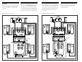
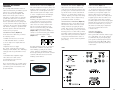
Instruction
Manual
5601 METRO DRIVE,
BALTIMORE, MARYLAND 21215, USA,
410-358-3600, FAX: 410-764-5266
http://www.polkaudio.com
RM7509-1
RM SERIES
RM7500
A WORD FROM MATTHEW POLK
GETTING STARTED
Dear Music Lover,
The complete RM7500 comes in two cartons.
Carton 1 contains the following items:
Thank you for choosing Polk’s RM7500
Home Theater System.
Designing and building speakers is more
than just a business for the people at Polk
Audio—it is our passion.
In addition to these loudspeakers, we make
a complete line of stereo, multimedia and
automotive loudspeakers so you can assemble
the high performance sound system of your
dreams in your home, office and car.
We encourage you to pursue your audio
vision. Find out more about the full line
of Polk Audio products by consulting your
Polk Audio dealer, or by calling our friendly
Customer Service Representatives. In North
America, call 1-800-377-7655, Monday
through Friday, 9:00am through 6:00pm, EST.
• Four (4) magnetically shielded satellite
speakers with integrated brackets
• One (1) magnetically shielded center channel speaker with integrated brackets
Carton 2 contains the following item:
• One (1) PSW650 powered subwoofer
in a special Hi-Gloss finish
Please inspect each loudspeaker carefully.
Be certain that your PSW650 subwoofer
matches the Hi-Gloss finish of your satellites. Notify your Polk Audio dealer if you
notice any difference, damage, or any missing
items. Keep the carton and packing material.
They will do the best job of protecting your
speakers if they need to be transported.
Enjoy your new home theater system!
MARK HERE
CIL
WITH A PEN-
HOLE
FOR SCREW
LOCATIONS
Sincerely,
Matthew S. Polk
Chairman and Co-Founder
A wealth of information can also be
found on our award-winning web site:
www.polkaudio.com
TEAR AT PERFORATION
2
ATTACH YOUR RECEIPT HERE AND
FILE FOR FUTURE REFERENCE.
IT MAY BE REQUIRED FOR WARRANTY SERVICE.
SPEAKER PLACEMENT
(Figure 1)
CENTER CHANNEL SPEAKER
Place the center channel speaker as close
to your TV as possible. The most popular
placement for center channel speaker is
right on top of your TV set. The unique slender design of the RM7500 center channel
speaker makes it easy to mount on the wall
directly above your TV, especially if you
have a slim line or flat screen.
FRONT SATELLITES
The front satellite and center channel speakers of the RM7500 system are specifically
designed to complement flat screen and inset
display televisions by mounting unobtrusively
on the wall flanking the TV. The innovative
design and integrated brackets of the
RM7500 satellites makes them easy to
mount. They also sound great on stands,
bookshelves, or in entertainment centers.
It’s a good idea to place the front satellites
about as far apart as the distance you are
sitting from them. Avoid placing them less
than two feet from the side walls of the
room. When mounting the speakers on
stands or on a shelf, place them at or near
your ear level.
SURROUND SPEAKERS
The best placement for surround channel
speakers is on the side walls, facing each
other, a foot or two behind your listening
position. If this placement is not possible,
the speakers may be placed on a rear wall.
In either case, mount the speakers two to
four feet above your head (when seated).
Note: To avoid marring the finish of your
television, A/V furniture or speakers, use
the “bump-ons” (adhesive rubber feet)
that are packaged with this manual.
FIGURE 1
SUBWOOFER
CENTER CHANNEL
LEFT
CHANNEL
RIGHT
CHANNEL
Y
X
REAR SPEAKERS
X=Y=Z
Z
REAR SPEAKERS
3
POWERED SUBWOOFER
WALL-MOUNTING THE SATELLITES
The RM7500 System uses a specially
finished Polk Audio PSW650 Powered
Subwoofer to round out its surround sound
capabilities. This subwoofer module may be
placed behind furniture or next to a sofa or
chair. It can be placed anywhere in the room,
but you will get the best performance from
it when it is on the same side of the room
as the front satellites. Placing it near a wall
(good) or in a corner (better) enhances its
delivery of lower frequencies. Allow at least
6 inches (15cm) of space between any
subwoofer driver and any wall or obstruction. (Figure 2)
All five satellites of the RM7500 system have
integrated wall-mounting brackets built onto
the rear of each speaker. On-wall installation
of the RM speakers requires basic skills and
basic tools (drill and screwdriver). If you are
in doubt that you possess the necessary
skills or tools, consult your Polk dealer or a
professional installer. Otherwise, follow the
steps below to safely secure the speakers
to the location of your choice.
Set the subwoofer on its feet. (Figure 3)
NEVER LAY THE SUBWOOFER ON THE
AMPLIFIER END–THIS WILL DAMAGE
THE AMPLIFIER.
This subwoofer is not magnetically shielded
and should not be placed close to a television
set. If you see any color distortion on your
TV, move the subwoofer away from the set.
• Make sure the locations you have selected
for wall-mounting do not conceal electrical
wiring or plumbing.
• Hold the speaker in the chosen location to
make certain it clears the ceiling, adjacent
walls, corners, beams, lighting fixtures and
door/window frames.
CONNECTING THE SPEAKERS
TO YOUR SYSTEM
GENERAL
• Use two-conductor 16-gauge (or thicker)
audiophile grade speaker wires.
• Measure enough wire to reach from your
receiver or amplifier to each speaker plus
an additional 12" to allow moving the speakers or receiver without having to disconnect
the wires.
• One of the terminals on the rear of the
speaker is marked red (+) and the other
black (-). Make certain that you connect
the wire from the red (+) terminal of your
receiver or amplifier to the red (+) terminal
on your speaker, and the wire from the black
(-) terminal of your receiver or amplifier to
the black (-) terminal on your speaker. Most
wire has some indication (such as color
code, ribbing, or writing) on one of the two
conductors to help maintain consistency.
• If your speakers sound “thin,” with
little bass and little or no center image,
chances are that one of the speakers
wires is connected backwards. Doublecheck all connections.
To connect wire to the binding post, unscrew
the plastic hex nut on the binding post and
insert the bare wire into the hole near the
base of the binding post. Do not insert the
insulated part of the wire into the hole; this
will not give you a good connection. Twist the
hex nut back down the binding post until it
firmly meets the wire. Do not over-tighten.
(Figure 4)
• If you are certain that there is a stud
behind the wall surface, drive a #10 screw
(not supplied) through the wall and into the
stud leaving the screw head protruding 1/8".
• If there is no stud behind the chosen location, install a #10 wall anchor (not supplied)
into the wall by following the wall anchor
manufacturer’s directions, leaving the screw
head protruding 1/8".
• Line up the speaker so that the screw
head passes through the large center
hole of the bracket’s keyhole slot. Let the
speaker slide straight down, allowing the
screw head to slip behind the smaller end
of the keyhole slot.
FIGURE 4
FIGURE 3
FIGURE 2
OK
Driver Side
≥ 6 inches (15cm)
From wall
4
yyy
;;;
LOOSEN HEX NUT
INSERT SPEAKER WIRE
THROUGH HOLE
TIGHTEN HEX NUT
DO NOT INSERT
INSULATED SECTION
OF SPEAKER WIRE
5
HOOK-UP OPTIONS
The versatile RM7500 loudspeaker system
gives you many hook-up options. Each option
has advantages and potential downsides.
The option that is best for you depends on
your electronics and your personal taste.
The hook-up option you choose may have
a subtle effect on the overall sound of your
system. You may want to experiment with
options to see what works best for you.
Remember, there is no “one best method,”
although we do recommend options 1
(easiest) and 4a or 4b (best sounding).
Option #
Equipment
PSW Input &
PSW Output
Hi-Pass Crossover
Speaker Level
Phase
Setting
Low-Pass
Position
See Page 13
See Page 13
Sat/Sub Setting In
“Speaker Setup” Or
“Bass Management”
Use LFE Output
Or Subwoofer Out?
R E C O M M E N D E D
(Dolby® Digital Only)
1 – Receiver or
Processor with
Subwoofer “Out”
(Figure 5)
Front: “Large”
Sub: “On”
Input: Line Level from
Unfiltered “Sub Out” Or:
“LFE/Subwoofer In” from
Filtered “Sub Out” (see page 8)
Remarks
See Page 12
S E T T I N G S
YES
N/A
Normal
This is the most convenient option.
But be sure to use correct input
(filtered or unfiltered, see page 8)
for your receiver.
NO
Full Range
Normal
Easy to set up. Eliminates
most hum & noise, offering
excellent performance. In most
systems, this is the preferred
hook-up option.
YES
Full Range
Normal
Similar to 2a, may offer
improved bass performance,
satisfies “The LFE Urge.”
NO
N/A
Normal
Clean signal with potentially
lower distortion at high
volume level. But on some
systems, “line level” may
lack adequate gain.
YES
N/A
Normal
Similar to 3a, may offer
improved bass performance,
satisfies “The LFE Urge.”
NO
N/A
Normal
May provide improved
midrange clarity and will
allow the sats to play at
higher volume before
distortion becomes evident
YES
N/A
Normal
Similar to 4a, may offer
improved bass performance,
satisfies “The LFE Urge.”
Output: None
2a – Pro Logic®,
Dolby Digital or
Stereo
(Figure 6)
Front: “Large”
Sub: “Off”
2b – ProLogic,
Dolby Digital or
Stereo
(Figure 6)
Front: “Large”
Sub: “On”
3a – Equipment with
Pre-Amp Out Options
(Figure 7)
Front: “Large”
Sub: “Off”
Input: Speaker Level
Output: Speaker Level to Sats
Input: Speaker Level (L & R)
+ LFE Line Level
Output: Speaker Level to Sats
Input: Line Level
from Pre-Outs
Output: None (Sats Direct
from Receiver or Amp)
3b – Pre-Out Options
For L, R and LFE
(Figure 7)
Front: “Large”
Sub: “On”
Input: Line Level
from Pre-Outs + LFE Line Level
Output: None (Sats Direct
from Receiver or Amp)
6
4a – Equipment with
Pre-Out & Power Amp
“In” Jacks
(Figure 8)
Front: “Large”
Sub: “Off”
4b – Equipment with
Pre-Out & Power Amp
“In” Jacks
(Figure 8)
Front: “Large”
Sub: “On”
Input: Line Level
from Pre-Outs
Output: Line Level
Out to Amp
Input: Line Level
from Pre-Outs + LFE Line Level
Output: Line Level
Out to Amp
7
YOUR SUBWOOFER OUTPUT:
FILTERED OR UNFILTERED?
Use the “speaker set-up” or “bass management” function of your Dolby Digital processor to select subwoofer as “on” or “yes.”
In Dolby® Pro Logic® systems the subwoofer
output jack will always be “ON.” Connect the
subwoofer output jack to the “LFE/Subwoofer”
input of the subwoofer. Disconnect the other
speakers in the system so that all you can
hear is the subwoofer. Play music or a movie
with vocal content. If you can hear and
understand the words, your output jack is
not filtered, in which case you want to use
one of the (line level) “in” jacks on the sub-
woofer itself. If all you can hear is bass,
and the vocals are not at all or barely
audible, then your subwoofer input jack is
filtered and you should use the subwoofer’s
“LFE/Subwoofer In.”
EASIEST HOOK UP OPTION
FIGURE 5
(Refers to Hook Up Option #1 on Chart, Pages 6-7)
FIGURE 6
(Refers to Hook Up Option #2 on Chart, Pages 6-7)
2
Alternate Hook-Up Option*
* To determine proper input jack for your system, see
“Your Subwoofer Output: Filtered Or Unfiltered?” (above).
8
9
AC POWER
The subwoofer has a built-in power amplifier
and must be plugged into a standard household 110-120V AC power source in order
to operate.
FIGURE 7
The power switch has three positions: “On,”
“Off,” and “Auto” (Figure 9, page 13). In
the “Auto” position, the amplifier will automatically turn on, and the green pilot light
on the front of the subwoofer will illuminate
as soon as the speaker senses a signal coming from your electronics. The amplifier and
(Refers to Hook Up Option #3 on Chart, Pages 6-7)
FIGURE 8
3
10
the green pilot light will turn off approximately 15 minutes after input signal ceases.
In the “On” position, the power amplifier will
operate and the green pilot light will illuminate until the switch is set to “Off” position
or the AC cord is disconnected from a
power source.
We recommend using the “Auto” position.
Turn it to “off” if the system will not be
used for extended periods of time, such
as during vacations.
(Refers to Hook Up Option #4 on Chart, Pages 6-7)
4b
11
ADJUSTING THE POWERED
SUBWOOFER
The specially finished PSW650 Powered
Subwoofer included in your RM7500 System
features two 10-inch direct radiating
drivers, 250-watt power amplifier, and
dual Power Port bass ports. It offers a
wide range of setting options. To perfectly
optimize this subwoofer we recommend
the following settings as starting points,
but the option that is best for you depends
on your electronics, main speakers and personal taste. After you have become familiar
with what the settings do, experiment with
alternate options to find the method that
works best for your system.
SUBWOOFER SETTINGS
(Figure 9)
On the back of the subwoofer, you will see
the following controls:
(Figure 9)
This control adjusts the frequency range over
which the subwoofer operates. It only affects
signals that are sent through the line level,
subwoofer and speaker level inputs. It has
no effect on signals fed into the LFE input.
VARIABLE LOW PASS CROSSOVER
RECOMMENDED CROSSOVER SETTINGS —
ON WALL & OFF WALL
Mounting your right and left front satellites
on the wall tends to increase their bass.
Mounting them on stands away from the
sides of the room tends to decrease their
bass. If you mount the satellites on the
wall, we recommend setting your variable
crossover control at a lower setting.
(Figure 10) If you mount the satellites on
stands, we recommend setting your variable
crossover control at a higher setting.
(Figure 11)
FIGURE 10
FIGURE 11
• Variable Low Pass Crossover Control
(Figure 9a)
Subwoofer level is adjusted via the knob
on the front of the subwoofer under the logo
pod. Play a piece of music that has an average amount of bass content. Start with the
knob set to “5” and the Phase switch set to
“normal.” Adjust by ear using a wide variety
of CDs and video sources. Adjust for deep,
powerful bass without “boominess.”
SUBWOOFER LEVEL CONTROL
(Figure 9)
Changing the phase of your subwoofer can
affect its bass “attack.” If the bass sounds
muddy or unclear, try toggling the phase
control. Have someone else switch between
the two settings while you sit in your favorite
listening position. Use music with good bass
(preferably “plucked” string bass) and a deep
male vocal. When you hear the best balance
of deep bass and natural lower octaves of
the male voice, you have achieved optimum
phase tuning.
SWITCHABLE PHASE ALIGNMENT
• +3dB Switchable Bass Boost Switch
(to boost output of low output subwoofer
output jacks)
• High Pass Crossover Toggle
The “80 Hz” setting provides extra bass
filtering for front satellites. The “Full Range”
setting provides best performance in most
cases.
• Switchable Phase Alignment Toggle
• The Subwoofer Volume Control
is found under the logo pod on the
front of the subwoofer.
Generally, turning the knob “up” (clockwise)
will add more “warmth” to the bass and
lower midrange, possibly at the sacrifice
of bass “tightness” and midrange clarity.
Conversely, turning the knob “down” (counter
clockwise) will make the bass and lower
midrange sound “thinner.”
(Figure 9)
In most cases, this switch should be set to
“0.” If you have hooked up your subwoofer
from a subwoofer output or pre-out jacks
and cannot get enough bass output even
with the subwoofer level control turned
all the way up, switch to the +3dB position.
In typical systems where the 3dB boost is
not needed, this switch can be useful for
providing a quick boost for bass-shy program
material. Most people prefer more bass output for movies than music so you can use
this switch as a handy way to adjust bass
levels as you switch between movie
to music sources.
+3dB BASS BOOST
HIGH PASS CROSSOVER—
SPEAKER LEVEL (Figure 9)
Most systems will sound best with the toggle
set to “Full Range.” The “80 Hz” setting is
recommended only if you frequently play
your system at extremely high levels and
prefer hook-up options 2 (a & b). Adjust
variable low pass upward if you make use
of this feature.
FIGURE 9
FIGURE 9a
These controls allow you to optimize performance of the powered subwoofer to match
your audio system, room acoustics, and
program material.
5
12
13
Q. “WHY DOES MY SYSTEM HUM?"
SAFE LIMITS OF OPERATION
A. BECAUSE IT DOESN'T KNOW THE WORDS.
Your Polk Audio loudspeakers are made with
the highest-quality materials, insuring years
of great sounding, trouble-free performance.
However, damage to loudspeakers can occur
when an amplifier, regardless of its wattage,
is made to play at higher listening levels that
its power can clearly produce. (This is usually beyond the “1 to 2 o’clock” position on the
volume control.) This results in very high
levels of audible distortion originating in the
amplifier, which adds a harsh, gritty sound
to the music you're listening to.
This is what passes for humor in the
audio business.
Here’s the real answer:
If you have any electrical (60Hz) hum in your
system, you're going to hear it clearly as
soon as you hook up your subwoofer. Most
hum problems are caused by “ground loops.”
That is, the electrical grounds of the components in your system are not at the same
electrical potential. A very common ground
loop source is cable TV. Disconnect the coaxial cable from your TV and/or VCR. If the hum
goes away, the cable is the ground loop villain. In that case you need a 75 ohm ground
loop isolator. This device is about the size of
a pen and is attached to your coaxial cable
where it plugs into your VCR (or television).
You can obtain this device from some audio
dealers, Radio Shack stores, Zantech (1-800843-5465) or Channel Plus (1-800-999-5225).
Contrary to popular belief, a speaker is more
likely to be damaged by trying to get too
much volume from a low-powered amp or
receiver (than from a high-powered one).
MAINTAINING THE APPEARANCE
OF RM SERIES SPEAKERS
Your new speaker cabinet is made of a
rugged material that can be dusted or
cleaned with a moist cloth. Avoid harsh
detergents and cleaning fluids; they can
permanently damage the finish of your
speakers. Gently vacuum the grilles to
remove dust.
TECHNICAL ASSISTANCE OR SERVICE
If, after following these hook up directions,
you experience difficulty, please doublecheck all wire connections. Should you
isolate the problem to the speaker, contact
the authorized Polk Audio dealer where you
made your purchase, or call Polk Audio’s
friendly Customer Service Department at
1-800-377-7655 (calls from US or CAN only)
from 9am to 6pm Eastern Standard Time,
Monday through Friday. You may also contact
us via email: [email protected].
Ground loops and hum can also be the result
of faulty electrical wiring in your home.
Consult a licensed electrician to evaluate
and, if necessary, repair the AC wiring in
your home. Light dimmers also tend to introduce noise into audio systems. Remove them.
If none of our suggestions work for you, call
our customer service number.
14
15
POLK AUDIO LIMITED WARRANTY
SPECIFICATIONS
RM7500
RM75C
PSW650
System
Overall Frequency Response:
Center Channel
(Magnetically Shielded)
Subwoofer
25Hz - 25kHz
Driver Complement:
Driver Complement:
-3dB Limits:
28Hz - 23kHz
Mid-Bass: 2 - 5 1/4" (13.3cm) Polypropylene
Composite with Rubber Surround,
Tweeter: 1 - 1" (25mm) Dome,
Nominal Impedance:
Compatible with 8 Ohm Outputs
Variable (80-100 Hz Recommended)
57 lbs • 25.9 kgs
250 watts into 4 Ohms
Sensitivity:
91dB SPL @ 1m,
2.83 Vrms Drive Level
Shipping Weight (box 2):
61 lbs • 27.7 kgs
RM75S
Front & Rear Satellites
(Magnetically Shielded)
Driver Complement:
Mid-Bass: 1 - 5 1/4" (13.3cm) Polypropylene
Composite with Rubber Surround,
Tweeter: 1 - 1" (25mm) Dome,
Overall Frequency Response:
60Hz-25kHz
-3dB limits:
90Hz-23kHz
Sensitivity:
89dB SPL @ 1m,
2.83 Vrms Drive Level
Crossover Topology:
Mid-Bass Driver:
1st Order High-Pass @ 80Hz
2nd Order Low-Pass Filters
Tweeter:
2nd Order High-Pass
(Mylar Film Capacitors in Signal Path)
Mid-Bass-to-Tweeter Acoustic Crossover
@ 2.5kHz
Enclosure Type:
Vented, Power Port
Wall Mounting:
Power Port Bracket
on rear of Enclosure
Recommended Amplifier Power:
20-150 Watts/Channel
Dimensions:
11 1/2"H x 9 1/2"W x 5 1/2"D
29.2cmH x 24.1cmW x 14.0cmD
Shipping Weight (pair):
20 lbs • 9.1 kgs
System Acoustic Efficiency
89 dB at 1 meter
Calculated Maximum Output (in-room)
114dB at 1 meter
Crossover Topology:
Mid-Bass Driver:
1st Order High-Pass @ 80Hz
2nd Order Low-Pass filters Cascaded,
-6dB re Midband Level @ 1.8 and 2.8kHz
Tweeter:
2nd Order High-Pass
(Mylar Film Capacitors in Signal Path)
Mid-Bass-to-Tweeter Acoustic Crossover
@ 2.3kHz
Impedance:
Compatible with 8 Ohm Outputs
Enclosure Type:
Vented, Dual Power Port
Wall Mounting:
Power Port Brackets
on rear of Enclosure
Recommended Amplifier Power:
20 - 150 Watts/Channel
Dimensions:
6 1/4"H x 21 1/2"W x 5 1/2"D
15.9cmH x 54.6cmW x 14.0cmD
Shipping Weight (each):
17 lbs • 7.7 kgs
Enclosure Type:
Direct Radiating, Vented
Port Type:
Dual, Power Port, Rear Firing
Overall Frequency Response:
25Hz - 180Hz
-3dB Limits:
28Hz - 125Hz
Variable Low-Pass:
40 - 120Hz, 4th Order
Fixed High-Pass:
Line Level: 80Hz, 2nd Order
Speaker Level: 80Hz, 1st Order
Bass Boost:
0 or +3dB
Phase Control:
Switch Normal and Reverse (0º or 180º)
Inputs:
Speaker and Line Level (Filtered)
LFE Line (Unfiltered)
Outputs:
Impedance:
Compatible with 8 Ohm Outputs
Dynamic Power Rating*
-3dB limits:
90Hz - 23kHz
Shipping Weight (box 1):
165 watts into 4 Ohms @ 1% THD over
power bandwidth of 30 - 120Hz
Overall Frequency Response:
60Hz - 25kHz
Satellite-Center to Sub Crossover:
2 - 10"(25cm) Woofers
Continuous Average Power*
* About Power Ratings
When making comparisons between product
specifications it helps to understand what they
mean, particularly with amplifier power ratings.
The Federal Trade Commission has recently issued
new regulations regarding the power ratings of all
amplifiers including self-powered speakers. Polk
Audio supports this effort to standardize power
testing methods in order to provide consumers with
a “level playing field” basis for comparison. Make
sure the basis for the power rating is clearly stated
before comparing it to another product’s specification.
Speaker Level, Pass-Through or 80Hz HighPass Filtered (Switchable)
Line Level, High-Pass Filtered at 80Hz
Dimensions:
18 3/4"H x 17 1/2"W x 18 3/4"D
47.6cmH x 44.5cmW x 45.7cmD
Shipping Weight (each):
61 lbs • 27.7 kgs
The FTC rating is based on the continuous power output of the amplifier. However, music and movies are not
continuous but are mainly composed of short bursts of sound. For this reason we also supply a “Dynamic Power”
rating which measures the ability of the amplifier to produce power in short bursts similar to those found in music
and movies. In our experience an amplifier with higher Dynamic Power output will play louder under most conditions regardless of the continuous power rating. Dynamic Power is typically greater than continuous average
power although it is not uncommon for two amplifiers with identical FTC “Continuous Average” ratings to have
very different Dynamic Power performance.
However, loudspeaker efficiency is by far the most important factor in determining how loud your system will
play. Loudspeaker efficiency is usually given as the amount of sound produced by 1 watt at a distance of 1 meter.
A medium efficiency loudspeaker rating would be around 87 dB from 1 watt at 1 meter. A highly efficient loudspeaker might be 90 dB. Each 3dB increase in efficiency doubles the sound output for a given power input. So
a 100 watt, 90 dB self-powered speaker and a 200 watt 87 dB unit would produce the same sound output. For
this reason we also specify the loudspeaker efficiency and calculated maximum sound output.
Polk Audio and the Consumer Electronics Manufacturer‘s Association are currently engaged in an effort to set
standards for specifying the actual acoustic output of self-powered speakers. If we are successful, consumers
will be able to use these ratings to make more meaningful product comparisons and better purchasing decisions
in the future.
16
Note: Specifications are subject to change without notice.
Warranty for Satellites and
Center Channel Loudspeakers
Polk Audio, Inc. warrants to the original purchaser only that this Polk Audio Loudspeaker
Product (the “Product”) will be free from defects
in materials and workmanship for a period of
five (5) years from the date of original retail
purchase from a Polk Audio Authorized Dealer.
However, this Warranty will automatically
terminate prior to the expiration of the five (5)
years if the original retail purchaser sells or
otherwise transfers the Product to any other
party. The original retail purchaser shall hereinafter be referred to as “you.”
Warranty for PSW650 Subwoofer
Polk Audio, Inc., warrants to the original purchaser only that the amplifier in this Polk Audio
Loud-speaker Product (the “Product”) will be
free from defects in material and workmanship
for a period of three (3) years from the date
of original retail purchase from a Polk Audio
Authorized Dealer. Polk Audio, Inc., further
warrants to the original purchaser only that
the Loudspeaker(s) in this Polk Audio Product
(the “Product”) will be free from defects in
material and workmanship for a period of five
(5) years from the date of original retail purchase from a Polk Audio Authorized Dealer.
The original retail purchaser shall hereinafter
be referred to as “you.” However, this Warranty
will automatically terminate prior to the expiration if you sell or otherwise transfer the Product
to any other party.
To allow Polk Audio to offer the best possible
warranty service, please fill out the Product
Registration Card(s) and send it to the Factory,
at the address provided on the Product Cards(s)
within ten (10) days of the date of purchase.
Defective Products must be shipped, together
with proof of purchase, prepaid insured to
the Polk Audio Authorized Dealer from whom
you purchased the Product, or to the Factory
at 2550 Britannia Boulevard, Suite D,
San Diego, California 92173. Products must
be shipped in the original shipping container
or its equivalent; in any case the risk of loss
or damage in transit is to be borne by you.
If upon examination at the Factory or Polk
Audio Authorized Dealer it is determined that
the unit was defective in materials or workman
ship at any time during this Warranty period,
Polk Audio or the Polk Audio Authorized Dealer
will, at its option, repair or replace this Product
at no additional charge, except as set forth
below. All replaced parts and Products become
the property of Polk Audio. Products replaced or
repaired under this warranty will be returned to
you, within a reasonable time, freight prepaid.
This warranty does not include service or parts
to repair damage caused by accident, disaster,
misuse, abuse, negligence, inadequate packing
or shipping procedures, commercial use, voltage
inputs in excess of the rated maximum of the
unit, cosmetic appearance of cabinetry not
directly attributable to defect in materials or
workmanship, or service, repair, or modification
of the Product which has not been authorized
or approved by Polk Audio. This warranty shall
terminate if the Serial number on the Product
has been removed, tampered with or defaced.
This warranty is in lieu of all other expressed
Warranties. If this Product is defective in materials or workmanship as warranted above, your
sole remedy shall be repair or replacement as
provided above. In no event will Polk Audio, Inc.
be liable to you for any incidental or consequential damages arising out of the use or inability
to use the Product, even if Polk Audio, Inc. or a
Polk Audio Authorized Dealer has been advised
of the possibility of such damages, or for any
claim by any other party. Some states do not
allow the exclusion or limitation of consequential damages, so the above limitation and exclusion may not apply to you.
All implied warranties on this Product are
limited to the duration of this expressed
Warranty. Some states do not allow limitation
on how long an implied Warranty lasts, so the
above limitations may not apply to you. This
Warranty gives you specific legal rights, and
you also may have other rights which vary
from state to state.
This Warranty applies only to Products purchased in the United States of America, its
possessions, and U.S. and NATO armed forces
exchanges and audio clubs. The Warranty terms
and conditions applicable to Products purchased
in other countries are available from the Polk
Audio Authorized Distributors in such countries.
“Polk Audio” and “The Speaker Specialists are trademarks of Britannia Investment Corporation
used under license by Polk Audio Incorporated.
Dolby, Pro Logic, and AC-3 are registered trademarks of Dolby Laboratories Licensing Corporation.
17