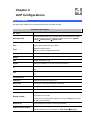
1
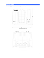
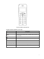
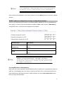
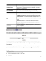
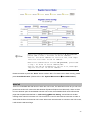
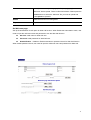
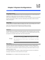
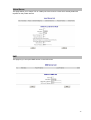
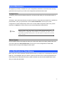
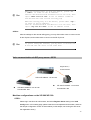
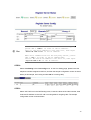
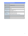
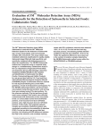
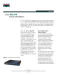
H.323/SIP DECT VoIP router
VIP-320
User’s manual
1
Copyright
Copyright (C) 2005 PLANET Technology Corp. All rights reserved.
The products and programs described in this User’s Manual are licensed products of PLANET Technology, This
User’s Manual contains proprietary information protected by copyright, and this User’s Manual and all
accompanying hardware, software, and documentation are copyrighted.
No part of this User’s Manual may be copied, photocopied, reproduced, translated, or reduced to any electronic
medium or machine-readable form by any means by electronic or mechanical. Including photocopying, recording,
or information storage and retrieval systems, for any purpose other than the purchaser's personal use, and without
the prior express written permission of PLANET Technology.
Disclaimer
PLANET Technology does not warrant that the hardware will work properly in all environments and applications,
and makes no warranty and representation, either implied or expressed, with respect to the quality, performance,
merchantability, or fitness for a particular purpose.
PLANET has made every effort to ensure that this User’s Manual is accurate; PLANET disclaims liability for any
inaccuracies or omissions that may have occurred.
Information in this User’s Manual is subject to change without notice and does not represent a commitment on the
part of PLANET. PLANET assumes no responsibility for any inaccuracies that may be contained in this User’s
Manual. PLANET makes no commitment to update or keep current the information in this User’s Manual, and
reserves the right to make improvements to this User’s Manual and/or to the products described in this User’s
Manual, at any time without notice.
If you find information in this manual that is incorrect, misleading, or incomplete, we would appreciate your
comments and suggestions.
CE mark Warning
The is a class B device, In a domestic environment, this product may cause radio interference, in which case the
user may be required to take adequate measures.
Trademarks
The PLANET logo is a trademark of PLANET Technology. This documentation may refer to numerous hardware
and software products by their trade names. In most, if not all cases, their respective companies claim these
designations as trademarks or registered trademarks.
Revision
User’s Manual for PLANET H.323/SIP VoIP Router:
Model: VIP-320
Rev: 1.0 (June 2005)
Part No. EM-VIP320V1
2
TABLE OF CONTENTS
Chapter 1 Introduction .......................................................................... 5
Overview............................................................................................................................5
Package Content ...............................................................................................................6
Physical Details .................................................................................................................7
LED Display & Button...............................................................................................8
DCT-100 installation ................................................................................................10
Chapter 2 Preparations & Installation .................................................11
Physical Installation Requirement ................................................................................ 11
LAN/WAN Interface quick configurations...............................................................12
LAN IP address configuration via web configuration interface...............................12
WAN IP address configuration via web configuration interface ..............................13
Chapter 3 Network Service Configurations....................................... 15
Configuring and monitoring your VIP-320 from web browser .................................15
Overview on the web interface of VIP-320..............................................................15
Manipulation of VIP-320 via web browser ..............................................................15
Chapter 4 VoIP Configurations ........................................................... 17
VIP-320 Status ................................................................................................................17
Line Setting ..............................................................................................................18
Tone Config ..............................................................................................................19
VoIP Call Out............................................................................................................20
VoIP Call In ..............................................................................................................22
Call Setup .................................................................................................................25
Call Forwarding........................................................................................................26
Register Server................................................................................................................28
WebCall ....................................................................................................................29
WebCall Config ........................................................................................................30
Chapter 5 System Configurations ...................................................... 32
System Config .................................................................................................................32
Bridge Mode Setting.................................................................................................32
Date & Time .............................................................................................................32
Password...................................................................................................................32
Basic Setup ...............................................................................................................32
LAN to WAN Access Rules......................................................................................33
WAN to LAN Access Rules .....................................................................................34
Machine Status................................................................................................................34
Dynamic DNS Setting ..............................................................................................34
DHCP Server Setting................................................................................................35
3
Static Routing ...........................................................................................................35
Virtual Server............................................................................................................36
DMZ .........................................................................................................................36
System Maintenance.......................................................................................................37
Configurations ..........................................................................................................37
Reboot System..........................................................................................................37
Save Modification to Flash Memory.............................................................................37
Appendix A Voice communications...............................................................................38
Peer-to-Peer (P2P) mode ..........................................................................................38
Voice communication via SIP proxy server –SIP50.................................................39
Appendix B VIP-320 Specifications ..............................................................................42
4
Chapter 1 Introduction
1
Overview
With years of Internet telephony and router manufacturing experience, PLANET proudly introduces the
newest member of the PLANET VoIP gateway family: the VIP-320.
As a direct response to feedback from our customers, PLANET's new VoIP gateway, the VIP-320, not
only provides quality voice communications, Internet sharing capabilities with other LAN users, but also
offers DECT interface for daily wireless telephony communications. With advanced DSP processor and
cutting edge VoIP technology, the PLANET VIP-320 is capable of handling both SIP and the H.323
calls. Up to 4 registrations to the SIP proxy or H.323 Gatekeeper, the VIP-320 is able to make calls to
either H.323 or SIP voice communication environment. The VIP-320 is the ideal choice for Voice over
IP communications and providing integrated Internet sharing features, such as Virtual server, SPI
firewall protection, and DMZ support; with these features, users may now enjoy high quality voice calls
and secure Internet access without interfering with routine activities. To bring the users most flexibility,
the add-on RJ-11 interface for PSTN connection, users not only can make the daily PSTN
communication, but also enjoy the convenience brought by VoIP communications.
With built-in DECT & GAP Compatible base, up to 8 DECT handsets can be registered on the VIP-320.
The pan-European users can be benefit from the DECT interface, voice communications can be
established from anywhere in the living space. The PLANET VIP-320 comes with an intuitive,
user-friendly, yet powerful web management interface, no expertise required for the VoIP
communications.
Firewall/Security Feature
•
Built in NAT firewall, DoS (Denial of Service) protection
•
SPI (Stateful Packet Inspection) firewall
•
Policy-based LAN/WAN access control
•
Virtual server, DMZ
•
Remote administrator authentication
•
Enable/disable VPN pass-through
VoIP Functions
•
H.323 / SIP dual mode communication
•
SIP 2.0 (RFC3261), H.323v3 compliant
•
Peer-to-Peer / H.323 GK / SIP proxy calls
•
Voice codec support: G.711, G.723.1A, G.729A
5
•
Voice processing: Voice Active Detection, DTMF detection/ generation, G.168 echo cancellation
(16mSec.), Comfort noise generation, Call progress detection, Gain Control
DECT Features
•
DECT & GAP Compatible
•
Base can register up to 8 Handsets
•
Intercom call during external call, Call transfer between • handsets , three-way telephone meeting
•
CID 50 locations
•
Redial memory: 3 locations, 20 digits
•
Adjustable ringer volume & melody
•
100 hours standby time, 8 hours talk time
•
Hands-Free, Mute function
•
Call duration time meter
•
Transmitted distance: up to 50~200m indoor / up to 300m outdoor
Package Content
The contents of your product should contain the following items:
DECT VoIP router
DECT handset
Power adapter
Quick Installation Guide
User’s Manual CD
RJ-11 cable x 1
6
Physical Details
The following figure illustrates the front/rear panel of VIP-320.
Front Panel of VIP-320
Rear Panel of VIP-320
7
LED Display & Button
Front Panels
Descriptions
Paring LED
When the base connect to the handset
Battery Charge
When charging the handset’s battery
Handset charge Holder Holder the handset
Intercom
When it pairing
LED Indicators
Descriptions
LINE
LINE LED will light when PSTN line is in use
VoIP
VoIP LED will light when talking through VoIP
Status
The Status LED will be flashing when the machine is operational
Ready
Ready LED will be ON when the registration toward the GK/SIP proxy is
successful
Back Panels
Descriptions
DC9V
Power Adapter connecter
LINE
Connect to the RJ-11 phone line
Reset
Reset to the default setting
LAN 1 / LAN 2
10/100Mbps Ethernet port, used to connect PC or NB
WAN
10/100Mbps Ethernet port, used to connect ADSL or cable modem
ÍNote
The Default LAN IP is http://192.168.0.1 from factory.
Press RESET button on rear panel over 20 seconds will reset
the VoIP Router to this default LAN/WAN IP address and
Username/Password function.
8
Overview of DECT handset DCT-100
Keypad and button definition on DCT-100
Descriptions
INT
Intercom conversation mode
Adjust the volume level during the conversation and menu selection on
the LCD display
Last Number Redial
Hang on / up telephone or pressing until to open /close speaker
C
Cancel and Clear
R
Power on / off
Number 0 –9 and #
The function is as the same as the general phone set
*
Press * to switch PSTN
9
DCT-100 installation
The three rechargeable Ni-MH batteries (AAA size) come with your phone. Install the batteries before
using your phone.
1. Slide the battery cover in the direction of the arrow and pull it out.
2. Remove old batteries, if any, and insert new batteries as indicated, matching correct polarity (+, -).
3. Replace the battery cover, slide the cover up until it snaps shut.
ÍNote
This phone won't work by itself. It should be registered
to the main base unit inside the VIP-320.
Before initial using, it should be charged for 24 hours.
Reversing the orientation may damage the handset.
ÍNote
The battery needs to be replaced if it does not recover
its full storage capacity after recharging.
When replacing batteries, always use good quality Ni-MH
re-chargeable AAA size batteries.
Never use other batteries or conventional alkaline
batteries.
10
Chapter 2
Preparations & Installation
2
Physical Installation Requirement
This chapter illustrates basic installation of VIP-320
•
Network cables. Use standard 10/100BaseT network (UTP) cables with RJ45 connectors.
•
TCP/IP protocol must be installed on all PCs.
For Internet Access, an Internet Access account with an ISP, and either of a DSL or Cable modem (for
WAN port usage)
Administration Interface
PLANET VIP-320 provides GUI (Web based, Graphical User Interface) for machine management and
administration.
Web configuration access
To start VIP-320 web configuration, you must have one of these web browsers installed on computer
for management
•
Netscape Communicator 4.03 or higher
•
Microsoft Internet Explorer 4.01 or higher with Java support
Default LAN interface IP address of VIP-320 is 192.168.0.1. You may now open your web browser, and
insert 192.168.0.1 in the address bar of your web browser to logon VIP-320 web configuration page.
VIP-320 will prompt for logon username/password, please enter: admin / 123 to continue machine
administration.
11
ÍNote
Please locate your PC in the same network segment
(192.168.0.x) of VIP-320. If you’re not familiar with
TCP/IP, please refer to related chapter on user’s manual
CD or consult your network administrator for proper network
configurations.
LAN/WAN Interface quick configurations
Nature of PLANET VIP-320 is an IP Sharing (NAT) device, it comes with two default IP addresses, and
default LAN side IP address is “192.168.0.1”, default WAN side IP address is “172.16.0.1”. You may
use any PC to connect to the LAN port of VIP-320 to start machine administration.
L Hint
In
of
IP
to
general cases, the LAN IP address is the default gateway
LAN side workstations for Internet access, and the WAN
of VIP-320 is the IP address for remote calling party
connect with.
LAN IP address configuration via web configuration interface
Execute your web browser, and insert the IP address (default: 192.168.0.1) of VIP in the adddress bar.
After logging on machine with username/password (default: admin / 123), browse to “Administrator”
--> “LAN setting” configuration menu:
Parameter Description
IP address
LAN IP address of VIP-320
Default: 192.168.0.1
Subnet Mask
LAN mask of VIP-320
Default: 255.255.255.0
Default Gateway
Gateway of VIP-320
Default: 192.168.0.254
12
L Hint
It is suggested to keep the DHCP server related parameters
in default state to keep machine in best performance.
After confirming the modification you’ve done, Please click on the Modify button to macke the changes
effective.
WAN IP address configuration via web configuration interface
Execute your web browser, and insert the IP address (default: 172.16.0.1) of VIP in the adddress bar.
After logging on machine with username/password (default: admin / 123), browse to “WAN Setting”
configuration menu, you will see the configuration screen below:
Connection Type
Data required.
Obtain IP Address
In most circumstances, it is no need to configure the DHCP
Automatically
settings.
Specify an IP Address
The ISP will assign IP Address, and related information.
The ISP will assign PPPoE username / password for Internet
PPPoE
L Hint
access,
Please consult your ISP personnel to obtain proper PPPoE/IP
address related information, and input carefully.
If Internet connection cannot be established, please check
the physical connection or contact the ISP service staff
for support information.
Save Modification to Flash Memory
Most of the VoIP router parameters will take effective after you modify, but it is just temporary stored on
RAM only, it will disappear after your reboot or power off the VoIP router, to save the parameters into
Flash ROM and let it take effective forever, please remember to press the Save Modification button
after you modify the parameters.
13
14
Chapter 3
Network Service Configurations
3
Configuring and monitoring your VIP-320 from web browser
The VIP-320 integrates a web-based graphical user interface that can cover most configurations and
machine status monitoring. Via standard, web browser, you can configure and check machine status
from anywhere around the world.
Overview on the web interface of VIP-320
With web graphical user interface, you may have:
More comprehensive setting feels than traditional command line interface.
Provides user input data fields, check boxes, and for changing machine configuration settings
Displays machine running configuration
To start VIP-320 web configuration, you must have one of these web browsers installed on computer for
management
Netscape Communicator 4.03 or higher
Microsoft Internet Explorer 4.01 or higher with Java support
Manipulation of VIP-320 via web browser
Log on VIP-320 via web browser
After TCP/IP configurations on your PC, you may now open your web browser, and input
http://192.168.0.1 to logon VIP-320 web configuration page.
VIP-320 will prompt for logon username/password: admin / 123
VIP-320 log in page
15
VIP-320 main page
16
Chapter 4
VoIP Configurations
4
VIP-320 Status
This page main display the current and last time VoIP call status & result.
Parameter Description
PC Time
will show the date & time that your connected PC now.
Gateway Time
will show the date & time of this VoIP router, the date amd time is get
from SNTP server. You may setting the SNTP server from “System
Config Administrator
Date & Time”
Ports Message
Port
Type
display FXS interfase the port number.
Telephone interface type:
FXS: for connect to regulate phone set.
Display Name
display the remote party name of this VoIP call.
Status
Current status of this port.
Idle
Standby make phone call.
Signal
Waiting for DTMF key in or VoIP protocol connecting.
In
Out
There is a phone call made from phone port and call out to Network by
VoIP.
There is a phone call made from network VoIP and pick up by phone
set.
Connected IP
The other party IP of this VoIP call.
Caller ID
Caller ID received from phone port.
Start Time
Date & time of this VoIP call begin on this port.
End Time
Date & Time of last VoIP call End on this port.
Talking Sec
Total talked seconds of last VoIP call on this port.
On the VoIP call out (line status display In), This will display the real dial
Dialed number
out number for VoIP call.
On the VoIp call in (line status display out). This will display the number
will dial out to phone line.
Release by
Register Sever Status
This will display the reason of this call termination.
This VoIP router can register to 4 GK/SIP proxy simultaneously. You can
setup the GK/SIP proxy information on “VoIP Config
Register
17
Server”
Error Message
For some reason (ex. All lines of this VoIP router are busy), here will
display the failure information of last time VoIP Call in.
Line Setting
This page will setup the phone line information each port.
Parameter Description
Port
display FXS interfase the port number.
Telephone interface type:
Interface
FXO: for connect to telephone line or PBX extension line.
FXS: for connect to regulate phone set.
Name
Line Number
Line name for this port. This will send and display on the remote side
due VoIP call
Telephone number assigned to this line.
Transmitter Gain. This will adjust the speaker volume of local phone set.
TxGain
The adjust range is from +3 to -13dB. Higher value will cause louder
sound come from local phone set.
Receiver Gain. This will adjust the microphone volume of local phone
RxGain
set. The adjust range is from -3 to +13dB. Higher value will cause
amplifier the sound get from local phone set.
Inbound
Outbound
Hotline
Enable or disable the VoIP call to Internet. Disable the inbound will not
allow any call made call to Internet from phone set.
Enable or disable the VoIP call from Internet. Disable the Outbound will
not allow any call made call from Internet to phone set.
When Enable, it will allow you to make a VoIP call without Key in any
18
number. That mean it will direct call out by VoIP when you off hook the
phone of this line.
Tone Config
This page defines the tones generated to the phone connected to the phone port. All lines use same
tone parameters. After modify the tone parameters, you must save modify then Reboot to let the
modified parameters work.
Parameter Description
Use the parameters to automatic detect cadence busy tone. When
detected a voice cadence repeat over this parameters setting in
Detect Voice Busy Cycle sequence, the VoIP router will treat it like busy tone and disconnect
automatically. Please do not set this parameter less than 5 to avoid
unexpected erroneous disconnect.
You can set up to 15 tones set for detection and generation. For the
Tone define Table
generation, the first entry will be used. The call progress tones, ranging
from 300 Hz to 2000 Hz, are defined for both generation and detection.
Generation, however, can be defined from 1 Hz to 3980 Hz.
Tone
Maximum 15 tones can be defined.
Dial: Define the generated dial tone for phone set
Type
Busy: Define the busy tone for generate & detect
Ring: Define the ring back tone for generate
Low freq
Lower frequency for defined tone
Higher frequency for defined tone. Each tone can define two
High freq
frequencies, if only one frequency needed, please leave High
Frequency to 0.
T_ON_1,T_OFF_1, T_ON_2, The cadence pattern of up to four intervals for each dual-frequency.
T_OFF_2
Minimum Cadence value is 30msec.
19
VoIP Call Out
This page defines the routing rule for Call out to VoIP. (User key in the phone number through phone
set dial pad, then VoIP router translate the phone number by the routing table setting here to
destination IP, and dial out number then call out via network protocol).
Each time when you off hook the phone connected to this VoIP router, you will hear a dial tone to
remind you to key in the phone number, after you input the number you called, if digits of the number of
you called is not exceed the Max Digits, please remember to press the # key for ending the input.
Parameter Description
Define the maximum digits wait for user key in for all VoIP Call Out, if
MaxDigits
user key in digits match the number defined here. It will go to translate
for call out rule without needed to press # key.
Define the waiting seconds for user key in phone number first digit. User
FirstDigitTime
need to key in first digits before the seconds defined here, if VoIP router
wait over the defined seconds and there is no any digits key in, the VoIP
router will feedback the user busy tone.
Define the waiting seconds for user key in phone number secondary &
OtherDigitTime
the rest digits. User need to key in the rest digits before the seconds
defined here, if VoIP router wait over the defined seconds and there is
no any digits key in, the VoIP router will feedback the user busy tone.
Remark
Area Code
Remark for this routing rule. Please use UNDERLINE to replace the
SPACE due to HTTP protocol limitation.
Define the Prefix number fit this rule, any phone number prefix digits
matched with the rule will call out by this rule define. Please Notify there
20
is a compare order rule on this routing table. That mean the VoIP router
will check the rule list from top to bottom one by one, any rule item
matched with the prefix digits that user key in will go to call out directly
no regard to the rest rules below. For Example, if a rule item for area
code 8862 is on Index 5, another rule item for area code 886 on Index 6
below that will be ignored.
By setting the hln (hl1 for hot line one, hl2 for hot line two) on the area
code field, and enable hot line function (Please refer to the “VoIP Config
Line Configure
Line Setting”), the VoIP router can service the
hot line direct call.
Define the minimum digits wait for user key in for number fit this rule, if
user key in digits less the number defined here. It will keep waiting for
Min Digits
input until exceed the “FirstDigitTime” defined time. If user key in digits
more then “Min Digits” here, the VoIP router will wait time defined on
“OtherDigitTime” then go to translate for call out rule without needed to
press “#” key.
Define the maximum digits wait for user key in for number fit this rule, if
Max Digits
user key in digits match the number defined here. It will go to translate
for call out rule without needed to press “#” key.
Define the destination IP for call out number fit this rule, user can input
below format:
IP address, such as: 210.66.155.93
URL, such as: vip.planet.com.tw
Note: This H.323/SIP DECT VoIP router can setup to Uregister to
IP Address
DDNS service. (Please refer to the “System Config
Advanced
Dynamic DNS”) to let user call out to another VoIP router with dynamic
IP by URL.
GK/SIP proxy, such as: it will get the destination IP by register server
setting (Please refer to the “VoIP Config
Register Server”) in
advance.
The number of digits will be ignored by user input.
Strip
For example, if user key in the number is 886222199518 and the
STRIPE field is setting to 4, the first 4 digits 8862 will be truncated and
actually call out number will be 22199518.
The numbers will be added on the prefix of user key in number.
For examples, if user key in the number is 22199518 and the PREFIX
Prefix
field is setting to 0028862, the actually call out number will be
002886222199518.
Another example, if user key in the number is 90, STRIP field is setting
to 2, and the PREFIX field is setting to 0,22199518, the actually call out
21
number will be 0,22199518 ( “, “ mean wait 1 second).
This example is especially for speed dial function.
Define the optional special call out parameters on this destination.
Profile
Please input the name you Udefined on the profile (Please refer to the
“VoIP Config
Routing Setup
Routing Profile”) list.
Delete this rule item on routing table.
Delete
To add new rule item on routing table, please assign the item number you want to insert before, input
AREA CODE and IP address then press ADD button to add it on the list. Then modify the necessary
information on the routing table list.
Please remember to press the modify button to take it effect. For store back to flash memory, please
press ”Syetem Maintenance
L Hint
Save Modification” .
When user enable the hot line function on “VoIP Config
Line Configure
Line Setting” menu, it will over ride the
above parameters and direct call out by hot line call out
rule.
VoIP Call In
This page let you define the routing rule for Call in from VoIP. (VoIP router got a VoIP call required form
network, and then translates the phone number passed from remote side VoIP router to the real dial out
number, and line base on this VoIP call in routing table). Each time when the VoIP router received a
VoIP call from network, it will check with “Area Code” to see which rule matched to service, if no rule
matched, it will refuse to call out and will bound back the call.
When the VoIP router received a VoIP called from network, it will check below rules fields then decide
line and number to dial out.
22
Parameter Description
Define the Prefix number this rule service, any VoIP called from network
dialed number prefix digits matched with the rule will call out to phone by
this rule define. Please Notify there is a compare order rule on this
Area Code
routing table. That mean the VoIP router will check the rule list from top
to bottom one by one, any rule item matched with the prefix digits that
user key in will go to call out directly no regard to the rest rules below.
For Example, if a rule item for area code 8862 is on Index 1, another rule
below that like index 2 for area code 886 will be ignored.
Number of digits will be ignored by user input.
Strip
For example, if received VoIP call number is 886222199518 and the
“STRIPE” field is setting to 4, the first 4 digits 8862 will be truncated and
actually call out number will be 22199518.
The numbers will be added on the prefix of received VoIP call number.
Prefix
For examples, if received VoIP call number is 22199518 and the
“PREFIX” field is setting to 0028862, the actually call out number will be
002886222199518.
Define the maximum digits of call number allow to dial. If the length of
dial number after pervious “STRIP” and “PREFIX” process is more than
Maximum
the setting, it will deny dialing out.
For example, you can set the “Maximum” dial out digits is 8, for call to
local area phone only, any VoIP call in attempt to dial 0222199518 out of
8 digits for call out long distance will been deny to call out.
Define the minimum digits of call number allow to dial. If the length of
dial number after pervious “STRIP” and “PREFIX” process is less than
Minimum
the setting, it will deny dialing out.
For example, if set “Minimum” to 4, any VoIP call in attempt to dial
number less than 4 digits like 110, 911 will been deny to call out.
Define the beginning line number for service this area code VoIP call.
From
For example, if user assigned FROM 1 TO 1 for AREA CODE 601 in this
routing table, then any VoIP call for call in number 601 will ring the line 1
only.
To
Define the ending line number for service this area code VoIP call.
Click to enable if you want to force compare with the line number setting
on ULINE CONFIGUREU menu (Please refer to the “VoIP Config
Line No
Line Config
Line Setting”). If the dial number after pervious STRIP
and PREFIX process is matched with the line number setting, the VoIP
call will ring the dedicate phone line that assigned with matched number.
23
Assign which gatekeeper to authorize this incoming VoIP call before call
out.
Server
For example, if the dial number should be checked by server 1 setting
on the “Regster Server” menu (Please refer to the “VoIP Config
Register Sever”).
When the call is coming , Before or After to pick up the phone , the
Server should check that has the speaker got authorization from
Register Server ?
After:setting on After function , when the call is coming, Server will ring
at first, when user pick up the phone, then Server will go to Register
ANS
Server for checking caller-authorization, if the authorization has
confirmed, then the connection will start to success, otherwise it will sent
busy tone.
Before:setting on Before function , when the call is coming, at fist
Server will go to Register Server to check that has the speaker got
authorization? If the authorization has confirmed, then Server start to
ring, otherwise it will send busy tine.
Control the Ring Back tone generate timing:
Mode 0: When this VoIP ruter get ring back tone from phone line, it will
send the ring Alert signal to remote VoIP router for generate ring back
tone.
Mode 1: Before this VoIP router dial to phone line, it will send the ring
Alert
Alert signal to remote VoIP router for generate ring back tone.
Mode 2: After this VoIP router finish dial out number to phone line, it will
send Connect OK signal to remote VoIP router.
Mode 3: Before this VoIP router dial to phone line, it will send the ring
Alert signal to remote VoIP router for generate ring back tone, after this
VoIP router finish dial out number to phone line, it will send Connect OK
signal to remote VoIP router.
Define the optional special VoIP parameters when received on this
Profile
destination. Please input the name you defined on the profile list (Please
refer to the “VoIP Config
Call Routoing
Call Setup”).
Define the profile name for forward the unanswerable VoIP call on this
Forward
call in rule. Please input the name you defined on the “Forward” profile
list.
Delete this rule item on routing table.
To add new rule item on routing table, please assign the item number
Delete
you want to insert before, input AREA CODE then press ADD button to
add it on the list. Then modify the necessary information on the routing
table list.
24
Please remember to press the modify button to take it effect. For store back to flash memory, please
press “Save Modification” (Plaase refer to the “Syetem Maintenance
Save Modification”).
Call Setup
This page defines the optional special VoIP parameters when making/received a VoIP call. For define
some special parameters for different VoIP equipment or authorize purpose, please add a profile at
“VoIP Config
Call Routing
Call Setup”, and use the same name as the profile on the “Call in
Routing Table” (Please refer to the “VoIP Config
Call Routing
VoIP Call In”) or “Call out
Routing table” (Please refer to the “VoIP Config
Call Routing
VoIP Call Out”).
Parameter Description
Name
Specify a profile name. Please use UNDERLINE to replace the SPACE
due to HTTP protocol limitation.
ON: turn on the VAD (Voice Activity Detection) function.
VAD
OFF: turn off the VAD function, please select ON for save the
bandwidth.
Select different voice CODEC for VoIP communication. The bit rate of
CODEC
G.723.1 is 5.3k/6.3k, G.729 is 8k, uLaw and aLaw is 64k per second.
The G.723.1 is default CODEC.
H.245 tunneling
ON: to enable H.245 tunneling.
OFF: to disable H.245 tunneling.
When select UIn bandU to transfer the DTMF during VoIP, the user
pressed DTMF tone will be treat as general voice and been compressed
then transmit to remote side to decompress play back, it maybe cause
DTMF Relay
some problem on duplicate or missing DTMF receive.
When select “Out band” to transfer the DTMF during VoIP, the user
pressed DTMF tone will be decode by local VoIP router then transmit as
signal, after received on received remote VoIP router, it will be
regenerate by remote VoIP router. The default value is Out band.
T.38 FAX Relay
ON: FAX will be transmitted by using T.38 FAX over IP protocol.
25
OFF: FAX over IP is disable.
Select the voice payload frame on each UDP package VoIP transmit.
Package Frame
More frames into one package is save more bandwidth. The default
frames on each package is 3.
Q.931 Fast Start
ON: Enable Fast Start capability during Q.931 handshaking.
OFF: Disable Fast Start capability during Q.931 handshaking.
User defines ID #1 during this VoIP call.
ID1
E.164: Parameter on ID1 field is the E.164 during this VoIP call.
H.323 ID: Parameter on ID1 field is the H.323 ID during this VoIP call.
Calling: Parameter on ID1 field is DID number during this VoIP call. If
this optional is setting, it will override the LINE NUMBER on line Setting
As
menu.
Password: Parameter on ID1 field is the password for VoIP call.
Parameter defined here will used as MD5 during H.235 and will not
display on the Web UI
ID2,ID3,ID4
Delete
There are 4 fields for user define the ID parameters, please reference
the ID1 setting above.
Delete this rule item on routing table.
To add new profile item on routing table, please assign the number you want to insert before, input
profile NAME then press ADD button to add it on the list. Then modify the necessary information on the
routing table list.
Please remember to press the modify button to take it effect. For store back to flash memory, please
press “Save Modification” (Plaase refer to the “Syetem Maintenance
Save Modification”).
Call Forwarding
This page defines the scenario of call forwarding:
Get an unmatched prefix number for VoIP call in
Line busy
26
No answer
Please add a profile at “VoIP Config
Call Routing
Call out Routing table (Please refer to the “VoIP Config
Call Setup” and put the name of profile on the
Call Routing
/VoIP Call Out”).
Parameter Description
Define the forward IP and forward phone number when there is no
match rule setting on “VoIP Call Out Routing” table. The format is
Other
IP/phone number or URL/phone number. I.e. all the phone number can
find a matched prefix rule will be forward to the IP, and phone number
define on here.
Name
Always
Specify a profile name. Please use UNDERLINE to replace the SPACE
due to HTTP protocol limitation.
Always redirect forward to this IP (or URL)/phone number, original line
will never ring and all incoming call will be forward to IP assigned here.
Redirect forward to this IP (or URL)/phone number when busy, an
On Busy
incoming VoIP call will forward to IP assigned here when this line is
busy.
Redirect forward to this IP (or URL)/phone number when no answer
No Answer
over the time “No Answer Sec” , an incoming VoIP call will forward to IP
assigned here when ring time over the defined on “No Answer Sec”.
No Answer Sec.
Delete
Defined the maximum wait seconds for redirect forward to another IP (or
URL).
Delete this rule item on routing table.
To add new rule item on routing table, please assign the item number you want to insert before, input
AREA CODE then press ADD button to add it on the list. Then modify the necessary information on the
routing table list.
Please remember to press the modify button to take it effect. For store back to flash memory, please
press “Save Modification” (Plaase refer to the “Syetem Maintenance
Save Modification”).
27
Register Server
If this VoIP router want to use GK/SIP proxy service to transfer the VoIP call, you can input the GK /SIP
information here. The VoIP router can register to up to four GK/SIP proxy simultaneously.
Parameter Description
Success: Register successful.
Register Server Status
Failure: Register failure.
Disable: disable register this gatekeeper
MAC
Server1
Remark
Display the MAC address of WAN on this VoIP router
Enable: Enable the VoIP router to register Server #1.
Disable: Disable the VoIP router to register Server #1.
For Notify remark for this Gatekeeper. Please use UNDERLINE to
replace the SPACE due to HTTP protocol limitation.
Click to enable using GK/SIP proxy function. When enable, VoIP call will
go through the GK/SIP proxy service. Please click here if your VoIP
Proxy
router is installed behind NAT or firewall without real IP. If you want use
this function, please make sure your GK/SIP proxy has support the
proxy function.
Define the GK/SIP proxy server IP, user can input below format
IP address:
IP address, such as: 192.198.0.1
URL, such as: vip.planet.com.tw
Prefix
Specific the prefix number of this VoIP router service for register to
gatekeeper.
Specific the ID of this VoIP router for register to gatekeeper
H.323: register above ID as H.323 ID.
E.164: register above ID as E.164 ID.
ID1
User Name: register above ID as user name for H.235 on Gatekeeper.
Password: register above ID as password for H.235 on Gatekeeper.
There are four fields for user define the ID parameters, please reference
the ID1 setting above.
*1:SIP OutboundProxy
To make a call using SIP protocol with proxy server, input the server IP
or domain name in the *1:SIP OutboundProxy field.
28
L Hint
When voice communication is established via H.323 protocol,
please add a ”h323:” in front of the IP address.
Such as: the GK IP address is 192.168.0.100, then input
“h323:192.168.0.100” in the IP address.
When voice communication via the SIP protocol, please add
a “sip:” in front of the IP address/URL.
Such as: the SIP-50 IP address is 192.168.0.50, then input
“sip:192.168.0.50” in the IP address.
Please remember to press the “Done” button to take it effect. For store back to flash memory, please
press “Save Modification” (Plaase refer to the “Syetem Maintenance
Save Modification”).
WebCall
There is a embedded Web Call function within the VoIP router, The Web Call function let you call to the
phone lines of this VoIP router with Web browser IE(Internet Explorer from Microsoft) . When a client
PC uses browser open the embedded web this VoIP router, the embedded VoIP router will send the
page with the parameters defined on “VoIP Config
Web Call Setting”, and will launch the Net
meeting within client PC windows OS. This function let a user PC with Internet connection to make a
VoIP call to the lines connected to VoIP router. When user uses a browser to connect to the VoIP router,
it will show the welcome Page:
29
Parameter Description
Show the IP of this VoIP router
Gateway IP
Select the name you want to make connect, this is defined on Web Call
Name
page. (Please refer to the “VoIP Config
Web Call Setting
Web
call).
Call
Press to make a call.
Stop
Stop the call.
WebCall Config
This page let you define the welcome message, LOGO, call number when using Web Call function.
Web Call accept List:
Define the display name on select option during Web call.
Parameter Description
Name of selectable item during web call.
Name
Number of this selected item call out, when user select the name of this
item rule, the number here will be used as the number for VoIP call In,
Number
and will check with the area code define on “VoIP Config
Routing
Call
VoIP Call In”, that mean you should have a matched item
defined on “VoIP Config
Call Routing
Delete
Delete this rule item on routing table.
Stop
Stop the call.
VoIP Call Out”.
To add new name item on Web Call accept List, please assign the number you want to insert before,
input list item NAME then press ADD button to add it on the list. Then modify the necessary information
on the r Web Call accept List.
Please remember to press the “Modify” button to take it effect. For store back to flash memory, please
press “Save Modification” (Plaase refer to the “Syetem Maintenance
Save Modification”).
BWelcome page and banner Upload:
Define the welcome message and Logo for Web Call function:
Parameter Description
To upload a welcome message HTML file for display on Web Call
User HTML Welcome
Page
function page, this page should be HTML file and there is a file size
limitation, please press the “Browse” button to select the HTML file you
want to upload and press “Upload” to Upload it.
User Welcome page
banner
To upload a logo graphic file for display on Web Call function page, this
graphic file should be name as “Welcome” only and there is no ext file
30
name, please rename your logo graphic file(.bmp, .jpg, .gif) to
“Welcome” before upload. There is a file size limitation. Please press the
Browse button to select the “Welcome” file you want to upload and
press Upload to Upload it.
Delete
Delete this rule item on routing table.
Stop
Stop the call.
Set Welcome page:
Set up the authorization check option for Web Call function. When Enable the authorization check, user
need to input the valid user name and password to use the Web Call function.
Set User: valid name for Web Call user
Password: valid password for Web Call user.
Disable/Enable: Disable or Enable username or password check for Web Call function.
When enable password check, user need to input the valid user name and password for Web Call.
31
Chapter 5 System Configurations
5
System Config
Bridge Mode Setting
This page allows you to disable/enable this device become bridge device or not. When it becomes a
bridge device, bridge interface use LAN's IP address, LAN's subnet mask.
When working on Bridge Mode, the VoIP router will use only the LAN setting IP, The VoIP router will use
the same LAN IP setting as WAN IP. That mean, When Bridge mode enable, the WAN connection
setting will be ignored.
Date & Time
This page allows you to adjust the date & time settings in this router. The time settings are in 24-hour
format. The router also uses the date and time to time stamp to log events.
Note: When you reset the router, you MUST adjust the date and time again.
Password
This page allows you to change the administration password used to manage this router for security
reasons. o set this password, enter your current password in the Old Password field and then enter a
New password in the New Password and Confirm New Password fields.
The Default User name is “admin” and the password is “123”
ÍNote
from factory. Press RESET button on rear panel over 5 seconds
will cause the VoIP router reset to this default user name
and password.
Basic Setup
This router comes with the built-in firewall based on the advanced technology of Stateful Packet
Inspection to protect your network from being attacked by hackers. You can set up network access
rules to decide if the network traffic is allowed to pass through (LAN-to-WAN and WAN-to-LAN) the
firewall built inside the router.
In the following sections, you are able to configure firewall settings in this router. Some advanced
knowledge or experiences in TCP/IP internet work are required.
Basic Settings: You can configure basic firewall settings in this router.
32
LAN-to-WAN Access Rules: You can define LAN-to-WAN network access rules which evaluate the
network traffic's source IP address, destination IP address, and communication port to decide if it's
allowed to pass through the firewall.
WAN-to-LAN Access Rules: You can define WAN-to-LAN network access rules which evaluate the
network traffic's source IP address, destination IP address, and communication port to decide if it's
allowed to pass through the firewall.
LAN to WAN Access Rules
This pages allows you to define LAN-to-WAN network access rules which evaluate the network traffic's
source IP address, destination IP address, and communication port to decide if it's allowed to pass
through the firewall.
By default, the stateful packet inspection module of this router allows all communications to the Internet
that originates from the LAN. The behavior is defined by the default stateful packet inspection enabled
in the router:
Forward all sessions originating from the LAN to the Internet.
Discard all sessions originating from the Internet to the LAN (Pleaes refer to the “WAN-to-LAN
Access Rules” at System Setup
Firewall
WAN-to-LAN Access Rules).
Additional access rules may be defined to extend or overwrite the default rules.
The ability to define network access rules is a very
powerful management tool. Using a custom rule, it's
possible to disable all firewall protection, creating
holes in the firewall, or block all access to the
ÍNote
Internet. Use with extreme caution when creating or
deleting network access rules.
Network access rules will not disable protection from
Denial of Service (DoS) attacks, such as SYN Flood, Ping
of Death, Port Scan, etc. However, it's possible to
create vulnerabilities to attacks that exploit
vulnerabilities in applications.
33
WAN to LAN Access Rules
This pages allows you to define WAN-to-LAN network access rules which evaluate the network traffic's
source IP address, destination IP address, and communication port to decide if it's allowed to pass
through the firewall.
By default, the stateful packet inspection module of this router blocks all traffic to the LAN that
originates from the Internet. The behavior is defined by the default stateful packet inspection enabled in
the router:
Forward all sessions originating from the LAN to the Internet (Pleaes refer to the “LAN-to-WAN
Access Rules” at System Setup
Firewall
LAN-to-WAN Access Rules).
Discard all sessions originating from the Internet to the LAN.
Additional access rules may be defined to extend or overwrite the default rules.
The ability to define network access rules is a very
powerful management tool. Using a custom rule, it's
possible to disable all firewall protection, creating
holes in the firewall, or block all access to the
ÍNote
Internet. Use with extreme caution when creating or
deleting network access rules.
Network access rules will not disable protection from
Denial of Service (DoS) attacks, such as SYN Flood, Ping
of Death, Port Scan, etc. However, it's possible to
create vulnerabilities to attacks that exploit
vulnerabilities in applications.
Machine Status
This page display the Current Status of the VoIP router.
Dynamic DNS Setting
This section allows you to set up advanced features in this router. During the design stage, we have
given much thought to making this router as convenient and easy to use as possible. However, some
more advanced knowledge about TCP/IP might still be required.
Dynamic DNS: Each time the WAN address is changed, DDNS service will automatically update it to
dyndns.org. You can register your account at :http://www.dyndns.org
34
DHCP Server Setting
This page allows you to set up configurations of DHCP server built in the router. The DHCP server of
this router provides IP addresses, the subnet mask, the gateway address, and DNS server addresses
to the LAN computers and devices dynamically. The default IP address space of this DHCP server is
192.168.0.x, with subnet mask 255.255.255.0, and the default gateway of this network is the IP
address of this router (192.168.0.1).
It's highly recommended you use this router as the DHCP server; unless you already have a DHCP
server on the network.
The DHCP server comes with two default IP lease ranges. To add a new dynamic IP range for lease,
click the “Show Current IP Ranges” section.
To view the current dynamic IP assignments from the DHCP server, click “Show IP Lease Table (Show
DHCP leases”.
To assign a fixed-IP for a certain host on private network, click “Show Fixed-IP Table”.
When any change is made on this page, you MUST restart all
ÍNote
PCs to update their TCP/IP settings from this DHCP server.
Static Routing
This page mainly allows you to define a static routing entry in the internal routing table of the router. If
the private LAN has internal routers, their addresses and network information will need to be entered
into this router to find the correct data path when it routes network packets. Static routes are generally
used if the LAN are segmented into subnets, either for size or practical considerations.
Most of users who are using the whole IP address space without sub networks don't have to enter any
entry in this table. The router automatically updates its internal routing table and dynamically notifies
other routers on the network by sending out RIP (Routing Information Protocol) information. This router
supports RIP I and RIP II standards.
To add a new static routing path, click “View or Add Static Routing Table” link.
Adding incorrect routing information can affect the
ÍNote
connection, a local host, or the whole private network. You
must have experience working with routing tables before
using this option.
35
Virtual Server
This page allows you to map a TCP or a UDP port of the router to a host which actually deals with
requests on the private network.
DMZ
This page let you set up the DMZ service on the VoIP router.
36
System Maintenance
This page let you backup / Restore all of your configuration parameters on the VoIP router. It is very
good idea to back up all of your VoIP router configuration parameters after install.
Configurations
To Backup, press Download setting backup file, and input the file name you want and file location to
save.
To Restore, press the Browse button the select the backup configuration parameters file to upload then
press Restore . After you upload the file, Press “Saved modification” to save your current
configuration to Flash ROM (Usually used to save currently WAN configuration).After save, please
remember to “Reboot” the VoIP router to let the restored parameters take effective.
L Hint
Never power off the VoIP router when during Restore
configure or upgrade VoIP module or System, it will cause
permanent damage when power off during writing Flash inside
VoIP router.
Reboot System
Use the Reboot button on this page to reboot your VoIP router, before you reboot, please make sure
you have to press the “Saved modification” to save your current configuration to Flash ROM,
otherwise all the change will be disappear after reboot.
Save Modification to Flash Memory
Most of the VoIP router parameters will take effective after you modify, but it is just temporary stored on
RAM only, it will disappear after your reboot or power off the VoIP router, to save the parameters into
Flash ROM and let it take effective forever, please remember to press the Save Modification button
after you modify the parameters.
37
Appendix A Voice communications
There are several ways to make calls to desired destination in VIP-320. In this chapter, we’ll lead you
step by step to establish your first voice communication via web browsers operations.
Peer-to-Peer (P2P) mode
H.323 IP Phone
IP Address: 172.16.0.100
Number: 1001
VIP-280/320
SIP IP Phone
WAN IP Address: 172.16.0.1
IP Address: 172.16.0.200
Number: 7001
Number: 2001
VIP-280 / VIP-320 configurations:
STEP 1:
Please log in machine via web browser, and select Line Setting in the Line config menu. In
this Line Setting page, please insert the telephone number assigned to this line, and then
the sample configuration screen is shown below (in this sample, we’re using number 7001
for incoming calls).
STEP 2:
Select VoIP Call Out in the Call Routing menu; insert the values of the index number, Area
Code and IP Address on the VoIP call out routing table for outgoing calls. The sample
configuration screen is shown below.
38
When the calling party is an
a ”h323:” in front of the IP
Such as: the destination H.323
input “h323:172.16.0.100” in
VIP-320/VIP-280 VoIP Callout
L Hint
H.323 device, please add
address.
device is 172.16.0.100, then
the IP address column of
setting page
When the calling party is a SIP device, please add a “sip:”
in front of the IP address.
Such as: the destination SIP device is 172.16.0.200, then
input “sip:172.16.0.200” in the IP address field.
STEP 3:
After the settings for the remote calling party, you may dial number 1001 to connect to the
H.323 IP phone, and number 2001 to connect to the SIP IP phone.
If you’re using the VIP-280, you may dial or receive the
H.323 and the SIP calls at the same time.
L Hint
Voice communication via SIP proxy server –SIP50
Registration /
Authentication
SIP-50 IP Address: 172.16.0.50
VIP-280 IP Address: 172.16.0.28
Line Number: 280
VIP-320 IP Address: 172.16.0.32
Line Number: 320
Machine configurations on the VIP-280/VIP-320:
STEP 1:
Please log in machine via web browser, and select Register Server setting in the VoIP
Config menu. In this setting page, please insert the account/password information, and then
the sample configuration screen is shown below (in this sample, we’re using the SIP-50 as
the registration server).
39
When voice communication is established via “Gatekeeper”,
please add a ”h323:” in front of the IP address.
Such as: the GK IP address is 192.168.0.100, then input
“h323:192.168.0.100” in the IP address.
L Hint
When voice communication via the SIP proxy server, please
add a “sip:” in front of the IP address/URL.
Such as: the SIP-50 IP address is 192.168.0.50, then input
“sip:192.168.0.50” in the IP address.
STEP 2:
Select Line Setting in the Line config menu. In this Line Setting page, please insert the
telephone number assigned to this line, and then the sample configuration screen is shown
below (in this sample, we’re using number 320 for incoming calls).
STEP 3:
Select VoIP Call Out in the Call Routing menu; insert the values of the index number, Area
Code and IP Address on the VoIP call out routing table for outgoing calls. The sample
configuration screen is shown below.
40
STEP 4:
Repeat the same configuration steps on the VIP-280, and check the machine registration
status, make sure the registrations are completed.
======================================================
Test the scenario:
To verify the VoIP communication, you may make calls from SIP client (VIP-280) 280 to the SIP client
(VIP-320) 320 or reversely make calls from SIP client (VIP-320) 320 to the SIP client (VIP-280) 280
=======================================================
41
Appendix B VIP-320 Specifications
Product
Model
Hardware
LAN
WAN
PSTN
DECT
Standards and protocol
Standard
Voice codec
Voice Standard
Supplementary services
Protocols
Internet features
H.323/ SIP DECT VoIP Router
VIP-320
2 x 10/100Mbps RJ-45 port
1 x 10/100Mbps RJ-45 port
1 x RJ-11 connection
1 x DECT GAP compatible base
H.323 version v2/v3,H.323 Fast start, and H.245 DTMF relay, SIP 2.0
(RFC3261)
G.723.1 (6.3k/5.3k), G.729A, G.711 (A-law/U-law)
Voice activity detection (VAD)
Comfort noise generation (CNG)
Dynamic Jitter Buffer
Call transferring between DECT handsets
RFC-3261, H.323, TCP//IP, UDP/RTP/RTCP, HTTP, ICMP, ARP, DNS,
DHCP, NTP/SNTP, FTP, PPP, PPPoE
Built in NAT firewall, DoS (Denial of Service) protection
SPI (Stateful Packet Inspection) firewall
Policy-based LAN/WAN access control
Virtual server, DMZ, Remote administrator authentication
Network and Configuration
Access Mode
Static IP, PPPoE, DHCP
Management
Web
Dimension (W x D x H)
128 x 110 x 60 mm
Operating Environment
0~40 degree C, 10~95% humidity
Power Requirement
9V DC
EMC/EMI
CE, FCC Class B
42