1
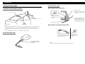
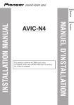
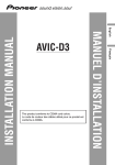
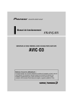
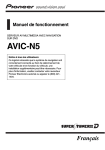
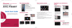
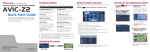
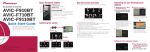
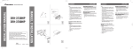
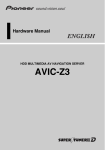
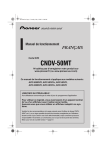
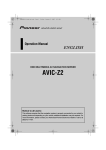
Connecting the Units
GEX-P10XMT
This product conforms to CEMA cord colors.
Printed in Thailand
<CRB2046-A/N> UC
<KKYZX> <04L00000>
INSTALLATION MANUAL
INSTALLATION MANUAL
Note:
• This unit is for vehicles with a 12-volt battery and
negative grounding. Before installing it in a recreational vehicle, truck, or bus, check the battery
voltage.
• To avoid shorts in the electrical system, be sure to
disconnect the ≠ battery cable before beginning
installation.
• Refer to the owner’s manual for details on
connecting the power amp and other units, then
make connections correctly.
• Secure the wiring with cable clamps or adhesive
tape. To protect the wiring, wrap adhesive tape
around wires that lie against metal parts.
• Securely route all wiring so it cannot touch any
moving parts, such as the gear shift, handbrake and
seat rails. Do not route wiring through places that
get hot, such as near the heater outlet. If the insulation of the wiring melts or gets torn, there is a danger of the wiring short-circuiting to the vehicle
body.
Don’t pass the yellow lead through a hole into the
engine compartment to connect to the battery. This
will damage the lead insulation and cause a very
dangerous short.
• Do not shorten any leads. If you do, the protection
circuit may fail to work when it should.
• Never feed power to other equipment by cutting
the insulation of the power supply lead of the unit
and tapping into the lead. The current capacity of
the lead will be exceeded, causing overheating.
• When replacing the fuse, be sure to only use a fuse
of the rating prescribed on the fuse holder.
• To prevent incorrect connection, the input side of
the IP-BUS connector is colored blue, and the output side is colored black. Connect the connectors
of the same
colors correctly.
To safeguard from electromagnetic interference
• In order to prevent interference, set the following
items as far as possible from this unit, its cables or
leads:
– TV antenna and antenna lead
– FM, AM antenna and its lead
– GPS antenna and its lead
In addition route each antenna lead as far as possible from other antenna leads. Do not bind them
together, lay or route them together, or cross them
over each other. Increased interference could lead
to TV reception appearing fuzzy.
• Cords for this product and those for other products
may be different colors even if they have the same
function. When connecting this product to another
product, refer to the manuals supplied with both
products and connect cords that have the same
function.
Connecting the Units
Connecting the power cord and antenna
Antenna Unit
Connecting the system (2)
When connecting this product to the unit, support the data communication functions (e.g.
AVIC-D1, AVIC-N2, AVIC-N1) by both an IP-BUS and XM DATA cable, connect each
equipment as below.
This product
Antenna Input
Navigation system (sold separately) (e.g. AVIC-D1, AVIC-N2, AVIC-N1)
Display unit
Note:
Violet
When combining this product with
AVIC-N1 (sold separately), be sure to
updated with the latest map disc
CNDV-50MT [CNDV-50MTP] (sold
separately) to utilize traffic and data
functionality.
5m (16 ft. 5 in.)
Power Supply
EXTENSION port
Black
Hide-away unit
DATA OUT port
Fuse holder (2 A)
IP-BUS Input
Yellow
To terminal always supplied with power
regardless of ignition switch position.
Red
To electric terminal controlled
by ignition switch (12 V DC) ON/OFF.
Fuse resistor
Black (ground)
To vehicle (metal) body.
This product
To EXTENSION
port
XM DATA cable
Blue
Black
To IP-BUS Input
(Blue)
Black
Blue
3 m (9 ft. 10 in.)
Connecting the system (1)
When using this product with the head unit (or AV head unit) using the IP-BUS only, connect each piece of equipment as below.
This product
IP-BUS cable (supplied)
3 m (9 ft. 10 in.)
Not used.
IP-BUS cable
Note:
When combining this product with Pioneer navigation system
(sold separately), this connection is required.
IP-BUS output
(black)
Black
Blue
3 m (9 ft. 10 in.)
To IP-BUS input (blue)
Head Unit
(sold separately)
IP-BUS cable
(supplied)
IP-BUS input
(blue)
IP-BUS cable
Multi-CD player
(sold separately)
Multi-CD player
(sold separately)
Installation
A Title (English)
Note:
• Before making a final installation of the unit, temporarily connect the wiring to confirm that the connections are correct and the system works properly.
• Use only the parts included with the unit to ensure
proper installation. The use of unauthorized parts
can cause malfunctions.
• Consult with your nearest dealer if installation
requires the drilling of holes or other modifications
of the vehicle.
• Install the unit where it does not get in the driver’s
way and cannot injure the passenger if there is a
sudden stop, like an emergency stop.
• When mounting this unit, make sure none of the
leads are trapped between this unit and the surrounding metalwork or fittings.
• Do not mount this unit near the heater outlet,
where it would be affected by heat, or near the
doors, where rainwater might splash onto it.
• Before drilling any mounting holes always check
behind where you want to drill the holes. Do not
drill into the gas line, brake line, electrical wiring
or other important parts.
• If this unit is installed in the passenger compartment, anchor it securely so it does not break free
while the car is moving, and cause injury or an
accident.
• If this unit is installed under a front seat, make sure
it does not obstruct seat movement. Route all leads
and cords carefully around the sliding mechanism
so they do not get caught or pinched in the mechanism and cause a short circuit.
• When installing this unit, do not stack it with other
products (e.g. do not stack with the hide-away TV
tuner) as there is the possibility of the XM tuner
interferring with the other unit, and causing poor
reception.
• Install the antenna on as flat a place as possible.
• Do not paint the antenna, as this may affect its performance.
• Do not place items such as magnetic cards close to
the antenna because it has a powerful field of magnetism.
• The antenna may be less sensitive when it is snowing.
• When installing the antenna with magnet, be careful not to scratch the vehicle body.
• Be sure to detach the antenna and place inside the
vehicle every time you enter a carwash. If it is left
on the outside it may be knocked off and scratch
the vehicle body.
Installing the Unit
Mounting with Brackets
Tapping screw (4 × 12 mm)
Screw (4 × 6 mm)
Car mat or chassis
Bracket
Drill 2 - 2.5 mm diameter holes.
Installation
Installing the Antenna Unit
Route the antenna cable
Installation using the magnet of antenna
When routing the lead inside the trunk
Waterproof pad
Make sure the waterproof pad
contacts the top of the rubber
packing.
6in. (15.5 cm)
clamper
6in. (15.5 cm)
Clamps
Use clamps to secure the
lead where necessary inside
the vehicle.
Make a U-shaped loop in the
lead outside the rubber
packing to prevent rainwater
from flowing along the lead
into the interior of the vehicle.
Rubber packing
When routing the lead through the top of the door
Note:
• If the antenna is mounted on the vehicle’s roof, it can be installed in positions other than those in the
diagram. To ensure the best reception, mount more than six inches away from the edge of the roof.
• If mounted in an exterior location on the vehicle other than the vehicle’s roof, reception may be
poor.
• Do not install inside the vehicle, as reception will be extremely poor.
Secure the antenna cable
Make a U-shaped loop in the lead
on the outside to prevent rainwater
from flowing along the lead into the
interior of the vehicle.
Secure the antenna cable
with the supplied clamper
around here.
Clamps
Use clamps to secure
the lead where
necessary inside the
vehicle.
Note:
• Secure the antenna cable with the supplied clamper where required.