1
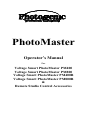
PhotoMaster
Operator’s Manual
For
Voltage Smart PhotoMaster PM400
Voltage Smart PhotoMaster PM800
Voltage Smart PhotoMaster PM400R
Voltage Smart PhotoMaster PM800R
&
Remote Studio Control Accessories
OPERATOR MANUAL FOR POWER SUPPLIES
Voltage Smart PhotoMaster PM400, PM400R,
PM800 & PM800R
Voltage Smart Advantage Light Heads: PA8,
PA8C, PA8D & PA8F
Operator Manual for Infrared Accessories
Thank you for selecting the Photogenic Professional Power Supply
PhotoMaster brand Voltage Smart series. The Voltage Smart
PhotoMaster series incorporates the newest electronic technology
providing improved lighting control, power setting repeatability and
expanded functions. These products are built for the demanding
operational needs of the professional photographer and it is our
expectation that your Power Supply and Power Supply accessories
will provide you with years of dependable service. The Voltage
Smart PhotoMaster models permit use of worldwide voltages and
frequencies. With the new Voltage Smart PhotoMaster “R” models,
optional accessories include infrared remote control.
INTRODUCTION
The Voltage Smart PhotoMaster lighting systems use a power supply
unit and up to four detachable PA8 light heads. Each Light Head
uses a professional plug-in flashtube, 100-watt ESR adjustable quartz
modeling light, and bare bulb capability, both vertically and
horizontally. The Light Heads are fitted with Photogenic’s unique
quick-change system for holding accessories made by Photogenic
Professional. Unlike monolights, light heads can be mounted upside
down.
Before using your new PhotoMaster for the first time, please
read this manual carefully and acquaint yourself with the
controls and features. In this way, you can quickly get the
greatest benefit from your new unit and maintain an efficient
and safe operation.
2
SAFETY PRECAUTIONS
Despite the measures that have been taken to make electronic flash equipment safe,
it must be recognized that high voltages and high temperatures do exist within the
power supply & light heads. Certain precautions must be observed in handling the
unit. Contact with internal high voltage may result in severe injury or death.
1.
2.
3.
4.
5.
6.
7.
8.
9.
Before installing or removing the flashtube and modeling lamp, be sure this
appliance is turned off, cooled and unplugged from AC power source.
Do not touch the glass tubes with bare hands, as normal body salts will shorten
the bulb’s life. Always use a clean cloth or wear gloves to protect your hand
from glass breakage and heat.
Do not defeat the purpose to the three-wire line cord by disconnecting the
ground. Connect to properly functioning and grounded 3-pin receptacles only.
If you are using an extension cord, be sure the cord has an equivalent or greater
rating and has a ground.
Do not insert a screwdriver or other metal objects into the flashtube socket area
or vents. Contact with high voltage may result.
Do not operate this appliance with a frayed or damaged line cord or light head
cable.
Do not attempt to use this appliance if it has been dropped or damaged, until a
qualified service person has serviced it.
Do not operate the unit with a damaged or broken flashtube or modeling lamp.
Do not use flashtubes with broken, cracked or missing glass envelopes. To
prevent damage or injury always use Photogenic specified replacements for the
flashtubes and modeling lamps.
Perform no internal service work on these units. Refer all such service to a
qualified service person or return to the factory. This will provide you safety
and continuation of your warranty.
Do not operate when water is present and/or extreme temperature shifts. If the
unit is stored in hot or below freezing temperatures, allow at least one hour at
room temperatures before using.
PREPARATION AND BASICS
Unpacking and Setup:
Unpack all units carefully to remove all parts from the carton(s). Do not discard or
destroy the packing material until the equipment has been inspected, assembled, and
all parts accounted for.
After unpacking, all parts should be examined for any damage, which may have
been caused by rough handling during shipment. If any damage is detected, contact
the delivering carrier at once. Claim for damage should be made to the delivering
carrier before destroying packing cartons.
3
To set up the lighting system, first mount and secure all light heads to suitable
stands. The stand adapter allows the light head to be mounted on a stand with a 3/8”
to 5/8” post. Be sure to use a stand that is stable and will not tip easily.
The light heads are shipped with the modeling lamp and flashtube not installed.
While installing the modeling lamp and flashtube (with glove or clean cloth to
protect the hand) be certain they are properly inserted and tight to avoid arcing and
failure of the socket contacts during operation. Do not touch the glass tubes with
bare hands, as normal body oils will shorten the bulb’s life. Always use a clean
cloth or wear gloves to protect your hand from glass breakage and heat.
The 7 ½ inch reflector is attached to the PA8 by the “quick-change” mechanism.
Three tabs on the unit grip the ring on the reflector. Finger levers located on the top
of the unit control two of these tabs. To mount the reflector, squeeze the finger
levers towards each other and tilt the reflector past the stationary top-tab, then past
the two tabs that are controlled with the levers. Release the finger levers and make
sure all three tabs are securing the reflector (see illustration below.) All accessory
reflectors and soft boxes are designed for use with this “quick-change” system or
onto this 7-½ inch reflector
Squeeze levers to mount
reflector in locked position.
Punch out hole for
umbrella rod.
Professional plug-in
flashtube.
With power supply’s power switch OFF, attach the line cord to the powerinput connector, located on the back of the PhotoMaster, and connect it to a
grounded wall outlet. Turn the power switch ON. The READY light will
light when the unit has charged to the power level set by the FLASH power
control.
4
HANDLE
FAN
INLET
HEAD
CONNECTORS
AC POWER INLET
SYNC JACK
BREAKER
OUTLET VENTS
REAR VIEW OF PHOTOMASTER
HEAD
CONNECTOR
TOP VIEW
The light head connectors are key-shaped, snap-in type and will only attach
correctly. The plugs must be inserted until the locking snap is heard. Press
the flat metal inset to release. The mating pins are automatically lubricated
during each insertion and withdrawal to greatly extend the life of these
connectors.
5
DIGITAL CONTROL PANEL AND BASIC OPERATION
Power Input:
The power required to operate the Voltage Smart PhotoMaster PM400, PM400R,
PM800, or PM800R is 90 to 250 volts AC, 50 or 60 Hz, 5 Amp. The supplied
power cord has a 125V, 15 Amp rating, 15 ft long, and is detachable. For European
operation, Photogenic can supply a 230V power cord (PLXLC) with a German plug,
rated 90 to 250 volts AC, 50/60 Hz, 10 Amp, 20 ft. Replacement cords or extension
cords rated for less amperage may overheat and should not be used with
PhotoMaster.
Circuit Protection:
Circuit protection automatically protects this appliance from excessive damage due
to circuit or component failure. Operation exceeding the rated cycle of the appliance
may cause the breaker to open. The power supply has an external circuit breaker
and four internal fuses (one for each light head modeling lamp). An additional
thermal protector is located inside the power supply and may open (removing all
power from circuits), if the rated duty cycle is exceeded. The internal thermal
protector may require four minutes to cool down. Simply press the center of the
circuit breaker (located on rear panel of power supply) to reset.
Each light head has an external fuse in the modeling lamp circuit. To replace a
blown light head fuse (power cord must be disconnected), simply unscrew the fuse
holder cap (bottom of unit) and replace the exposed fuse with a new fuse (21731500, 3 Amp, 250V, FB, 5x20mm). If fuses continue to blow, contact your dealer or
qualified service person. (See specification section for fuses replacements). If the
modeling lamp will not light, switch head connections on the power supply. If no
modeling lamps will light on a particular power supply head connector, then the
power supply internal modeling lamp fuse has blown. Return power supply to
service for repair. Never, never replace a fuse with one of higher current rating.
This is a non-warranty repair.
Power-Up display sequence.
The processor will search the unit for functions that have been activated from the
last time the light was used. As this search is done the first display reads “8888”.
Next in the search sequence is AC and Hertz and you will see 50 or 60 displayed. If
Auto-Bracketing is active you will see =br= followed by the High “H” setting and
then the Low “L” setting (see Auto-Bracketing, page 10.) The final standard
sequence displays the unit number designated for the power supply pack, 1 through
9. When the search cycle is complete, the display will then show the setting for
flash watt seconds.
See Advanced Features & Diagnostic Display Codes.
6
Functional Operation
Voltage Smart PhotoMaster
PM400, PM400R, PM800 & PM800R
Power Switch:
The power switch controls the AC power to both the modeling and flash circuits.
You have the option to turn-off the modeling circuit independently by pressing the
Full On/Off button.
A
B
F
G
H
C
D
E
I
Flash Power:
When the power is turned on the red Flash LED (A) is illuminated. You adjust the
Flash power settings by pressing the 1/2 or 1/10 f-stops UP/DOWN arrow buttons.
The watt second settings will be displayed. (If the adjust button (E) is pressed again
the modeling circuit and yellow Watts LED (B) will be turned on.)
Ready Light:
The Voltage Smart PhotoMaster PM800 & PM800R models are fully charged when
the green READY lamp is on. Lowest power (25 ws) setting charge time is a
maximum of .8 seconds and at full power charge (800 ws) time is a maximum of 3
seconds. The unit may be flashed before fully charged. When adjusting flash power
settings downward, the units will bleed stored power until the lowered power setting
is reached. The green READY light will then be re-illuminated.
The Voltage Smart PhotoMaster PM400 & PM400R models are fully charged when
the green READY lamp is on. Lowest power (12.5 ws) setting charge time is a
maximum of .5 seconds and at full power charge (400 ws) time is a maximum of 1.5
seconds. The unit may be flashed before fully charged. When adjusting flash power
settings downward, the units will bleed stored power until the lowered power setting
is reached. The green READY light will then be re-illuminated.
7
Modeling Lights:
The modeling lights have three symmetrical modes of operation (NOT independent):
1. MANUAL adjusts the modeling lamp intensity using the 1/2 or 1/10 f-stops
UP/DOWN arrow buttons. Press the manual ADJUST button (F) to turn the
MODEL yellow LED (B) on. Pressing the manual ADJUST button (F) a second
time will change the mode to flash adjustment and is indicated by the illuminated
red Flash LED (A).
2. TRACK mode (Proportional modeling) causes the modeling lamp intensity to
track the FLASH setting. The modeling lamp may be re-set to full intensity at any
FLASH value, by simply pressing the TRACK/SET button (G) a second time, with
the FLASH already set to desired watt-seconds. This setting is retained when the
user returns from another mode.
3. FULL ON/OFF is exactly what it says. Press the FULL ON/OFF button (C) to
turn the modeling lamp OFF (LED off) or ON (LED on).
Note: All current mode settings are retained, even after the power is turned off.
4. Each light head modeling lamp can also be turned on/off with rear switch on the
respective light head.
Test Function:
The TEST Flash button is pressed to fire the flashtube for test purposes, to re-set
after a misfire or to dump stored power when moving to a lower watt second level.
Ratio Light Head Flash Power:
The two left light heads (looking at the power supply front) can have a 3:1 flash
power ratio to the two right light heads. There are four flash capacitors, of equal
value, inside the power supply. All four light heads share the total flash power
setting. The RATIO function simply connects the two left light heads to three flash
capacitors and the two right light heads to one flash capacitor. [Note that if all four
light heads are used, without ratio, each would deliver 1/4 of the flash power setting.
If all four light heads are used, with ratio, the two left light heads would each deliver
3/8 of the flash setting, and the two right light heads would each deliver 1/8 of the
flash setting (3:1 ratio). If using three heads (two left and one right), the two left
heads would each deliver 3/8 of setting and the right head would deliver 1/4 of the
setting. ] The RATIO feature can be turned ON (LED on) or OFF (LED off) with
the RATIO/Auto Bracket button.
Diagnostic Display Codes:
In addition to internal thermal protection, the microcomputer software monitors the
AC line power and flash power consumption to prevent catastrophic damage to your
new PhotoMaster units. The following error codes may be displayed:
“Er-0” message means that an AC line power frequency problem has occurred.
This could be internal or in the power cable or outlet at the location. Try turning
the main power off, wait for 5 seconds and turn power back on.
“Er-1” message means that an AC line power voltage problem has occurred. This
could be internal or can happen with voltage spikes and voltage fall-off in the
location AC line power. Try turning the main power off, wait for 5 seconds and
turn power back on.
8
“Er-3” message means over heating has occurred. This could be internal or by
exceeding the recommended flash frequency. (See flash rate chart) Once “Er-3”
is displayed a “COOL” mode is activated to cool off internal components,
preventing damage. This usually is caused by too many quick-discharges,
resulting in the overheating of the unit’s circuits. (See flash rate chart) The unit
remains in this COOL mode for approximately 4 minutes. This is an
electronically timed period and turning the power OFF will not shorten this
COOL period.
Synchronization and Triggering:
Triggering is accomplished by using a built-in photoslave or a trigger cable
from the power supply to the camera shutter contacts of ”X” or “zero”
delay. Other units in the system are then triggered by photoslave operation.
It is suggested that all walls and ceiling be painted either white or light
neutral colors for most reliable photoslave operation.
After the trigger cord is properly connected, check the synchronization with
the camera. Adjust a light head to same height as the camera lens and face
the light into the lens. The lens aperture should be open to its fullest extent
and set on “X” or “zero” delay. Remove the camera back. It is best to
perform this test with the modeling lamps turned off.
While looking at the lens through the back of the camera, operate the
shutter. A few sheets of white paper in front of the lens will cut down the
brilliance of the flash and aid in making the observation. The flash of the
light should then appear as a circle the same size as the aperture. If the
circle is flattened on the sides, or if no light appears through the lens, the
shutter is not synchronized. If the shutter appears not to be synchronized, a
reputable camera repair shop should check the shutter contacts.
The sync polarity is Positive on center pin of cable connectors (Photogenic
part PLTC, and defined in ISO 518.)
Sync voltage is 12 vdc (Spec. = less than 24 vdc per ISO 10330:1992E, and
greater than 9 vdc for Wein photo slave at 10 microampere drain.) Internal
240 ohm discharge limit, with 68 k ohms continuous limit.
Sync signal = negative pulse, 10 microseconds or longer, from sync voltage
to 1.6 vdc or less (per ISO 518.)
Photocell/Photo Slave:
The sensor is built into the power supply and can be shut off by plugging in
the sync. cord.
9
Flash Power Bracketing:
Bracketing refers to taking up to three (3) exposures in a sequence with
different flash intensities, either additional watt seconds or fewer watt
seconds, from the displayed or selected “primary” base intensity. The
PhotoMaster enables you to set the base flash power and then one high and
one low bracketing value. Once the setting(s) have been pre-set, a sequence
of power levels will automatically occur as you take the exposures. If you
wish to only bracket up from the primary, set a HIGH value and leave the
LOW value at “0”. If you wish to only bracket down from the primary, set
the HIGH value at “0” and set a LOW value.
The 3-exposure bracketing sequence is:
1. Primary power setting.
2. Higher power pre-set.
3. Lower pre-set.
The 2-exposure bracketing sequence is:
1. Primary power setting.
2. Either Higher or Lower (skips the “0” settings)
To set or change the Auto-Bracketing settings:
1. Press the Auto-Bracketing button 3 times. This will cause
the display to read “br”, then H. .0
2. Press the small up or down (1/10) button to set the HIGH
value. The values can be set at zero “0” to “1.5” f-stops above
the primary power setting.
3. Press the large up (1/2) button once. This will cause the
display to read “L. .0
4. Press the small down or up (1/10) button to set the LOW
value. The values can be set at zero “0” to “1.5” f-stops below
the primary power setting.
5. Press the AUTO-BRACKET button to save these pre-sets.
To turn off the Auto-Bracketing settings:
Setting both the HIGH and the LOW values at zero “0” will turn off the
Auto-Bracket feature.
Note: The auto-bracketing settings are retained and sequenced until the
feature is manually turned off. If the primary power setting is changed the
Auto-Bracketing feature will continue to sequence using the pre-set HIGH
and LOW values from the new primary level.
(This bracketing feature is limited by the 6 f-stop range of total watt
seconds available.)
10
OPERATIONAL PARAMETERS
Voltage Smart PhotoMaster PM400R & PM400R
Flashing Rate:
The unit recharges quickly, as indicated by the READY light on the control panel.
A quick series of flashes can be obtained within the limits of the recharge time.
Continuous rapid flashing, however, can overheat and damage the flashtube and
internal parts. The maximum recommended rate of flashing would depend upon the
power level being used and the amount of operation time. Use the following chart to
serve as a guide for the maximum rate to use in your situation.
Power Level
Full
1/2
1/4
Operating
Time
Continuous
6.8 Minutes
2 Minutes
Continuous
6.8 Minutes
2 Minutes
Continuous
Sec. Between
Flashes.
8.3
4
4
3.3
2
1
2
Number of
Flashes
Continuous
100
60
Continuous
200
116
Continuous
Exposure Information:
The following charts give the BCPS output for various umbrellas and reflectors.
Coverage angle is given in degrees.
Umbrella
Coverage
Full Power
½
¼
1/8
1/16
1/32
32 inch
120 degree
45 inch
120 degree
60 inch
120 degree
4400
2200
1100
550
275
137
4466
2233
1117
558
279
140
4466
2233
1117
558
279
140
Reflector
Diameter
Coverage
None
360°
7 ½”
35°
14”
40°
16”
60°
20”
65°
24”
145°
Full Power
½
¼
1/8
1/16
1/32
GN@ASA100/10’
1866
933
467
233
117
58
88
20000
10000
5000
2500
1250
625
292
14000
7000
3500
1750
875
438
244
18666
9333
4667
2333
1167
583
280
13066
6533
3267
1633
817
408
236
3360
1680
840
420
210
105
120
11
SPECIFICATIONS
Voltage Smart PhotoMaster PM400 & PM400R
General:
Flash Power….........................................……….. 12.5 to 400 watt-seconds.
Maximum (6 f-stops)
Flash Duration….........................................…….. 1/1625 second at Full
1/800 second at 1/32
Reciprocity………………………………………. Excellent, no filters required
Recycling time…..........................................……. 0.5 to 1.5 seconds @ full
Power Control…............................................…… Full to 1/32 range.
(6 f-stops)
0.1 f-stop resolution.
Modeling Light Power ................................…… . 100 Watt Quartz, ESR
Modeling Light Control ...............................…… Full to 1/32 range.
0.1 f-stop resolution.
Line voltage regulated.
Triggering ....................................................……. Built in Photoslave.
Push to Test button.
Synchronization Jack.
12 volt isolated.
Main Supply …………..……………………….. 90-250 VAC, 50/60 Hz, 3.5 A.
Consumption …………........................................ 0.2 amps idling,
5.5 amps charging.
Voltage Stabilization …....................................... Plus or minus 0.05 f-stop.
Packaging PM400, PM400R................................ Tough, Kydex plastic case.
Packaging PA8…….............................................. Extruded Aluminum case.
Weight PM400, PM400R…................................ 6.2 pounds.
Weight PA8…..................................................... 3.5 pounds, (w flash tube).
Dimensions PM400, PM400R……..................... 9”H x 9.5”W x 6”D
PA8 (housing only)……….…………4.5”H x 4.5”W x 6”D
Flashtubes and Modeling Lamps:
Flashtube ..................................................……… Plug-in style, use
Photogenic’s C4-19, C4-19C, C4-19D, C4-19F, L4-19 or L4-19C.
Modeling Lamp (each PA8)....................…….
100-Watt Quartz Halogen, ESR.
Overload Protection PM400, PM400R.......…... Circuit Breaker, 12 Amp.
Overload Protection Fuse PA8..................5 mm X 20 mm, 3 Amp, fast blow.
12
OPERATIONAL PARAMETERS
Voltage Smart PhotoMaster PM800, PM800R
Flashing Rate:
The unit recharges quickly, as indicated by the READY light on the control panel.
A quick series of flashes can be obtained within the limits of the recharge time.
Continuous rapid flashing, however, can overheat and damage the flashtube and
internal parts. The maximum recommended rate of flashing would depend upon the
power level being used and the amount of operation time. Use the following chart to
serve as a guide for the maximum rate to use in your situation.
Power Level
Full
1/2
1/4
Operating
Time
Continuous
13 Minutes
2.7 Minutes
Continuous
6.8 Minutes
2 Minutes
Continuous
Sec. Between
Flashes.
Number of
Flashes
15
10
5
8
4
2
3.3
Continuous
81
32
Continuous
100
58
Continuous
Exposure Information:
The following charts give the BCPS output for various umbrellas and reflectors.
Coverage angle is given in degrees.
Umbrella
Coverage
Full Power
½
¼
1/8
1/16
1/32
32 inch
120 degree
45 inch
120 degree
60 inch
120 degree
8800
4400
2200
1100
550
275
8933
4466
2233
1117
558
279
8933
4466
2233
1117
558
279
Reflector
Diameter
Coverage
None
360°
7 ½”
35°
14”
40°
16”
60°
20”
65°
24”
145°
Full Power
½
¼
1/8
1/16
1/32
GN@ASA100/10’
3733
1866
933
467
233
117
128
40000
20000
10000
5000
2500
1250
412
28000
14000
7000
3500
1750
875
344
37333
18666
9333
4667
2333
1167
396
26133
13066
6533
3267
1633
817
332
6720
3360
1680
840
420
210
168
13
SPECIFICATIONS
Voltage Smart PhotoMaster PM800, PM800R
General:
Flash Power….........................................……….. 25 to 800 watt-seconds.
Maximum (6 f-stops)
Flash Duration….........................................…….. 1/962 second at Full
1/431 second at 1/32
Reciprocity………………………………………. Excellent, no filters required
Recycling time…..........................................……. 0.8 to 3 seconds @ full
Power Control…............................................…… Full to 1/32 range.
(6 f-stops)
0.1 f-stop resolution.
Modeling Light Power ................................…… . 100 Watt Quartz, ESR
Modeling Light Control ...............................…… Full to 1/32 range.
0.1 f-stop resolution.
Line voltage regulated.
Triggering ....................................................……. Built in Photo slave.
Push to Test button.
Synchronization Jack.
12 volt isolated.
Main Supply …………..……………………….. 90-250 VAC, 50/60 Hz, 3.5 A.
Consumption …………........................................ 0.2 amps idling,
5.5 amps charging.
Voltage Stabilization …....................................... Plus or minus 0.05 f-stop.
Packaging PM800, PM800R................................ Tough, Kydex plastic case.
Packaging PA8…….............................................. Extruded Aluminum case.
Weight PM800, PM800R…................................ 6.2 pounds.
Weight PA8…..................................................... 3.5 pounds, (w flash tube).
Dimensions PM400, PM400R……..................... 9”H x 9.5”W x 6”D
PA8 (housing only)……….…………4.5”H x 4.5”W x 6”D
Flashtubes and Modeling Lamps:
Flashtube ..................................................……… Plug-in style, use
Photogenic’s C4-19, C4-19C, C4-19D, C4-19F, L4-19 or L4-19C.
Modeling Lamp (each PA8)......................……. 100-Watt Quartz Halogen, ESR.
Overload Protection PM400, PM400R.......…... Circuit Breaker, 12 Amp.
Overload Protection Fuse PA8..................5 mm X 20 mm, 3 Amp, fast blow.
14
ADVANCED POWERLIGHT FEATURES.
Voltage Smart PhotoMaster PM400, PM400R, PM800 & PM800R
Automatic Discharge
Each time the AC line power is disconnected or switched off, the unit will
automatically flash-dump most of the stored power, and then discharge by resistor
the remainder of the stored power. This removes all of the flash capacitor charge to
prolong the life of the unit and is a much safer condition for storage, for
transporting, and replacement of flash tube or modeling lamp. Even if the flash tube
is defective or absent, the internal resistor will discharge all power within 30
seconds after the unit is turned off. This is a feature, over which the user has no
control.
Unit Number Assignment
This feature allows the user to assign a UNIT NUMBER (1 to 9) to each
PhotoMaster in the studio. The UNIT NUMBER is necessary when INFRARED
remote control is used with the PM400R or PM800R models (see accessories.)
To assign a UNIT NUMBER, the startup sequence will need to be interrupted. Turn
PhotoMaster AC power OFF. With the unit OFF press and hold the ½ stop “UP”
button then turn the power switch to ON, continue holding the ½ stop button until
the display reads “ir” then release the button. The Digital display should read “ir”
when you press and release the ½ UP button again, and the display will then read
“Un - 1”, or some number 1 to 9. To change the UNIT number, press and release
the 1/10 UP/DOWN arrow buttons until the desired number is displayed. To save
and close the assignment feature and save the UNIT number, press and release the
1/2 UP arrow button again. This allows the startup sequence to finish and save the
new settings. Each “R” unit’s default unit number is set at “Un - 1”. You must reset the unit number with the 1/10 adjustment buttons, or the default “Un 1” will
automatically be assigned.
Wireless Setup.
The “R” units are pre-set for Infrared wireless operations at the factory and no
adjustments are necessary for operation. See next section.
15
Advanced Series Accessories.
Voltage Smart PhotoMaster PM400R & PM800R
PLIRC-1 Infrared remote controller.
Similar to TV, VCR, DTV universal remote controllers, the PLIRC-1 can control up
to nine (9) PhotoMasters with individual settings. If several PhotoMasters are used
with identical settings, the same unit number can be assigned to them. This will
expand the total number of lights that can be controlled with the PLIRC-1. All panel
button controls are available, plus STANDBY.
Photogenic’s PowerLight
monolights may be mixed into a studio set-up with PhotoMasters and controlled
with the same PLIRC-1 remote.
Unit Number Assignment
This feature allows the user to assign a UNIT NUMBER (1 to 9) to each
PhotoMaster power supply in the studio. The UNIT NUMBER is necessary when
INFRARED remote control is used.
To assign a UNIT NUMBER, the startup sequence will need to be interrupted. Turn
PhotoMaster AC power OFF. With the unit OFF press and hold the 1/2 “UP” button
and then turn the power switch to ON. The display should read “un#” (# being some
number 1 through 9.). To change the UNIT number, press and release the 1/10
UP/DOWN arrow buttons until the desired number is displayed. To save and close
the assignment feature and saving the UNIT number, press and release the 1/2 “UP”
arrow button again. This allows the startup sequence to finish and save the new
settings. Each PhotoMaster default unit number is set at “Un - 1”.
PLIRC-1 Use
Select a Unit Number on one of the top ten buttons, and then control the
PhotoMaster with the lower buttons, observing the PhotoMaster digital display for
the changes. All PhotoMaster front panel controls/functions (except LED displays)
are available on the remote and operate in exactly the same way. Refer to pages 7
and 8 for operational instructions for each button, feature and function.
The All button, under Unit Number, transmits the changes to all active
PhotoMasters. This enables the photographer to raise or lower flash or model levels
on several PhotoMaster power packs, without the laborious task of changing them
individually.
STANDBY lets the photographer put the PhotoMaster into a standby state to stop
public photographers from slaving the units at a wedding, or some PhotoMaster
studio units can be put in standby when not required for a shot. The infrared control
can easily reach to 100 feet, indoors.
16
General Trouble Shooting
COMMON PROBLEMS AND CAUSES
Unit does not charge. Probable causes:
1. Circuit breaker tripped. (Depress breaker button, rear of unit.)
2. No line power to unit. (Check line cord and outlet. If unit was being
heavily used, wait 5 minutes for internal thermal protector to reset.)
Modeling light does not turn on. Probable causes:
1. Lamp turned off. (Press FULL ON/OFF button, check PA8 switch.)
2. Lamp burned out. (Inspect and replace, when cool. See SERVICE
section of this manual)
3. Internal fuse blown (inside power supply), caused by shorted
modeling lamp. (Factory service required.)
4. External fuse blown on PA8. (Inspect and replace.)
Light flashes by itself without apparent reason. Probable causes:
1. Defective trigger cord, or trigger cord incorrectly polarized.
2. Bright light falling on photo slave.
3. Poor connection in line cord.
4. Reverse connection on trigger cord connection at camera.
5. Some radio slaves will cause interference.
Consult slave
manufacturer.
Trigger cord will not flash unit, but charge indicator shows that the system has
charged. Probable causes:
1. Defective trigger cord. Try TEST button.
2. Internal failure. Try TEST button.
Defective flashtube:
1. Turn unit OFF. Wait until cool, and then replace flashtube.
(See SERVICE section of this manual)
Infrared not working. Probable causes:
1. When using the Hand-Held controller, press the unit number on the
keypad before pressing any adjustment buttons.
2. Point remote directly at PhotoMaster control panel from about five
feet distance.
3. Check 9 volt battery inside remote.
4. Unit number on controller must agree with unit number on
PhotoMaster. Try the All key before testing.
17
Limited PhotoMaster Warranty
Photogenic warranties the “standard line” products are free from defects in
material and workmanship of the PhotoMaster PM400, PM400R, PM800,
PM800R and PA8 units for a period of three years, from date of
manufacture. At our choice, we will repair or replace any of the above that
is deemed to be defective. This warranty does not cover damages caused by
shipping, product abuse or use other than the intended photographic
applications.
Any product modifications will render this warranty void. Use of other
manufacture’s accessories (including flash tubes and modeling lamps),
which restrict normal or intended operation (especially venting airflow on
the PA8), may cause damage and will void this warranty.
SERVICE
The photographer should not attempt to make internal repairs.
Consult a dealer for an authorized Photogenic Professional Lighting
service agent.
This will provide you safety, insure proper
operational functions and provide continuation of your warranty.
The technicians find in helpful to have the complete unit to better
troubleshoot and evaluate any problems. This includes the light unit,
the power cord, light heads, head cables, flash tubes and all modeling
lamps.
For replacing the flashtube or modeling lamp, follow the directions
and specifications given earlier in this manual in the setup section.
Before removing the old tubes or installing new tubes, always
unplug your PhotoMaster to discharge the stored energy. Wait
approximately 30 seconds for the main capacitors to deplete any
residual stored wattage. Never place your fingers or any metal
objects into the flash or modeling sockets. Contact with high voltage
may result.
18
PA8 QUICK CHANGE ACCESSORIES
REFLECTORS:
PL3R ------3” Shallow Background reflector rotates to control light for high key and
back lighting.
PL3RV-----3” Veil Slotted Background reflector for veil and burst-lighting
PL5R-------5” Deep Conical Background reflector.
PL7R-------7 ½” Standard high grain reflector. 35-degree coverage.
PL14R-----14” Parabolic for portraits, feathering, flood and fill lighting.
45-degree coverage.
PL16R-----16” Parabolic for portraits, feathering, flood and fill lighting.
60-degree coverage.
PL18R-----18” Parabolic for soft illumination and flood lighting.
125-degree coverage.
PL20R-----20” Parabolic for portraits, feathering, flood and fill lighting.
65-degree coverage.
PL24R-----24” Parabolic for soft illumination and flood lighting.
145-degree coverage.
Additional Photogenic Light-Shaping Accessory items and Kits.
Grids.
Snoots.
Soft Boxes.
Barndoor Sets.
Tilting Handle.
Scrim & Gel rings.
Eclipse Umbrellas.
Counter-Balance weights.
Contact your local dealer for these and other Professional Photographic products by:
19
Photogenic Professional Lighting
1268 Humbracht Circle
Bartlett, Illinois 60103
www.Photogenicpro.com
Telephone: 630-830-2500 Fax: 630-830-2525
016497-00V2-04
20