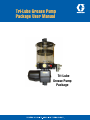
1
Tri-Lube Grease Pump
Package User Manual
Tri-Lube
Grease Pump
Package
Tri-Lube Grease Pump Package User Manual
L42255
TABLE OF CONTENTS
SECTION/PARAGRAPH
PAGE
1.0 Introduction
1.1
General.................................................................... 1-1
1.2
Safety Instructions............................................... 1-1
1.3
Description.............................................................. 1-1
1.4Operation................................................................. 1-2
2.0 Installation
2.1 Mounting.................................................................. 2-1
2.2 Wiring........................................................................ 2-1
2.3 Filling Reservoir..................................................... 2-2
2.4 Purging Air from Pump........................................... 2-2
2.5 Adding Pump elements........................................... 2-3
2.6 Pump Adjustments.................................................. 2-3
SECTION/PARAGRAPH
PAGE
3.0 Service and Repair
3.1Required Tools........................................................ 3-1
3.2Replacing Cover, Ll & FollowER........................... 3-1
3.3Replacing Reservoir............................................... 3-2
3.4Replacing Eccentric Shaft Bearing..................... 3-2
3.5Replacing Cam Assembly........................................ 3-2
3.6Replacing DC Gearmotor....................................... 3-3
3.7Replacing AC Motor................................................ 3-4
4.0
5.0
Parts Lists .............................................4-1 thru 4-3
Troubleshooting .................................................. 5-1
LIST OF ILLUSTRATIONS
NUMBER
TITLE
PAGE
1-1PUMP OPERATION...................................................... 1-2
2-1PUMP DIMENSIONS................................................... 2-1
2-2ELECTRICAL DIAGRAMS............................................. 2-1
2-3TYPICAL PUMP PACKAGE........................................... 2-2
2-4ADD PUMP ELEMENTS............................................... 2-2
2-5RELIEF VALVE ADJUSTMENT....................................... 2-3
2-6OUTPUT ADJUSTMENT............................................... 2-3
3-1RESERVOIR COVER.................................................... 3-1
3-2RESERVOIR & FOLLOWER.......................................... 3-1
3-3RESERVOIR & PADDLE............................................... 3-2
3-4RESERVOIR & BEARING.............................................. 3-2
NUMBER
TITLE
PAGE
3-5ECCENTRIC................................................................ 3-2
3-6
DC MOTOR COVER..................................................... 3-3
3-7
DC MOTOR LEADS..................................................... 3-3
3-8
MOTOR ATTACH SCREWS........................................... 3-3
3-9PUMP DISASSEMBLED............................................... 3-3
3-10AC MOTOR & REDUCER............................................. 3-4
3-11AC MOTOR................................................................. 3-4
4-1
DC PUMP PARTS........................................................ 4-1
4-2AC PUMP PARTS........................................................ 4-2
4-3
11 LB RESERVOIR PARTS........................................... 4-3
LIST OF TABLES
NUMBERDESCRIPTION
PAGE
2-1OUTPUT ADJUSTMENT............................................... 2-3
4-1
DC PUMP PARTS LIST................................................ 4-1
NUMBERDESCRIPTION
PAGE
4-2AC PUMP PARTS LIST................................................ 4-2
4-3
11 LB RES. PARTS LIST.............................................. 4-3
Tri-Lube Grease Pump Package User Manual
L42255
OPERATION AND SERVICE INSTRUCTIONS
SECTION 1
INTRODUCTION
1.1 GENERAL.........................................................................................1-1
1.2 SAFETY INSTRUCTIONS...................................................................1-1
1.3 DESCRIPTION...................................................................................1-1
1.4OPERATION......................................................................................1-2
1.1
GENERAL
1.1.1This User Manual is intended to familiarize the user with the Tri-Lube grease pump and its various features. It contains important information for safe, correct and economical operation of the grease pump. Following the instructions will help avoid hazards, reduce downtime and repair costs, increase the reliability and prolong the service life of the entire system.
1.1.2This User Manual must be read and used by those who will work with the complete lubrication system.
1.1.3Other useful Graco/Trabon Bulletins are:
a. Bulletin 40000 – Series Progressive System
Installation Guide.
b. Bulletin 30103 – How to Remove Air from a Series
Progressive System.
c. Bulletin 30101 – How to locate Blockage in a Series
Progressive System.
1.2
SAFETY INSTRUCTIONS
a. Read all of the applicable instructions before
operating your lubrication system.
b. Keep all operating instructions near system for
future reference.
c. Incorrect use or unauthorized system changes may
result in bearing damage caused by under or over
lubrication.
d. Any existing safety equipment must not be modified
when attaching the lubrication pump and system to
the machine.
e. If any safety equipment is removed to allow
mounting of the lubrication pump or system, it
must be re-assembled prior to machine and/or
lubrication system operation.
f.
Keep lubrication system away from any high heat
source.
g. Disconnect and lock out electrical power source
before attempting any repairs to the Tri-Lube Pump
Package.
h. Use only original replacement parts.
1-1
1-1
Tri-Lube Grease Pump Package User Manual
L42255
1.3 DESCRIPTION
1.4 OPERATION
1.3.1 All Tri-Lube Pump Packages consist of the following components:
1.4.1 Figure 1-1 shows the general relationship of the pump element and the drive eccentric. The following steps outline the operating sequence:
a. A reservoir for holding the lubricant. Reservoirs are
cylindrical in shape and are made from transparent
plastic or metal depending on the specific model.
Each reservoir is equipped with a low level switch
activated by the follower assembly and a rotating
paddle to assist priming of the pump.
a. Grease in the reservoir keeps the pump body full
during normal operation and maintains a head
pressure to accomplish two objectives.
b. A pump element is available with either a fixed or
adjustable output. All pump elements are equipped
with an adjustable relief valve that relieves to
atmosphere. A second or third pump element can be
added in the field to supply additional output volume
or additional lube points where required.
c. A gearmotor (12 or 24 VDC) or a motor and gear
reducer (115 or 230 VAC, 1 ph, or 230/460 VAC, 3
ph) which drives the pump.
•
Provide constant lubrication to the moving
pump components.
•
Supply lubricant to the piston chamber in the
pump cylinder.
b. A rotating cam (Item 1) forces the pump piston
(Item 2) forward displacing lubricant from the pump
cylinder, past an internal discharge check valve and
out of the pump outlet.
c. As the cam (Item 1) continues to rotate, the pullback ring (Item 3) pulls the pump piston (Item
2) back to the prime position allowing grease to
re-prime the piston chamber for the next stroke.
Also attached to the eccentric shaft is a paddle (not
shown) with an angled surface that forces grease
into the pump chamber as it rotates and also aids
in dispersing any small air pockets that might be
present in the grease.
d. A pump body which houses the pump drive
eccentric and to which all other components are
attached.
Fixed Pump Element
1
2
3
Lube
Outlet
1
3
2
Figure 1-1
1-2
Tri-Lube Grease Pump Package User Manual
L42255
OPERATION AND SERVICE INSTRUCTIONS
SECTION 2
INSTALLATION
2.1 MOUNTING......................................................................................2-1
2.2 WIRING............................................................................................2-1
2.3FILLING RESERVOIR.........................................................................2-2
2.4PURGING AIR FROM PUMP...............................................................2-2
2.5ADDING PUMP ELEMENTS...............................................................2-3
2.6PUMP ADJUSTMENTS......................................................................2-3
2.1
MOUNTING THE PUMP
2.1.1 The pump should be mounted in a vertical position with the reservoir at the top and in a protected location, but where it is accessible for filling and routine maintenance.
2.1.2 The pump is mounted using two 5/16” or two 8 mm bolts (furnished by user) that pass through the mounting feet on the pump body. The mounting bolt length will depend on the thickness of the mounting surface and whether the holes are to be tapped for the bolts or locked in place with nuts and washers. Mounting dimensions are shown in Figure 2-1
2.2
WIRING THE PUMP
2.2.1 Electrical connections are shown in Figure 2-2
2.2.2 Wiring to the AC motors should be 16 AWG stranded wire with insulation rated for 300 V max and 105ºC.
2.2.3 The DC pump motors and all low level switches may be wired with 18 AWG stranded wire cable.
DC Motor, Front View
DC Motor, Side View
Figure 2-2b(AC)
Cantoni & ABB Motors
FAN
CAPACITOR
L1
U2
Z1
L2
Z2
U1
GND
Figure 2-2c (DC)
Moto Technica 1ph Motors
W2
AC Motor, Front View
U1
COMMON
NC
Top View, DC and AC
FAN
SHAFT
Figure 2-2d (AC & DC)
2-1
V2
AC Motor, Side View
Figure 2-2a (DC)
Figure 2-1
U2
LOW LEVEL SWITCH WIRING SCHEMATIC
Figure 2-2
V1
W1
Tri-Lube Grease Pump Package User Manual
L42255
2.3 FILLING THE RESERVOIR
2.3.1 The reservoir should be filled with clean air free grease of the type recommended by the machine builder and having an NLGI grade number consistent with the ambient operating temperature of the equipment (grease must be pumpable at the lowest anticipated operating temperature).
CAUTION
Do not fill the reservoir with grease heavier than NLGI #2. For temperatures below -5OF (-20OC), use NLGI #1 or lighter grease.
2.3.2Filling is accomplished by connecting a suitable transfer pump to the fill fitting in the front of the pump housing (See Figure 2-3). Before connecting the transfer pump, make sure that both the lube fitting and the coupler are clean and that the hose and transfer pump are full of clean grease that is free of air.
2.3.4For subsequent re-filling, unless the reservoir has been allowed to run dry or air was pumped into the reservoir, it will not be necessary to remove the yellow plug or fill above the vent hole.
2.4
PURGING THE PUMP AND SYSTEM
OF AIR
2.4.1Operate the pump with the main line disconnected until grease free of air is seen at the pump outlet.
2.4.2Fill and purge system lines and divider valves following the procedures outlined in Trabon Bulletin L30103.
2.4.3Once all lines and dividers have been purged free of air, reconnect pump to mainline.
1
3
Vent Hole
2
Figure 2-4a
Fill Fitting
Pump Position
Plug
Figure 2-3
2.3.3 For the initial filling, or if the reservoir has been allowed to run dry, removing one of the pump position yellow plugs from the pump body will facilitate expelling air from the body and reservoir. Slowly start to fill the reservoir until grease free of air flows from the open pump position. At this point, stop the transfer pump and re-install the yellow plug. After the plug is installed, fill slowly until the follower seal is slightly above the vent hole in the reservoir tube. This will allow air remaining below the follower to escape. When grease free of air is seen at the vent, stop filling.
Figure 2-4b
3
4
Figure 2-4c
Figure 2-4
2-2
Tri-Lube Grease Pump Package User Manual
2.5
ADDING PUMP ELEMENTS
CAUTION
To avoid personal injury or severe internal damage to
the drive-train, or pump element, these procedures
must be followed carefully.
2.5.1 L42255
2.6
PUMP ADJUSTMENTS
2.6.1
Adjusting the Relief Valve. Each pumping element incorporates an adjustable relief valve to protect the system against overpressure. The relief setting can be adjusted by loosening the locking nut (1) (See Figure 2-5) and turning the cap clockwise to increase the relief pressure, and counterclockwise to decrease the relief pressure, as required by the system application.
Disconnect power to the pump motor.
2.5.2 Remove sealing plug 1 (figure 2-4a).
CAUTION
2.5.3Pull out pump piston 2 until it extends approximately 1-1/8” (29 mm) from end of cylinder to end of mushroom head.
2.5.4
Insert element into housing at approximately a 15 degree angle as shown in figure 2-4b.
NOTE: If pump is full of grease, it will be necessary
to clear a path through the grease using a clean
screwdriver.
2.5.5Rotate element down (figure 2-4c) engaging mushroom head between cam 3 and retracting ring 4.
Do not adjust above 2900 psi (200 bar) for DC pumps
or 5075 psi (350 bar) for AC pumps as pump or motor
damage may result.
2.6.2
Pump Output Adjustment. The nominal delivery rate of the pumping element can be adjusted by loosening the locking nut (1) (See Figure 2-6) and rotating the adjustment screw (2)clockwise to reduce delivery, or counterclockwise to increase delivery of the lubricant. The output adjustment table describes the equivalent outputs that can be obtained by varying the distance “A” of the adjustment screw. (See Table 1)
2.5.6Tighten element 18-22 fl-lbs (25-30 N-m). Do not over torque as housing threads will be stripped.
2.5.7Fill reservoir with clean grease (See Section 2-3) and run pump for 1 minute to check for grease output. If none is seen, it could indicate that the element was not properly installed.
Figure 2-6
Figure 2-5
2-3
Tri-Lube Grease Pump Package User Manual
L42255
2-4 (Blank)
Tri-Lube Grease Pump Package User Manual
L42255
OPERATION AND SERVICE INSTRUCTIONS
SECTION 3
SERVICE AND REPAIR
3.1REQUIRED TOOLS............................................................................3-1
3.2REPLACING COVER, LOW LEVEL & FOLLOWER.................................3-1
3.3REPLACEMENT RESERVOIR..............................................................3-2
3.4REPLACING ECCENTRIC SHAFT BEARING.........................................3-2
3.5REPLACING ECCENTRIC & PISTON RETRACT RING............................3-2
3.6REPLACING DC GEARMOTOR...........................................................3-3
3.7REPLACING AC MOTOR....................................................................3-4
3.1
REQUIRED TOOLS
Cover Attaching
Screws
3.1.1 The following standard hand tools plus a vice with padded jaws are required for disassembly and repair of the Tri-Lube Pump Package.
Pump
Position
Plug
a. Number 2 and 3 Phillips Screwdrivers (#3 must have
a long blade).
b. 4 mm Allen Wrench.
c. 8 mm Open End Wrench.
d. 27 mm Open End wrench.
Figure 3-1
e. 3/8 in Ratchet Wrench and Extensions.
f.
3/8 in drive 17 mm Socket.
3.2
REPLACING LOW LEVEL SWITCH,
RESERVOIR COVER AND FOLLOWER
ASSEMBLY (SEE FIG. 3.1 & 3.2)
NOTE: Replacement Low Level Switches are available as part of a Low Level Switch/Cover/Follower Assembly only.
Low Level, Cover,
Follower Assembly
3.2.1Remove four cover screws.
3.2.2
With slight rocking motion of cover, withdraw follower/
low level switch assembly from reservoir.
3.2.3
If suction below follower cannot be broken by rocking motion, remove one or more pump position plug.
3.2.4Reassemble in reverse order.
Pump Position
Plug Removed
Figure 3-2
3-1
Tri-Lube Grease Pump Package User Manual
3.3
L42255
REPLACING RESERVOIR (SEE FIG 3.3 & 3.4)
3.3.1 Following removal of reservoir cover and follower assembly as outlined in 3.2 above, remove any grease using a clean scoop and clean rags.
Paddle
Nut (Left Hand
Threads)
3.3.2 Remove paddle retaining nut. Note: nut and shaft have left hand threads.
3.3.3 Remove paddle drive adapter (adapter and shaft have left hand threads).
3.3.4 Remove five reservoir to pump body attaching screws from inside reservoir.
3.3.5 Remove reservoir from pump body. Note: If eccentric shaft bearing will be reused and remains in old reservoir, remove it from the old reservoir bearing cavity (bearing is a light push fit in cavity).
Figure 3-3
3.3.6Reassemble in reverse order.
3.4
Reservoir Attaching
Screws (5)
Replacing Eccentric Shaft Bearing
(See Fig 3-4)
3.4.1 Following removal of the reservoir as described in 3.3 above, the bearing will either be on the eccentric shaft or in the bearing cavity of the reservoir (bearing is a lightpush fit in both components). Remove the old bearing and check both the eccentric shaft and the bearing cavity for scoring.
Bearing
a. If none is found, the new bearing may be installed
in the bearing cavity.
a. If scoring in either location is found it may be
possible to clean up the surface with fine (600 grit)
wet or dry paper.
a. If severe, or if the scoring cannot be cleaned up
replace the damaged components along with the
bearing.
3.5
Figure 3-4
Pump Motor
Attaching
Screws (3)
Eccentric & Pull Back
Ring
Replacing Eccentric and Piston
Retract Ring (See Fig 3-5)
3.5.1 Following removal of the reservoir cover and the reservoir as outlined in 3.2 & 3.3 above, remove spacer from eccentric shaft. Note: If pump element was not previously removed, remove it now following the instructions in Section 2.5.
3.5.2 Eccentric and retract ring can now be slipped off eccentric shaft as a unit. NOTE: Do not attempt to disassemble eccentric from retract ring as individual repair parts are not available.
3.5.3 Reassemble in reverse order.
Figure 3-5
3-2
Tri-Lube Grease Pump Package User Manual
3.6
L42255
Replacing DC Gearmotor (See Fig 3-6,
3-7, 3-8 & 3-9)
Upper Cover
Lower Cover
DC Gear
Motor
3.6.1 Following removal of the reservoir cover, reservoir and eccentric assembly as outlined in 3.2, 3.3 and 3.5 above, remove key from eccentric shaft.
3.6.2 Remove spacer from shaft.
3.6.3 Invert pump unit and remove eight retaining screws from lower motor housing. Separate lower housing from upper housing.
3.6.4 Cut motor leads approximately 3 in from old gearmotor.
3.6.5 Remove lower housing leaving leads in place and set aside.
Figure 3-7
3.6.6 Remove three motor attaching screws with copper washers from inside pump housing.
3.6.7
Separate pump housing, upper motor housing and gearmotor using care to avoid damaging the eccentric shaft seal.
Motor
Attaching
Screws (3)
3.6.8 Make sure replacement gearmotor is correct voltage (24 VDC or 12 VDC).
3.6.9Trim new gearmotor leads to approximately 3 in length and strip ¼ in insulation from each lead
3.6.10 Strip ¼ in of insulation from mating power leads. Use wire nuts or crimp type wire connectors to splice leads making sure that red is connected to red and blue to blue.
3.6.11Reassemble in reverse order.
Figure 3-8
Motor Cover
Motor Cover
Attaching Screws (8)
Upper Motor Cover
Figure 3-6
3-3
Pump
Housing
DC
GearMotor
Figure 3-9
Tri-Lube Grease Pump Package User Manual
3.7
L42255
Replacing AC Motor (See Fig’s 3-10 & 3-11)
3.7.1 Turn off power to motor.
3.7.2Remove cover from motor conduit box.
3.7.3Tag motor leads and remove from terminals.
3.7.4Remove four motor mounting bolts that attach motor to gear reducer.
3.7.5
Slide motor shaft with key out of hollow input shaft of gear reducer.
3.7.6Reassemble in reverse order making sure that key is aligned with keyway in hollow input shaft of gear reducer.
Gear
Reducer
AC
Motor
Motor Mounting Bolts
(4)
Figure 3-10
2-3-4
AC
Motor
Figure 3-11
3-4
Tri-Lube Grease Pump Package User Manual
L42255
OPERATION AND SERVICE INSTRUCTIONS
SECTION 4
PARTS LIST
4-1 DC PUMP PACKAGE-4.4 LB (2 KG) RESERVOIR................................................. 4-1
4-2 AC PUMP PACKAGE-4.4 LB (2 KG) RESERVOIR................................................. 4-2
4-3 11 LB (5 KG) RESERVOIR.................................................................................. 4-3
DC PUMP Package – 4.4 lb (2 kg) Reservoir Ordering Information
Item
1
2
8
11
13
14
15
18
20
22
23
24
27
28
29
30
31
32
Description
Switch, LL, Cover, Follower 4.4 Lb (2 Kg)
Reservoir, 4.4 Lb (2 Kg), Plastic
O-Ring, Reservoir to Body Seal
Eccentric Assembly (All DC Units)
Seal, 22 x 10 x 7 mm
Gearmotor 24 VDC
Gearmotor 12 VDC
Bearing, S.R. Ball, 26 x 10 x 8 mm
Plug, Pump Position
Fill Fitting (1/8 GMH)
Element, Pump, Fixed
Element, Pump, Adjustable
Connector, Electrical with Cover
O-Ring, Cover Seal
O-Ring, Follower Rod Seal
O-Ring, Follower Plate Seal
Upper Gearmotor Cover
Lower Gearmotor Cover
Quantity
1
1
1
1
1
1
1
1
2
1
1-3
1-3
1
1
1
1
1
1
Table 4-1
Figure 4-1
4-1
Part No.
–
Disc
–
–
–
558943
–
–
–
–
558944
558945
–
–
–
–
–
–
Old Part No.
529-905-111
529-905-053
529-905-083
529-905-084
529-905-058
529-905-060
529-905-059
529-905-055
529-905-068
529-905-086
529-905-090
529-905-100
529-905-115
529-905-052
529-905-066
529-905-065
529-905-087
529-905-088
Tri-Lube Grease Pump Package User Manual
L42255
AC PUMP Package – 4.4 lb (2 kg) Reservoir Ordering Information
Item
1
2
7
10
10
12
16
20
24
25
26
29
30
32
33
Description
Switch, LL, Cover, Follower 4.4Lb (2Kg)
Reservoir, 4.4 Lb (2 Kg. Plastic)
O-Ring, Reservoir to Body Seal
Eccentric Assembly (4.4lb, AC)
Eccentric Assembly (11 lb, AC)
Seal, 22 x 10 x 7 mm
Reducer, Gear, 80:1
Bearing, S.R. Ball, 26 x 10 x 8 mm
Motor, 230/460 VAC, 3 ph
Motor, 115 VAC, 1 ph
Motor, 230 VAC, 1 ph
Element, Pump, Fixed
Element, Pump, Adjustable
Fill Fitting (1/8 GMH)
Plug, Pump Position
Quantity
1
1
1
1
1
1
1
1
1
1
1
1-3
1-3
1
2
Part No.
–
Disc
–
–
–
–
–
–
–
556011
556012
558944
558945
–
–
Old Part No.
529-905-111
529-905-053
529-905-083
529-905-084
529-905-085
529-905-058
529-905-089
529-905-055
529-905-082
126-410-000
126-410-001
529-905-090
529-905-100
529-905-086
529-905-068
Table 4-2
1
20
2
33
29
30
33
24
25
26
7
32
10
12
16
13
Figure 4-2
4-2
Tri-Lube Grease Pump Package User Manual
L42255
11 LB (5 kg) RESERVOIR
Item
2
6
7
9
10
15
24
Description
Switch, Low Level
Cover
Reservoir
Seal, Follower Rod
Seal, “V”, Follower
Gasket
Follower
Quantity
1
1
1
1
1
1
1
Part No.
–
–
–
–
–
–
–
Old Part No.
529-905-071
529-905-072
529-905-073
529-905-074
529-905-076
529-905-080
529-905-075
Table 4-3
Figure 4-3
4-3
4-4
Tri-Lube Grease Pump Package User Manual
L42255
4-4 (Blank)
Tri-Lube Grease Pump Package User Manual
L42255
OPERATION AND SERVICE INSTRUCTIONS
SECTION 5
TROUBLESHOOTING
5.1PUMP DOES NOT PRODUCE FLOW...............................................................5-1
5.2LL SWITCH DOES NOT SIGNAL LL................................................................5-1
5.1 Pump Does Not Produce Flow
5.2 5.1.1 Make sure that reservoir contains an adequate
supply of air free grease that is pumpable at the operating temperature being encountered.
Low Level Switch Does Not Signal
Low Level
5.2.1 Make sure that level switch is properly wired (see figure 3-1) and correct any problems found.
a. If reservoir is empty, refill following the instructions
in section 2.3 and purge pump free of air.
5.2.2 Make sure that the follower tracks the drop in grease level to the bottom of the reservoir.
b. If grease is too heavy for the temperature conditions,
empty reservoir and refill with grease of the correct
NLGI grade number (refer to section 2.3).
c. If grease contains air pockets and pump is air
bound, empty reservoir and refill with grease that is
free of air (refer to section 2.3).
5.1.2 On adjustable pumps, make sure the output adjustment is not set to minimum (refer to section 2.6.2).
5.1.3 Make sure that power of correct voltage is being supplied to motor and that motor is operating.
a. If power is not present, check fuses and wiring and
correct any problems found (refer to section 2-2).
a. If power is present and motor does not operate,
remove pump element (Refer to section 2-5) and
check for motor operation.
a. If motor still does not operate, replace motor (refer
to section 3-4 and 3-5).
a. If motor operates, check for bent or binding
components (pump piston and cylinder, cam and
retract ring or gear reducer). Replace any damaged
components (refer to sections 3.3, 3.4 and 3.5).
5-1
a. If follower appears stuck in reservoir at mid travel,
there is most likely a pocket of air between the
bottom of the follower and the top of the grease
column. Purge air pocket by filling reservoir until
follower is just above vent hole in reservoir side
wall and grease free of air is seen at vent (refer to
section 2.3).
a. If follower tracks fall of grease level and switch does
not signal, replace Level/Switch/Cover/Follower
assembly (refer to section 3.1).
Look to GRACO, Inc.
for all of your
Centralized Lubrication System needs.
Products include:
DIVIDER VALVES: for oil and grease.... to 7500 PSI...
1 to 20 points from a single valve assembly....up to 400 points
from a Master/Secondaries circuit....or systems that handle an
entire plant.
PUMPS: fixed and variable displacement....manual and air,
hydraulic, electric motor or mechanically driven.
TIMER AUTOMATIC CONTROLS: from simple on/off
to complete flow and pressure monitoring, either timer-or machineactuated.
ACCESSORY VALVES: balancing, check and flow.
INDICATORS: performance and broken line.
ACCESSORIES: fittings, brackets, clamps, filters and strainers.
All written and visual data contained in this document are based on the latest product information available at the time of publication. Graco reserves the right to make changes at any time without notice.
Contact us today!
To receive product information or talk with a Graco representative,
call 800-533-9655 or visit us online at www.graco.com.
©2006-2009 Graco Inc. Form No. L42255 Rev. B 3/09 Printed in U.S.A. All other brand names or marks are used for identification purposes and are trademarks of their respective owners. All written and
visual data contained in this document are based on the latest product information available at the time of publication. Graco reserves the right to make changes at any time without notice.