1
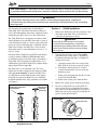
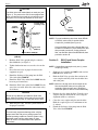
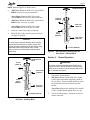
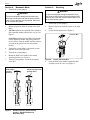
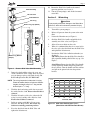
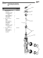
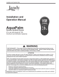
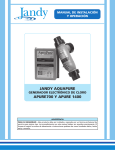
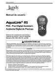
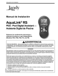
Installation and Operation Data
Installation and
Operation Manual
Jandy® Slide
Backwash Valve
H0569400B
FOR YOUR SAFETY - This product must be installed and serviced by authorized personnel
qualified in pool/spa installation and maintenance. Improper installation and/or operation
will void the warranty.
Page 3
FOR YOUR SAFETY: This product must be installed and serviced by authorized personnel qualified
in pool/spa installation and maintenance. Improper installation and/or operation will void the warranty.
WARNING
Ensure that all electrical power to the system is turned off before approaching, inspecting or
troubleshooting any leaking valves that may have caused other electrical devices in the surrounding
area to get wet.
This document gives instructions for installing the
Jandy Slide Valve. The instructions must be followed
exactly. Read through the instructions completely before
starting the procedure. Please save these instructions.
The Jandy Slide Valve is designed to be used on either
sand or diatomaceous earth (DE) filters with a center to
center dimension of eight (8") inches (center of the inlet
port to the center of the outlet port). Combined with the
Jandy Versa-Coupler, the Slide Valve can be used on
filters with center to center dimensions of seven (7") to
nine (9") inches.
For Jandy Filters, Slide Valve p/n SVLV8 (with unions)
is ready to mount to DEL48 or DEL60 model filters
(in which the top port is the filter outlet). If mounting a
Jandy Slide Valve on Pentair or Sta-Rite Filters, use a
combination of p/n SVLV2 (Slide Valve without unions)
and p/n 8044 (Versa-Coupler Kit).
The Slide Valve is a two position valve. The valve
handle must be fully extended or fully depressed. This
valve can not be throttled. To operate the Slide Valve
on a DE filter in normal filtration mode, fully depress
the handle. To operate the Slide Valve on a sand filter
in normal filtration mode, fully extend the valve handle
(see Figure 1).
DE Filter
Handle fully depressed
(pushed down)
Sand Filter
Handle fully
extended
(pulled up)
Section 1.
1.
SVLV8 Installation
Remove the Slide Valve from the packaging. Twist
the handle on the Slide Valve several times to
verify that the piston moves freely.
WARNING
Ensure that all electrical power to the system
is turned off before approaching, inspecting or
troubleshooting any leaking valves that may have
caused other electrical devices in the surrounding
area to get wet.
2.
Turn off all power to the system. For retrofit
installations only, follow steps "a" through "d".
For new installations skip steps "a" through "d"
and proceed to step 3.
a.
Open the pressure relief valve on top of the
filter. Wait for all air to evacuate the system.
b. If the filter is below pool level, close the
suction and return line valves to isolate the
filtration system.
c.
Remove the drain plug from the filter. Let the
water drain from the filter.
d. Remove the existing valve from the filter.
3.
Remove the o-rings (2 total) from the packaging.
4.
Place the o-rings on the face of the union tail
pieces, where the face of the Slide Valve union
will connect to the filter bulkheads (see Figure 2).
Make sure each O-ring is properly seated into the
groove of each union tail piece.
Coupling Nut
Union Tail Piece
O-ring
Figure 2. O-ring Placement
Figure 1.
Handle Positions - Filter/Circulation
Mode(SVLV2 shown)
Page 4
Alignment
Mark
CAUTION
The Slide Valve has molded labels on each port (see
Figure 1). The ports on the SVLV8 are equipped with
union connections that match the connections on the
filter ports. Do not use pipe sealants on union nuts.
To Filter Body
(cut away view)
To Pool
(PORT A)
Filter Outlet
(PORT C)
VersaCoupler
p/n 8044
Figure 4. Jandy Versa-Coupler
NOTE: For new installations other than Jandy DEL48
or DEL60, use the SVLV2 and the Versa
Coupler Kit, p/n 8044 (See Figure 4).
From
Pump
(PORT B)
If using the Slide Valve with a Pentair filter, use
Pentair Pool Products™ Union Set #27002, and
then proceed to section B. If using a Sta-rite
filter, use Sta-Rite® Union Set #PKGM188, then
proceed to section B.
Filter Inlet
(PORT D)
To Waste (PORT E)
Figure 3.
SVLV8 Installed on Jandy DEL48 or
(DEL60)
Section 2.
SVLV2 and Versa-Coupler
Installation
5.
Hold the Slide Valve upright and place onto the
filter bulkheads (see Figure 3).
6.
Tighten both union nuts to secure the valve on the
filter.
NOTE Certain filters may require only one (1) versacoupler (p/n 8044).
7.
Place filter and valve in proper location on the
equipment set pad.
1.
8.
Plumb the discharge of the pump into the Slide
Valve inlet labeled PORT B.
Slide one versa-coupler into PORT C and one into
PORT D on the Slide Valve.
2.
9.
Plumb the Slide Valve outlet labeled PORT A to the
heater or pool return lines.
Hold the Slide Valve up to the filter and twist the
versa-couplers until they slide into the filter inlet
and outlet ports.
10. Plumb the Slide Valve outlet labeled PORT E to the
waste line as needed. Allow the connections to dry
for 24 hours.
CAUTION
Do not let any adhesive get inside the Slide Valve
body. Adhesive inside the valve body will prevent the
piston from moving freely, or cause the valve to leak.
NOTE Make sure to align each versa-coupler to the
filter and the Slide Valve prior to gluing the
assembly. When the parts are in alignment,
mark each piece to ensure correct reassembly.
3.
Remove the valve from the filter. Clean the versacouplers and glue them onto the valve using the
alignment marks as a reference.
4.
Clean the versa-coupler and glue onto the filter.
Hold the coupler in place for a minimum of one
(1) minute.
5.
Plumb the discharge of the pump into the Slide
Valve inlet labeled PORT B.
11. When the glue is dry, start the system and check
for proper water flow.
CAUTION
To avoid costly equipment damage, after verifying
proper water flow and prior to putting system into
normal operating conditions, flush the system using
Backwash mode until the waste water is clean.
Refer to Section 4 for Backwash mode operation
instructions.
Page 5
NOTE Refer to Figure 5 for Steps 6 and 7.
6.
Handle Pulled Up
(DE Filters) Plumb the Slide Valve outlet labeled
PORT A to the heater or pool return lines.
(Sand Filters) Plumb the Slide Valve outlet
labeled PORT E to the heater or pool return lines.
7.
To Waste
(PORT A)
(DE Filters) Plumb the Slide Valve outlet labeled
PORT E to the waste line as needed.
Filter Inlet
(PORT C)
(Sand Filters) Plumb the Slide Valve outlet
labeled PORT A to the waste line as needed.
8.
Allow the connections to dry for 24 hours.
9.
When the glue is dry, start the system and check
for proper water flow.
From
Pump
(PORT B)
Filter Outlet
(PORT D)
CAUTION
To avoid costly equipment damage, after verifying
proper water flow and prior to putting system into
normal operating conditions, flush the system using
Backwash mode until the waste water is clean.
Refer to Section 4 for Backwash mode operation
instructions.
Handle Pushed
Down
To Pool
(PORT A)
Filter Outlet
(PORT C)
To Pool (PORT E)
Figure 6.
SVLV2 Plumbing Configuration for
Sand Filters - Filtration Mode
Section 3.
Normal Operation
WARNING
To prevent equipment damage and possible injury,
the pump must be turned off and the pressure relief
valve on top of the filter must be opened. Wait for all
air to evacuate the system
1.
Turn off the system pump(s).
2.
(DE Filters) Ensure that the Slide Valve handle
is fully depressed (handle and piston pushed all
the way down). Turn the handle until the stainless
steel pin on the piston locks into the position
bracket.
From
Pump
(PORT B)
Filter Inlet
(PORT D)
(Sand Filters) Ensure that the Slide Valve handle
is fully extended (handle pulled all the way up).
To Waste (PORT E)
Figure 5.
SVLV2 Plumbing Configuration for
DE Filters - Filtration Mode
3.
Turn on the filter pump(s). Check the system for
normal water flow.
Page 6
Section 4.
1.
Backwash Mode
Section 5.
Turn off the system pump(s).
WARNING
To prevent equipment damage and possible injury,
the pump must be turned off and the pressure relief
valve on top of the filter must be opened. Wait for all
air to evacuate the system
Servicing
WARNING
To prevent equipment damage and possible injury,
the pump must be turned off and the pressure relief
valve on top of the filter must be opened. Wait for all
air to evacuate the system
1.
Turn off the system pump(s).
2.
Release all pressure from the system at the main
filter.
2.
Release all pressure from the system at the main
filter.
3.
(DE Filters) Ensure that the Slide Valve handle is
fully extended (handle pulled all the way up). See
Figure 7.
3.
Loosen the lid union nut (see Figure 8).
Lid Union Nut
(Sand Filters) Ensure that the Slide Valve handle
is fully depressed (handle and piston pushed all
the way down). Turn the handle until the stainless
steel pin on the piston locks into the position
bracket.
4.
Turn on the system pump(s) and run the system
until the waste water runs clean.
5.
Turn off the system pump(s).
6.
Return the Slide Valve handle to the normal
operating position (see Section 3).
7.
Turn on system pump(s) and check for normal
water flow.
DE Filter
Handle fully
extended
(pulled up)
Figure 7.
Sand Filter
Handle fully depressed
(pushed down)
Handle Positions (SVLV2 shown)
Caution - Handle Positions for
Backwash Only
Figure 8.
4.
Loosen Lid Union Nut
Grab the Slide Valve handle and pull the shaft
assembly out of the valve (see Figure 9).
Page 7
Shaft Assembly
Lid Union Nut
Index Plate/Lid
10. Return the Slide Valve handle to the normal
operating position (see Section 3).
11. Turn on system pump(s) and check for normal
water flow.
Section 6.
Winterizing
Lid O-ring
Shaft O-ring, Top (Black)
CAUTION
If not properly winterized, damage to the Slide Valve
will occur, which will increase the potential of injury.
1.
Turn off the system pump(s).
2.
Release all pressure from the system at the main
filter.
3.
Loosen the lid union nut (see Figure 8).
4.
Grab the Slide Valve handle and pull the shaft
assembly out of the valve (see Figure 9).
5.
Allow all water to drain out the valve.
6.
When it is confirmed that there is no water left in
the valve, place the shaft back into the Slide Valve
and tighten the lid union nut.
7.
Position the Slide Valve in Backwash mode (see
Section 4).
(DE Filters) Ensure that the Slide Valve handle is
fully extended (handle pulled all the way up). See
Figure 7.
Shaft O-ring, Bottom
(Purple)
Figure 9.
Remove Slide Valve Shaft Assembly
Inspect the shaft and the o-rings for wear, cuts,
cracks, and debris. If the o-rings show any sign of
wear or damage, replace with Jandy O-ring and
Roll Pin Replacement Kit (P/N R0442100).
6.
7.
Wash the shaft and o-rings with clean water and
dry with a lint-free cloth. Ensure that all debris is
removed.
Wash the lid surface of the valve (where the lid
o-ring is seated) and dry with a lint-free cloth.
Ensure that all debris is removed.
8.
Lubricate o-rings with 100% silicone grease
lubricant, like Magic Lube®. Do not use any
lubricant containing petroleum products.
9.
Place the shaft back into the Slide Valve and
tighten the lid union nut.
11.5
5.0
9.2
4.0
6.9
3.0
4.6
2.0
2.3
1.0
0.0
0
25
50
75
100
Pressure Loss, PSI
NOTE The o-ring inspection includes the Lid o-ring.
Please be aware that the roll pins are different
lengths; the handle roll pin is 1" long and the
shaft roll pin is 13/16" long.
Feet of Hd, Ft. hd.
5.
(Sand Filters) Ensure that the Slide Valve handle
is fully depressed (handle and piston pushed all
the way down). Turn the handle until the stainless
steel pin on the piston locks into the position
bracket.
0.0
125
Flow Rate, GPM
Figure 10. Slide Valve Performance Curve (Slide Valve with DE Filter Data Shown)
Page 8
Section 6.
Jandy Slide Valve Exploded
View and Replacement Parts
List
Key
No.
Description
1
Rebuild Kit (O-rings, Roll Pins
and Index Plate/Lid)
O-ring, Lid
O-ring, Shaft, Top, Black
O-ring, Shaft, Bottom,
Purple
O-ring, Union Tail Piece
Roll Pin, Handle (1")
Roll Pin, Shaft (13/16")
Index Plate/Lid
2
3
Shaft Replacement Kit
Shaft
Handle
Roll Pin, Handle (1")
Roll Pin, Shaft (13/16")
Index Plate/Lid
Lid Union Nut
O-ring, Lid
O-ring, Shaft, Top, Black
O-ring, Shaft, Bottom,
Purple
Handle Replacement Kit
Handle
Roll Pin, Handle (1")
Roll Pin, Shaft (13/16")
Lid Union Nut
Lid O-ring
Qty.
2, 3
1, 2, 3
Order
Part No.
R0442100
2, 3
1
1
1
1, 2
2
1
1
1
R0442200
1
1
1
1
1
1
1
1
1
1, 2, 3
2
R0442300
1
1
1
1
1
1, 2
1, 2, 3
1
Page 9
NOTES
Page 10
NOTES
LIMITED WARRANTY
Thank you for purchasing Jandy® pool and spa products. Waterpik Technologies (manufacturer of Jandy
products, including Laars® pool and spa heaters, Air Energy Heat Pumps, and Clormatic Electronic Chlorine
Generators) warrants all parts to be free from manufacturing defects in materials and workmanship for a period of
one year from the date of retail purchase, with the following exceptions:
• AquaLink® RS units installed with Jandy Surge Protection Kits will be covered for two years.
• NeverLube® valves are warranted for the life of pool and/or spa on which they were originally installed.
• AquaPureTM Electronic Chlorine Generator Electrolytic Cells carry a 5 year limited warranty on a prorated basis.
This warranty is limited to the first retail purchaser, is not transferable, and does not apply to products that have
been moved from their original installation sites. The liability of Waterpik Technologies shall not exceed the repair
or replacement of defective parts and does not include any costs for labor to remove and reinstall the defective
part, transportation to or from the factory, and any other materials required to make the repair. This warranty does
not cover failures or malfunctions resulting from the following:
1. Failure to properly install, operate or maintain the product(s) in accordance with our published Installation,
Operation and Maintenance Manuals provided with the product(s).
2. The workmanship of any installer of the product(s).
3. Not maintaining a proper chemical balance in your pool and/or spa [pH level between 7.2 and 7.8, Total
Alkalinity (TA) between 80 to 120 ppm, Total Dissolved Solids (TDS) less than 2000 not including salt ppm].
4. Abuse, alteration, accident, fire, flood, lightning, rodents, insects, negligence or acts of God.
5. Scaling, freezing, or other conditions causing inadequate water circulation.
6. Operating the product(s) at water flow rates outside the published minimum and maximum specifications.
7. Use of non-factory authorized parts or accessories in conjunction with the product(s).
8. Chemical contamination of combustion air or improper use of sanitizing chemicals, such as introducing
sanitizing chemicals upstream of the heater and cleaner hose or through the skimmer.
9. Overheating; incorrect wire runs; improper electrical supply; collateral damage caused by failure of O-Rings,
DE grids, or cartridge elements; or damage caused by running the pump with insufficient quantities of water.
LIMITATION OF LIABILITY:
This is the only warranty given by Waterpik Technologies. No one is authorized to make any other warranties on
Waterpik Technologies' behalf. THIS WARRANTY IS IN LIEU OF ALL OTHER WARRANTIES, EXPRESSED
OR IMPLIED, INCLUDING BUT NOT LIMITED TO ANY IMPLIED WARRANTIES OF FITNESS FOR A
PARTICULAR PURPOSE AND MERCHANTABILITY. WATERPIK TECHNOLOGIES EXPRESSLY DISCLAIMS
AND EXCLUDES ANY LIABILITY FOR CONSEQUENTIAL, INCIDENTAL, INDIRECT OR PUNITIVE
DAMAGES FOR BREACH OF ANY EXPRESSED OR IMPLIED WARRANTY. This warranty gives you specific
legal rights. You may also have other rights which vary by state or province.
H0569400B
WARRANTY CLAIMS:
For prompt warranty consideration, contact your dealer and provide the following information: proof of purchase,
model number, serial number and date of installation. The installer will contact the factory for instructions
regarding the claim and to determine the location of the nearest designated service center. If the dealer is not
available, you can locate a service center in your area by visiting www.jandy.com or by calling our technical
support department at (707) 776-8200 extension 260. All returned parts must have a Returned Material
Authorization number to be evaluated under the terms of this warranty.
A Waterpik Technologies Company
6000 Condor Drive • Moorpark, CA USA 93021 • 707.776.8200 • Fax 707.763.7785
480 S. Service Road West • Oakville, Ontario, Canada L6K 2H4 • 905.844.8233 • Fax 905.844.2635
Litho in U.S.A. © Waterpik Technologies 0505