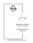
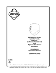
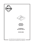
1
®
WIRETR
ON
AUX
1
AUX
3
PAN
AUTO
CAM
ON
2
4
MAN
OFF
UP
LEFT
RIGHT
ZOOM FOC
US IRIS
TELE NEA
R OPEN
DOWN
WIDE
FAR
CLOSE
ON
OFF
MPT8000 Series
Wiretron Digital
Transmitter/
Controller and
WX8000 Series
Receiver/Driver
Installation/
Operation Manual
C585M-B (11/98)
UL
®
LISTED
Pelco • 300 W. Pontiac Way, Clovis • CA 93612-5699 USA • Pelco Online @ http://www.pelco.com
In North America and Canada: Tel (800) 289-9100 or FAX (800) 289-9150 • DataFAX (800) 289-9108
International Customers: Tel (1-559) 292-1981 or FAX (1-559) 348-1120 • DataFAX (1-559) 292-0435
CONTENTS
Section
Page
1.0 GENERAL .................................................................................................. 5
1.1 IMPORTANT SAFEGUARDS AND WARNINGS ............................... 5
1.2 UNPACKING INSTRUCTIONS .......................................................... 6
1.3 RECOMMENDED TOOLS ................................................................. 6
2.0 DESCRIPTION .......................................................................................... 7
2.1 MODELS ............................................................................................ 7
2.1.1 Wiretron Digital Transmitter/Controller ................................... 7
2.1.2 Wiretron Receiver/Driver ....................................................... 8
2.2 CERTIFICATIONS ............................................................................. 8
3.0 INSTALLATION .......................................................................................... 9
3.1 RECEIVER 24 VAC POWER INPUT MODIFICATION ...................... 10
3.2 MOUNTING ...................................................................................... 12
3.2.1 Transmitter/Controller ........................................................... 12
3.2.2 Receiver ................................................................................ 12
3.3 WIRING ............................................................................................ 12
3.3.1 Control Wiring ....................................................................... 12
3.3.1.1 Wiring the Transmitter/Controller to the Receiver . 12
3.3.1.2 Wiring from the Receiver/Driver to the Pan/Tilt .... 13
3.3.2 Auxiliary Functions ................................................................ 16
3.3.3 Video Wiring ......................................................................... 16
3.3.3.1 Long Distance Cable Installation .......................... 18
3.4 POWER ............................................................................................ 19
4.0 OPERATION ............................................................................................. 21
4.1 AUTO/RANDOM OPERATION ......................................................... 21
5.0 MAINTENANCE ........................................................................................ 22
6.0 TROUBLESHOOTING .............................................................................. 22
6.1 RECEIVER PIN ASSIGNMENTS ..................................................... 23
7.0 SPECIFICATIONS .................................................................................... 24
8.0 WARRANTY AND RETURN INFORMATION ........................................... 28
2
Pelco Manual C585M-B (11/98)
LIST OF ILLUSTRATIONS
Figure
1
2
3
4
5
6
7
8
9
10
11
12
13
14
Page
Basic Wiretron System Configuration ................................................ 9
Multiple Camera Wiretron System ..................................................... 9
Circuit Board Electrical Connections ................................................ 10
24 VAC Power Input Modification Diagram ....................................... 11
Basic Wiretron Interconnect Diagram ............................................... 13
Connector Assembly ......................................................................... 14
Receiver Control Output/Input Pin Assignments ............................... 15
Jumper Settings on the Receiver Circuit Board ................................ 16
Auxiliary Functions Wiring Diagram .................................................. 17
External Device Wiring Diagram ....................................................... 17
Receiver Pin Assignments ................................................................ 23
MPT8000 Series Controller Dimension Drawing .............................. 25
WX8000 Series Receiver Dimension Drawing (Outdoor Models) ..... 27
WX8000 Series Receiver Dimension Drawing (Indoor Models) ....... 27
LIST OF TABLES
Table
A
B
C
Page
Control Cable Wiring Distances ........................................................ 12
Video Coaxial Cable Wiring Distances ............................................. 20
24 VAC Wiring Distances .................................................................. 20
REVISION HISTORY
Pelco Manual C585M-B (11/98)
Manual #
Date
Comments
C585M
1985
Original version.
C585M-A
4/90
Rev A. Revised manual to include instructions on
converting the WX802RX and WX8024RXI receiver/
drivers to operate on 24 VAC input voltage.
C585M-B
11/98
Rev B. Changed manual to new format. Completely
revised installation and operation instructions, and
added agency compliance certifications.
3
(This page intentionally left blank.)
4
Pelco Manual C585M-B (11/98)
1.0 GENERAL
1.1 IMPORTANT SAFEGUARDS AND WARNINGS
Prior to installation and use of this product, the following WARNINGS should be
observed.
1.
Installation and servicing should only be done by qualified service personnel
and conform to all local codes.
2.
Unless the unit is specifically marked as a NEMA Type 3, 3R, 3S, 4, 4X ,6 or
6P enclosure, it is designed for indoor use only and it must not be installed
where exposed to rain and moisture.
3.
Only use replacement parts recommended by Pelco.
4.
After replacement/repair of this unit’s electrical components, conduct a resistance measurement between line and exposed parts to verify the exposed
parts have not been connected to line circuitry.
The product and/or manual may bear the following marks:
This symbol indicates that dangerous voltage constituting a
risk of electric shock is present within this unit.
This symbol indicates that there are important operating and
maintenance instructions in the literature accompanying this
unit.
CAUTION:
RISK OF
ELECTRIC SHOCK.
DO NOT OPEN.
CAUTION:
TO REDUCE THE RISK OF ELECTRICAL SHOCK,
DO NOT REMOVE COVER. NO USERSERVICEABLE PARTS INSIDE. REFER SERVICING
TO QUALIFIED SERVICE PERSONNEL.
Please thoroughly familiarize yourself with the information
in this manual prior to installation and operation.
Pelco Manual C585M-B (11/98)
5
1.2 UNPACKING INSTRUCTIONS
Unpack and inspect all parts carefully.
The following items are supplied:
1
MPT8000 Series Wiretron Controller
or
1
1
WX8000 Series Receiver/Driver
Installation/Operation Manual (C585M-B)
Be sure to save the shipping carton, boxes and inserts. They are the safest materials in which to make future shipments.
If an item appears to have been damaged in shipment, replace it properly in its box
and contact the factory at 1-800-289-9100 or 1-559-292-1981 for a replacement.
(International customers fax 1-559-348-1120 for authorization and instructions.)
If an item needs to be returned to the factory for repair, consult the WARRANTY
AND RETURN INFORMATION section of this manual for instructions.
1.3 RECOMMENDED TOOLS
Pelco does not supply the basic tools needed for the installation process. The following tools are recommended.
Wire stripper
Wire cutter
AMP type crimper
Medium Phillips screwdriver
Power drill
6
Pelco Manual C585M-B (11/98)
2.0 DESCRIPTION
The Wiretron digital control system operates over a two-conductor cable and controls CCTV equipment such as pan/tilts, enclosures, and motorized zoom lenses
from a remote location up to 10 miles (16 km) away.
Wiretron can be configured to control a single site or interfaced with Pelco video
switching equipment to provide a convenient video/control system with multiple
control sites and/or multiple camera sites.
The Wiretron control system provides up to 15 remote control functions:
1.
2.
3.
4.
5.
6.
7.
8.
Pan Left
Pan Right
Tilt Up
Tilt Down
Zoom In
Zoom Out
Focus Near
Focus Far
9.
10.
11.
12.
13.
14.
15.
Iris Open
Iris Close
Auto/Manual Scan
Aux 1 (Manual Iris)
Aux 2 (Auto Iris)
Aux 3
Aux 4
Functions 1 through 10 are momentary; that is, they are actuated only while the
associated control switch is operated. Function 11 is latching; that is, auto scan
remains on until turned off. Aux 1, 2, 3, and 4 are low power outputs that may be
used to control such things as lights and gates. More auxiliary power output is
available when the controller is used with the AUX2000 Auxiliary Control Box. Aux
1-4 are jumper selectable for momentary/latching operation.
Functions 1 through 10 can be operated simultaneously. Functions 11 through 15
must be used individually, although any one of these functions may be used simultaneously with functions 1 through 10.
Wiretron provides the following standard functions on a single circuit board and
chassis with integral power supply:
1.
Pan/tilt (24 VAC or 120 VAC as ordered from the factory)
2.
Zoom lens–zoom, iris, focus with adjustable speed (speed not remotely controllable)
3.
Camera power (24 VAC or 120 VAC as ordered from the factory)
4.
An open collector transistor output (latching) for use in the manual override of
an automatic iris control
Wiretron is designed to combat erroneous control and execution by providing the
following protective functions:
1.
Simultaneous commands from two different sources are processed to ensure
that manual iris control cannot be inadvertently selected in place of automatic
control.
2.
A sustained (20-to-40 second) illegal command condition results in the following:
a.
Automatic iris
b.
Manual pan
2.1 MODELS
2.1.1 Wiretron Digital Transmitter/Controller
MPT8000CZ
MPT8000CZ/220
Pelco Manual C585M-B (11/98)
Desktop Wiretron transmitter/controller with pan/tilt joystick
and zoom lens control, 120 VAC input.
Same as MPT8000CZ except 230 VAC input
7
2.1.2 Wiretron Receiver/Driver
Outdoor
WX8024RX
WX8224RX
Wiretron receiver in weatherproof box for 24 VAC pan/tilts with
power supply for pan/ tilt, zoom lens, 24 VAC camera power,
120 VAC input
Same as WX8024RX except 230 VAC input
Wiretron receiver in weatherproof box for 120 VAC pan/tilts with
power supply for pan/ tilt, zoom lens, 120 VAC camera power,
120 VAC input
Same as WX8115RX except 230 VAC input, 230 VAC pan/tilt
output
Same as WX8024RX except 24 VAC input
Indoor
WX8024RXI
WX8024RXI/220
WX8224RXI
Same as WX8024RX except for indoor use, 120 VAC input
Same as WX8024RXI except 230 VAC input
Same as WX8024RXI except 24 VAC input
WX8024RX/220
WX8115RX
WX8220RX
2.2 CERTIFICATIONS
The products identified below have been tested and certified for agency compliance as noted.
Wiretron Digital Controller
Agency Compliance Certification
Model
MPT8000CZ
MPT8000CZ/220
CE
FCC
UL
X
CSA/cUL
Applicable CE, FCC, UL, and CSA/cUL standards:
•
UL Standard 2044
Additional applicable standards:
•
NEMA Type 1
•
IP 20
Wiretron Receiver/Driver
Agency Compliance Certification
Model
Outdoor
WX8024RX
WX8024RX/220
WX8115RX
WX8220RX
WX8224RX
Indoor
WX8024RXI
WX8024RXI/220
CE
FCC
UL
CSA/cUL
X
X
X
X
WX8224RXI
X
Applicable CE, FCC, UL, and CSA/cUL standards:
•
UL Standard 2044
Additional applicable standards:
•
NEMA Type 1 (RXI models)
•
NEMA Type 4 (WX8024RX/220; WX8024RXI/220; WX8220RX)
•
NEMA Type 4X (WX8024RX; WX8115RX; WX8224RX)
•
IP 20 (RXI models)
•
IP 56 (RX models)
8
Pelco Manual C585M-B (11/98)
3.0 INSTALLATION
The simplest Wiretron system, consisting of the control transmitter and receiver, is
shown in Figure 1. Up to 15 control functions are transmitted over the transmission
line to the remotely located receiver. These signals are then converted to drive
voltages or relay switching for auxiliary equipment being controlled. The basic system can be expanded to control multiple camera sites with the addition of a manual
video switcher with balanced audio follow (BAF), as shown in Figure 2.
WIRETRON
TRANSMITTER/
CONTROLLER
WIRETRON
RECEIVER
TWISTED PAIR
COAXIAL CABLE
MULTI-CONDUCTOR CABLE
Figure 1. Basic Wiretron System Configuration
WIRETRON
RECEIVER
MANUAL SWITCHER
WITH BAF OPTION
WIRETRON
TRANSMITTER/
CONTROLLER
WIRETRON
RECEIVER
TWISTED PAIR
COAXIAL CABLE
MULTI-CONDUCTOR CABLE
Figure 2. Multiple Camera Wiretron System
Pelco Manual C585M-B (11/98)
9
3.1 RECEIVER 24 VAC POWER INPUT MODIFICATION
The WX8024RX series receivers can be converted to operate with 24 VAC input.
To convert the receiver, disconnect the receiver circuit board and assembly from
the enclosure. The patch panel circuit board is located on the bottom of the receiver
circuit board mounting plate and requires the following modifications for 24 VAC
operation (refer to Figures 3 and 4.)
NOTE: Parts needed for modification: one 3 A fuse for F3.
1.
Turn off the power to the receiver and remove the power cord.
2.
Remove all wires from patch panel sections T2 and T3 with the exception of
the red wire connected to T3-1 and the red/white wire connected to T3-3.
3.
Remove jumper wires from J4 pins 8 and 9 and J5 pins 8 and 9.
4.
Remove transformer T2 (small transformer) and store for future use or discard.
WARNING: High voltage is present on the T3
transformer wires when
the unit is connected to
power. Be sure the wires
are insulated for safety.
5.
On transformer T3 (large transformer), insulate the wire ends on the black,
brown, black/white and brown/white wires.
6.
Locate the blue wire connecting fuse F3 to pin 7 of P7 (labeled F3) and disconnect at the P7 location. Reconnect to T3-3.
7.
Connect a jumper from J4 pin 9 to T3-1.
NOTE: When operating with 24
VAC input power, the distance from
the receiver to the 24 VAC power
supply is typically limited to any
conductor size/length combination
resulting in less than 5 ohms total
circuit resistance.
8.
Locate the wire connecting fuse F2 to pin 6 of P7 (labeled F2) and disconnect
at the P7 location. Reconnect to T2-3.
9.
Connect a jumper from J5 pin 9 to T2-1.
10. Change fuse F2 from 2/10 ASB to 1 AG.
11. Change fuse F3 from 1 ASB to 3 AG.
1
P6
66 94V0
9648
T3
T2
24V P/T
J2
3
5
110V
6
2
J2
3
J3
110V
J1 7
8
8
8
J4 J5 J6
9
9
9
GND J4 J5 J6 F1
6
2
J3
220V
4
4
1
5
110V
1
J1 7
J1
7
PCB1500526
REV. G
F2
F3
®
MADE IN U.S.A.
P7
AC HIGH
AC LOW
J2
110V
J3
110V
}
}
GND
6
3
220V
4
1
5
220V
110V
1
T1
28VCT
24V CAM
Figure 3. Circuit Board Electrical Connections
10
Pelco Manual C585M-B (11/98)
1
P6
66 94V0
9648
T3
T2
24V P/T
28VCT
24V CAM
J2
3
T1
110V
5
6
2
J2
3
J3
5
110V
6
220V
220V
4
1
110V
8
8
8
J4 J5 J6
9
9
9
GND J4 J5 J6 F1
F2
J3
220V
4
110V
110V
1
5
6
2
4
110V
J1 7
J2
3
J3
1
J1 7
J1
7
BLUE/WHITE
YELLOW
BLUE
F3
1
P7
T3
BROWN/WHITE
BROWN
BLACK/WHITE
CUT WIRES
SHORT AND
INSULATE
BLACK
RED
RED/WHITE
WHITE
GREEN
BLACK
BLUE
VIOLET
24 VAC INPUT
24 VAC OUTPUT
F2
CAM
1A
F3
P/T
3A
Figure 4. 24 VAC Power Input Modification Diagram
Pelco Manual C585M-B (11/98)
11
3.2 MOUNTING
3.2.1 Transmitter/Controller
NOTE: Never mount the receiver
with wiring connectors facing up.
Always have the connectors facing
down to prevent water damage.
Transmitter/controllers in the MPT8000 Series are desktop units. Determine the
best location for the unit.
Proceed to Section 3.2.2, RECEIVER.
3.2.2 Receiver
NOTE: When installing the
WX8000 receiver to a wall outdoors, seal the bolt holes with an
appropriate sealant. Apply the
sealant around the bolt holes between the unit and the mounting
surface. This will prevent possible
water damage to the wall caused
by rainwater leaking through the
mounting bolt holes. (This may only
be a problem when the mounting
bolts go completely though the
wall.)
1.
Determine the best location to install the unit.
2.
Using the WX8000 receiver box as a template, mark the hole pattern on the
mounting surface. Drill holes in the mounting surface.
3.
Attach the WX8000 receiver securely with four fasteners of appropriate length
(not supplied.)
Proceed to Section 3.3, WIRING.
3.3 WIRING
3.3.1 Control Wiring
3.3.1.1 Wiring the Transmitter/Controller to the
Receiver
Run the control cable between the controller/transmitter and the receiver (refer to
Figures 1 and 2.)
The control cable should be unshielded twisted pair wire. Maximum operating distances should be determined by referring to Table A, Control Cable Wiring Distances.
Table A. Control Cable Wiring Distances
Wire Gauge*
Maximum Distance
22 AWG
20 AWG
5 miles (8 km)
10 miles (16 km)
* Control cable operating distances are approximate according to wire used.
To wire the MPT8000 control wires, refer to Figure 5 and perform the following
instructions:
1.
Attach one wire from the terminal labeled HI on the MPT8000 Series controller to the terminal labeled HI on the WX8000 Series receiver.
2.
Attach one wire from the terminal labeled LOW on the MPT8000 Series controller to the terminal labeled LOW on the WX8000 Series receiver.
If you want to use a configuration that includes a switching device, refer to the
manual provided with the switcher for the appropriate connections.
Proceed to Section 3.3.1.2, WIRING FROM THE RECEIVER/DRIVER TO THE
PAN/TILT.
12
Pelco Manual C585M-B (11/98)
CAUTION:
HAZARDOUS
VOLTAGE
MAY EXIST
WX8000 SERIES RECEIVER
22
3
AC
LOW
2
GND
1
AC
HIGH
AC
INPUT
F3
1 P3
TEST
MODULE
CX900TLC
HI
LOW
AUTO/RANDOM
SCAN MODULE
A9000
GND
F2
F1
J2
PS 1
8
HI LOW GND
10
1 P2
P1 1
14
MPT8000 SERIES CONTROLLER
TB1
HI
LOW GND
AC INPUT
Figure 5. Basic Wiretron Interconnect Diagram
3.3.1.2 Wiring from the Receiver/Driver to the
Pan/Tilt
1.
Run multi-conductor cable between the receiver/driver and the pan/tilt (refer
to Figures 1 and 2.)
2.
Assemble the connector parts according to the following instructions. Detail B,
in Figure 6, reflects the pin arrangement specific to the WX8000 Series receiver/drivers. Refer to Figures 6 and 7 during assembly. For best results, use
an AMP style crimper when making the wire-to-pin connection.
The instructions that follow apply to all AMP style connectors regardless of pin size
or pin number.
Pelco Manual C585M-B (11/98)
1.
Slide the connector clamp assembly over the conductor cable. If the diameter
of the conductor cable is such that the rubber boot will slide over it easily then
slide the rubber boot onto the conductor cable at this time. If not, discard the
rubber boot.
2.
Prepare the wires from the conductor cable as follows:
a.
Strip at least 1-inch (2.54 cm) from the cable jacket to expose the wires.
You may need to strip more from the cable jacket if you have more wires.
b.
Strip 1/8-inch (0.318 cm) from each wire.
c.
Using an AMP style crimper, crimp the wires and their insulation to the
connector pins. Refer to Detail A in Figure 6.
13
3.
Slide the connector pins into the appropriate holes in the connector body until
they snap into place. Refer to Figures 4 and 5 for correct pin arrangement,
depending on model and options.
4.
Push the connector clamp assembly (with boot, if used) toward the connector
body. Screw the clamp assembly onto the connector body, being careful not to
disturb the wires.
5.
To complete the assembly, attach the appropriate clamp with the screws provided and tighten.
6.
When you are finished wiring the connector, connect the 37-pin assembly to
the WX8000 Series receiver/driver and the pan/tilt.
Proceed to Section 3.3.2, AUXILIARY FUNCTIONS.
1" (2.54 cm)
1/8"
(0.318 cm)
FRONT VIEW
OR
37-PIN
4
1
9
5
15
10
22
16
28
23
33
37
29
34
Figure 6. Connector Assembly
14
Pelco Manual C585M-B (11/98)
RECEIVER CONTROL
INPUT
PIN ASSIGNMENT
RECEIVER CONTROL
OUTPUT
PIN ASSIGNMENT
P1
3
BRN
P/T COM
1
5
ORG
LEFT
3
4
N/C
8
1
9
5
15
10
22
4
16
28
23
7
GRN
DOWN
5
6
BLU
UP
6
4
VIO
RIGHT
7
9
GRAY
GROUND
8
12
BLK
IRIS
10
1
11
W/BRN
FOCUS
11
3
10
W/RED
ZOOM
12
2
14
W/ORG
LENS COM
13
4
13
RED
MAN IRIS
2
5
1
WHITE
CAM AC HIGH
9
CAMERA
W/YEL
CAM AC LOW
14
POWER
10
BRN/W
N/C
28
9
RED/W
N/C
29
8
ORG/W
AUX 1
30
7
YEL/W
N/C
31
6
GRN/W
AUX 4
32
5
BLU/W
AUX 3
33
4
VIO/W
AUX 2
34
3
GRY/W
LOGIC RESET
35
2
W/GRY
GROUND
36
1
BLK/W
+10V
37
33
37
29
34
G
2
LENS
INPUT
P2
AUXILIARY WIRING
PROVIDED IN
OUTDOOR MODELS
ONLY.
NOTE: N/C MEANS NOT CONNECTED.
Figure 7. Receiver Control Output/Input Pin Assignments
Pelco Manual C585M-B (11/98)
15
3.3.2 Auxiliary Functions
WARNING: Mechanical
relays used must not exceed 10 VDC at 25 mA.
Applications with higher
power requirements
should be used with the
AUX2000 Auxiliary Control Box. Refer to the
AUX2000 manual for installation and operation
instructions.
The Wiretron receiver is capable of operating up to four remotely activated auxiliary
functions. Each auxiliary output may be individually converted at the receiver for
momentary or latching operation. Refer to Figure 8 to set jumpers for auxiliary functions. When in the latching mode, activating the same AUX function will toggle the
function from on to off.
The AUX outputs are buffered to provide a continuous 10 VDC at 25 mA to drive
small relays, lights or other external devices such as gates. Refer to Figures 9 and
10 for examples of typical circuits used for auxiliary functions.
Proceed to Section 3.3.3, VIDEO WIRING.
3.3.3 Video Wiring
Install a video cable from the video output of the camera to the video input of the
monitor (refer to Figures 1 and 2.) Proper termination of the video cable is vital to
the operation of the equipment. Be sure 75-ohm cable termination is made at the
monitor. Refer to Table B when wiring video coaxial cable distances up to 1,500 ft
(457 meters).
Proceed to Section 3.4, POWER, if finished wiring video.
Proceed to Section 3.3.3.1, LONG DISTANCE CABLE INSTALLATION, when
wiring longer distances.
JP1 AUX1
JP2 AUX2
JP3 AUX3
AUXILIARY JUMPER
SETTINGS ON THE
WIRETRON RECEIVER
BOARD. JUMPERS ARE
SHOWN IN THE MOMENTARY
“POSITION” OR “MODE”.
JP4 AUX4
LATCHING
MOMENTARY
P1
P2
37-PIN
CONNECTOR
CIRCUIT BOARD
POWER INPUT
WIRETRON RECEIVER
Figure 8. Jumper Settings on the Receiver Circuit Board
16
Pelco Manual C585M-B (11/98)
WIRETRON
Figure 9. Auxiliary Functions Wiring Diagram
+ 12 VDC
NORMALLY-OPEN
CONTACTS
WIRETRON
RECEIVER/DRIVER
37-PIN CONNECTOR
10 VDC RELAY
1N4005
CURRENT MAXIMUM
1
2
MANUAL IRIS
NOTE: CUSTOMER SUPPLIES PARTS AND 12 VDC
POWER SUPPLY
3
8
25 mA COIL
CONNECT TO NEGATIVE
SIDE OF 12 VDC SUPPLY
GROUND
Figure 10. External Device Wiring Diagram
Pelco Manual C585M-B (11/98)
17
3.3.3.1 Long Distance Cable Installation
Because of the many options available, long distance video wiring is at your discretion. Review the following to determine the best method of wiring video for your
application.
Maximum Distance Recommendations for Coaxial Cable
There are a number of variables to consider when specifying the type of coaxial
cable to run. It is best to avoid the use of video amplifiers. Video amplifiers should
be regarded as a remedy for an existing problem not as an installation aid.
Coaxial Splicing
Although not recommended, a splice in a coaxial cable is sometimes unavoidable
in long runs or difficult conduit pulls. A female-to-male BNC splice is the first choice
when splicing coaxial cable. An acceptable substitute is female-to-female with a
barrel adapter (although there is more signal loss inherent in this type of splice.)
The use of “F” connectors or barrels is not preferable because of the inferior mechanical connections and poor signal transmission characteristics inherent in those
connectors.
Direct Burial
Direct burial cabling should only be used when the cabling is specifically rated for
direct-burial use. Dig trenches and lay cable to a sufficient depth to accommodate
climate and other conditions and local codes. Protect cabling from damage that
may result from backfilling, traffic, burrowing animals, trenching, and other conditions.
Underground Conduit
Ensure that the cable is appropriate for use in underground conduit. Direct burial
cable is usually not acceptable for use inside a buried conduit that may fill with
water. Direct burial type of cable utilizes the earth surrounding the cable to wick
moisture away from the cable. Call your cable supplier or manufacturer for their
recommendations on the correct type of cable to use in circumstances where the
cable will be used in conduit.
One-inch PVC is the minimum recommended size for underground conduits. Allow
no more than two 90-degree bends between pull boxes. Make sure pull boxes and/
or splice boxes are as water-resistant as possible and that splices stay above any
water accumulation.
When using PVC, be sure to separate high voltage carrying conduits from video
conduits by enough distance to ensure that the video signal is not degraded. When
dealing with 120 VAC, about 12 inches of separation should be sufficient.
Aerial Spans
In some applications, it is preferable to run cable to a location overhead. If you want
to use existing poles consult with the owners, warrantors, or maintaining entities.
The poles may not be available for your use if the poles are owned by a public
service, utility, or cable TV provider.
If poles are in use by others, make sure that the addition of your cable and wire
complies with local codes and regulations. Proper spacing from existing wire and
cable, the descending order of voltage-carrying cable, and the minimum
low-clearance specifications over roads, alleys, and driveways etc. should be maintained.
Be aware of electrical inference that might be generated by high-voltage cables
sharing the poles with the video cabling. Legal spacing may not be enough to prevent electrical inference if radiated levels are high.
Hardware on poles should be appropriate to sustain the weight and stress of the
cable during adverse weather conditions.
Microwave
The WX8000 Series is excellent for microwave control. Consult with microwave
equipment manufacturers and/or suppliers for recommendations regarding operating specifications, and installation.
18
Pelco Manual C585M-B (11/98)
Fiber Optic Cabling
Fiber optic transmission of both video and control presents some distinct advantages. Higher quality and longer distance transmission characteristics, inherent noise
resistance, greater flexibility for usage, and reduced cabling diameter are but a few
of these advantages. The incorporation of fiber optics systems are encouraged,
especially when covering long distances and when seeking to maintain the highest
quality video signals. Consult with equipment manufacturers and fiber optic cabling
manufacturers or suppliers for recommendations regarding fiber optic type, operating specifications, and installation requirements.
Proceed to Section 3.4, POWER.
3.4 POWER
Pelco Manual C585M-B (11/98)
1.
Run wiring and connect receiver input power to AC HIGH, AC LOW, and ground.
If using 24 VAC to power the receiver, refer to Table C for the maximum recommended wiring distances.
2.
Power up the controller and receiver.
19
Table B. Video Coaxial Cable Wiring Distances
Cable Type*
Maximum Distance
RG59/U
RG6/U
RG11/U
750 ft (229 m)
1,000 ft (305 m)
1,500 ft (457 m)
* Minimum cable requirements:
75 ohms impedance
All-copper center conductor
All-copper braided shield with 95% braid coverage
Table C. 24 VAC Wiring Distances
The following are the recommended maximum distances for 24 VAC applications
and are calculated with a 10-percent voltage drop. (Ten percent is generally the
maximum allowable voltage drop for AC-powered devices.)
Wire Gauge
Total vA consumed
NOTE: Distances are calculated in
feet; values in parentheses are
meters.
20
18
16
14
12
10
10
283
(86)
451 716
(137) (218)
1142 1811 2880
(348) (551) (877)
20
141
(42)
225 358
(68) (109)
571 905 1440
(174) (275) (438)
30
94
(28)
150
(45)
238
(72)
380 603 960
(115) (183) (292)
40
70
(21)
112
(34)
179
(54)
285
(86)
452 720
(137) (219)
50
56
(17)
90
(27)
143
(43)
228
(69)
362 576
(110) (175)
60
47
(14)
75
(22)
119
(36)
190
(57)
301
(91)
480
(146)
70
40
(12)
64
(19)
102
(31)
163
(49)
258
(78)
411
(125)
80
35
(10)
56
(17)
89
(27)
142
(43)
226
(68)
360
(109)
90
31
(9)
50
(15)
79
(24)
126
(38)
201
(61)
320
(97)
100
28
(8)
45
(13)
71
(21)
114
(34)
181
(55)
288
(87)
110
25
(7)
41
(12)
65
(19)
103
(31)
164
(49)
261
(79)
120
23
(7)
37
(11)
59
(17)
95
(28)
150
(45)
240
(73)
130
21
(6)
34
(10)
55
(16)
87
(26)
139
(42)
221
(67)
140
20
(6)
32
(9)
51
(15)
81
(24)
129
(39)
205
(62)
150
18
(5)
30
(9)
47
(14)
76
(23)
120
(36)
192
(58)
160
17
(5)
28
(8)
44
(13)
71
(21)
113
(34)
180
(54)
170
16
(4)
26
(7)
42
(12)
67
(20)
106
(32)
169
(51)
180
15
(4)
25
(7)
39
(11)
63
(19)
100
(30)
160
(48)
190
14
(4)
23
(7)
37
(11)
60
(18)
95
(28)
151
(46)
200
14
(4)
22
(6)
35
(10)
57
(17)
90
(27)
144
(43)
Maximum distance from transformer to load
20
EXAMPLE: An enclosure that requires 80 vA and is installed 35 feet
(10 m) from the transformer would
require a minimum wire gauge of
20 AWG.
Pelco Manual C585M-B (11/98)
4.0 OPERATION
In general, all controller operating controls are self-explanatory. All controls, except
the ON/OFF power switch, are center-off, spring return switches (momentary onoff-momentary on.)
When using Aux 1-4 in the latching mode, operating the switch once will latch the
function and operating it again will unlatch the function.
The camera on/off switch is non-functional; the receiver is permanently in the ON
condition.
Reset causes latching functions to revert to the following:
1.
Manual scan
2.
Automatic iris
4.1 AUTO/RANDOM OPERATION
Auto scan and random scan modes are available when the A9000 Auto/Random
Scan plug-in module is installed in the Wiretron receiver. This module, when used
with the MPT8000 Series controller, allows control of pan and tilts. Refer to the
A9000 manual for installation and operation instructions.
Advantages of random scan:
Pelco Manual C585M-B (11/98)
1.
Because the scan direction, scan period, and dwell period are unpredictable,
unauthorized activities or intrusions are discouraged.
2.
Because of the reduced duty cycle, gear train wear, cable fatigue, drive motor
wear, and temperature rise are reduced. These factors contribute to system
reliability and increased equipment life.
21
5.0 MAINTENANCE
Regularly scheduled maintenance is not required. Clean the outer surface of the
controller or receiver with a non-abrasive cleaning cloth and antistatic cleaner. Do
not use kerosene or similar substances that may damage the surface.
6.0 TROUBLESHOOTING
If you experience operating problems with either the controller or receiver, first check
all fuses and voltage readings to make sure they are in working order.
Auxiliary Functions
Aux 1, 2, 3, and 4 are low power outputs that may be used to control such things as
lights and gates. More auxiliary power output is available when the controller is
used with the AUX2000 Auxiliary Control Box. Refer to the AUX2000 manual for
installation and operation instructions.
CX900TLC Manual Test Module
The CX900TLC Manual Test Module can be used to verify the receiver functions
and accessories are operational. The CX900TLC is a dual-purpose plug-in module
that permits local operation of all functions directly from the receiver unit, and serves
to verify that the receiver and accessories are operating properly by providing visual confirmation. This module also aids in troubleshooting receiver or controller
operational problems. Refer to the CX900TLC manual for installation and operation
instructions.
Also refer to Figure 11 for troubleshooting information.
For additional troubleshooting information contact your local dealer or Pelco.
22
Pelco Manual C585M-B (11/98)
6.1 Receiver Pin Assignments
Refer to Figure 11, Receiver Pin Assignments, when servicing the receiver.
INPUT POWER
PIN 12 14 VAC
PIN 11 GROUND(C)
PIN 10 14 VAC
PIN 9
PIN 8
PIN 7
PIN 6
PIN 5
PIN 4
PIN 3
PIN 2
PIN 1
GROUND
GROUND
N/C
N/C
PT LOW
PT HIGH
N/C
CAM LOW
CAM HIGH
MANUAL
CONTROL
FUNCTIONS
X
X
X
X
X
X
X
X
X
X
X
X
PIN 1
RIGHT
PIN 2
LEFT
PIN 3
UP
PIN 4
DOWN
PIN 5
ZOOM TELE
PIN 6
ZOOM WIDE
HARNESS TO PRESET BOARD P3
R21
1
+18 VDC
2
LENS SPEED
-18 VDC
3
GND
PIN 7
FOCUS FAR
4
PIN 8
FOCUS NEAR
PIN 9
IRIS OPEN
J3 (CX900TLC
TEST BOARD)
R55
DO NOT ADJUST!
PIN 12 AUX 2
WX8024/WX8224 MODELS
PINS 1,2,4, AND 5 ARE
24 VAC.
J1
K5
K4
(UP)
(DOWN) (CAM)
K1
K2
(LEFT)
K3
(RIGHT)
PIN 10 IRIS CLOSE
PIN 11 AUX 1
WX8115RX
PINS 1,2,4, AND 5 ARE
120 VAC.
PIN 13 AUTO IRIS
P1
PIN 14 AUX 3
HARNESS TO PTZ
OUTPUTS TO
37-PIN CONNECTOR
CAM HIGH
PIN 1
PIN 16 CAM OFF
CAM LOW
PIN 2
PIN 17 CAM ON
PT COMMON
PIN 3
PIN 18 MAN SCAN
RIGHT
PIN 4
PIN 19 AUTO SCAN
LEFT
PIN 5
PIN 20 ACTIVE LINE
UP
PIN 6
PIN 21 GROUND
DOWN
PIN 7
N/C
PIN 8
GROUND
PIN 9
ZOOM
PIN 10
FOCUS
PIN 11
IRIS
PIN 12
MAN IRIS
PIN 13
PIN 15 AUX 4
PIN 22 +10 VDC
JUMPER PIN 22 TO
PINS 1-19 OF J3 TO
ACTIVATE CONTROL
FUNCTIONS
R50
DO NOT ADJUST!
JP4
JP2
JP3
JP1
LATCHING
LENS COMMON PIN 14
MOMENTARY
P2
A9000 (AUTO/RANDOM SCAN BOARD) PLUG-IN STRIP J2
HARNESS TO AUX 2000
N/C
PIN 10
N/C
PIN 9
TTL AUX 1
PIN 8
N/C
PIN 7
TTL AUX 4
PIN 6
TTL AUX 3
PIN 5
TTL AUX 2
PIN 4
RESET
PIN 3
GROUND
PIN 2
+10 VDC
PIN 1
KEY TO SYMBOLS
SOCKET
PIN
ADJUSTABLE POT
X
K
RELAY
SOLDER LAND
Figure 11. Receiver Pin Assignments
Pelco Manual C585M-B (11/98)
23
7.0 SPECIFICATIONS
MPT8000 CONTROLLER
ELECTRICAL
Input Voltage
MPT8000CZ:
MPT8000CZ/220:
120 VAC, 60 Hz
230 VAC, 60 Hz
Power Consumption: 2.5 vA
Control Method:
15 pulse train (pulse width modulated)
Pulse Amplitude:
35 mA current loop
Connectors:
One 3-contact terminal block
Fuse Protection
MPT8000CZ,
MPT8000CZ/220:
One 1/16 A, 3AG, slow blow fuse
Power Cord:
3-wire grounded #18 AWG
Cable Requirements: Twisted pair, unshielded
Operating Distance:
Control cable distances are approximate according to wire
used.
Wire Gauge
Maximum Distance
22 AWG
5 miles (8 km)
20 AWG
10 miles (16 km)
CONTROLS
24
Power ON/OFF:
Rocker switch
Pan/Tilt:
8-position joystick
ZOOM:
Paddle switch, TELE/WIDE
FOCUS:
Paddle switch, NEAR/FAR
IRIS:
Paddle switch, OPEN/CLOSE
PAN AUTO/MAN:
Paddle switch (latching function in receiver)
CAMERA ON/OFF:
Paddle switch (non-functional; receiver permanently in ON
condition)
AUX 1, 2, 3, 4:
Paddle switch (receiver provides +10 V, 20 mA output which
can be used as latching or momentary functions)
Pilot Lamp:
Long life neon
Pelco Manual C585M-B (11/98)
GENERAL
Construction
and Finish:
Black polyester powder coated steel
Operating
Temperature:
32° to 120°F (0° to 49°C)
Dimensions:
See Figure 12
Weights
MPT8000CZ
MPT8000CZ/220
Unit
7.5 lb (3.36 kg)
7.5 lb (3.36 kg)
Shipping
8 lb (3.62 kg)
8 lb (3.62 kg)
WX8000 RECEIVER/DRIVER
ELECTRICAL
Input Voltage
WX8024RX,
WX8024RXI:
120 VAC, 50/60 Hz
WX8024RX220,
WX8024RXI/220:
230 VAC, 50/60 Hz
WX8115RX:
120 VAC, 50/60 Hz
WX8220RX:
230 VAC, 50/60 Hz
WX8224RX,
WX8224RXI:
24 VAC, 50/60 Hz
Power Consumption
Receiver:
5 vA (120 VAC or 24 VAC)
Pan/Tilt Supply:
140 vA max. (120 VAC) 50 vA max. (24 VAC)
Lens Supply:
0-4 vA max.
Camera Supply:
15 vA (typical)
Control Method:
15-pulse train (pulse width modulated)
Pulse Amplitude:
35 mA current loop
10.16 REF
(25.81)
14.32
(36.37)
AUX
1
AUX
3
PAN
AUTO
CAM
ON
UP
LEFT
2
4
MAN
OFF
ZOOM FOCUS IRIS
TELE NEAR OPEN
ON
WIDE
OFF
RIGHT
DOWN
FAR
CLOSE
FRONT VIEW
8.50
(21.59)
1.77
(4.50)
FRONT VIEW
TB1
HI LOW GND
AC INPUT
REAR VIEW
NOTE: VALUES IN PARENTHESES ARE CENTIMETERS; ALL OTHERS ARE INCHES.
Figure 12. MPT8000 Series Controller Dimension Drawing
Pelco Manual C585M-B (11/98)
25
Connectors
Receiver Input:
Receiver Output:
Fuse Protection
WX8024RX,
WX8024RXI
3-contact terminal block
37-pin AMP CPC for control output (mate supplied)
Fuse 1: Not used
Fuse 2: 2/10 A, 3AG, slow blow fuse
Fuse 3: 1 A, 3AG, slow blow fuse
WX8024RX/220,
WX8024RXI/220
Fuse 1: Not used
Fuse 2: 1/10 A, 3AG, slow blow fuse
Fuse 3: 1/2 A, 3AG, slow blow fuse
WX8115RX
Fuse 1: 2/10 A, 3AG, slow blow fuse
Fuse 2: 2/10 A, 3AG, slow blow fuse
Fuse 3: 1 A, 3AG, slow blow fuse
WX8220RX
Fuse 1: 1/10 A, 3AG, slow blow fuse
Fuse 2: 1/10 A, 3AG, slow blow fuse
Fuse 3: 1/2 A, 3AG, slow blow fuse
WX8224RX,
WX8224RXI
Fuse 1: Not used
Fuse 2: 1 A, 3AG, slow blow fuse
Fuse 3: 3 A, 3AG, slow blow fuse
Power Cord:
3-wire grounded, #18 AWG
Control Cable:
Twisted pair, unshielded
GENERAL
Construction and Finish
Outdoor Models:
Dark gray fiberglass
Indoor Models:
Alodine aluminum
Latching
Outdoor Models:
Two latches (accommodates padlocks - not supplied)
Operating
Temperature:
-4° to 140°F (-20° to 60°C)
Environment:
Indoor (RXI models)
Outdoor (All other models)
Weight
Unit
4 lb (1.81 kg)
Dimensions
Outdoor Models:
Indoor Models:
Shipping
6 lb (2.72 kg)
See Figure 13
See Figure 14
(Design and product specifications subject to change without notice.)
26
Pelco Manual C585M-B (11/98)
9.44
(23.98)
4.32
(10.97)
8.00
(20.32)
NOTE:
VALUES IN PARENTHESES ARE CENTIMETERS;
ALL OTHERS ARE INCHES
7.00
(17.78)
6.00
(15.24)
10.75
(27.31)
10.00
(25.40)
11.31
(28.73)
11.62
(29.51)
O .31 (.79) [4X]
Figure 13. WX8000 Series Receiver Dimension Drawing (Outdoor Models)
7.87 (19.99)
5.09 (12.93)
4.18
(10.62)
9.75
(24.76)
11.25
(28.58)
10.50
(26.67)
4.18
(10.62)
NOTE: VALUES IN PARENTHESES ARE CENTIMETERS; ALL OTHERS ARE INCHES
Figure 14. WX8000 Series Receiver Dimension Drawing (Indoor Models)
Pelco Manual C585M-B (11/98)
27
8.0 WARRANTY AND RETURN INFORMATION
WARRANTY
Pelco will repair or replace, without charge, any merchandise proved defective in
material or workmanship for a period of one year after the date of shipment. Exceptions to this warranty are as noted below:
•
•
•
•
•
•
Three years on Genex™ Series (multiplexers, server, and keyboard).
Two years on all standard motorized and fixed focal length lenses.
Two years on Legacy®, Intercept®, PV1000 Series, CM6700/CM8500/CM9500/
CM9750/CM9760 Matrix, Spectra®, DF5 Series and DF8 Fixed Dome products.
Two years on WW5700 series window wiper (excluding wiper blades).
Two years on cameras.
Six months on all pan and tilts, scanners or preset lenses used in continuous
motion applications (that is, preset scan, tour and auto scan modes).
Pelco will warranty all replacement parts and repairs for 90 days from the date of
Pelco shipment. All goods requiring warranty repair shall be sent freight prepaid to
Pelco, Clovis, California. Repairs made necessary by reason of misuse, alteration,
normal wear, or accident are not covered under this warranty.
Pelco assumes no risk and shall be subject to no liability for damages or loss resulting from the specific use or application made of the Products. Pelco’s liability for any
claim, whether based on breach of contract, negligence, infringement of any rights
of any party or product liability, relating to the Products shall not exceed the price
paid by the Dealer to Pelco for such Products. In no event will Pelco be liable for any
special, incidental or consequential damages (including loss of use, loss of profit
and claims of third parties) however caused, whether by the negligence of Pelco or
otherwise.
The above warranty provides the Dealer with specific legal rights. The Dealer may
also have additional rights, which are subject to variation from state to state.
If a warranty repair is required, the Dealer must contact Pelco at (800) 289-9100 or
(559) 292-1981 to obtain a Repair Authorization number (RA), and provide the
following information:
1.
2.
3.
Model and serial number
Date of shipment, P.O. number, Sales Order number, or Pelco invoice number
Details of the defect or problem
If there is a dispute regarding the warranty of a product which does not fall under
the warranty conditions stated above, please include a written explanation with the
product when returned.
Ship freight prepaid to:
Pelco
300 West Pontiac Way
Clovis, CA 93612-5699
Method of return shipment shall be the same or equal to the method by which the
item was received by Pelco.
RETURNS
In order to expedite parts returned to the factory for repair or credit, please call the
factory at (800) 289-9100 or (559) 292-1981 to obtain an authorization number (CA
number if returned for credit, and RA number if returned for repair). Goods returned
for repair or credit should be clearly identified with the assigned CA/RA number and
freight should be prepaid. All merchandise returned for credit may be subject to a
20% restocking and refurbishing charge.
® Pelco and the Pelco logo are
registered trademarks of Pelco.
© Copyright 1998, Pelco. All rights
reserved.
28
Ship freight prepaid to:
Pelco
300 West Pontiac Way
Clovis, CA 93612-5699
Pelco Manual C585M-B (11/98)