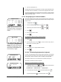
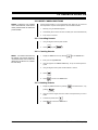
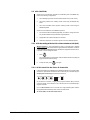
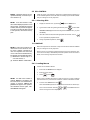
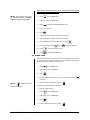
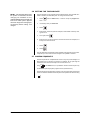
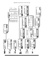
1
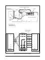
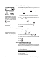
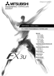
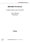
®
System
9750™
T
Bwd
Esc
9
8
7
4
Cam
In
Out
Mac
0
Near
Rcl
3
2
1
Fwd
Run
6
5
Alt
Far
se
Open Clo
ck
Prst Lo
Mon
CM9760-KBD/
CM9760-KBR
System 9760™
Keyboard
Installation/
Operation Manual
C540M (6/98)
Pelco • 300 W. Pontiac Way, Clovis • CA 93612-5699 USA • Pelco Online @ http://www.pelco.com
In North America and Canada: Tel (800) 289-9100 or FAX (800) 289-9150 • DataFAX (800) 289-9108
International Customers: Tel (1-559) 292-1981 or FAX (1-559) 348-1120 • DataFAX (1-559) 292-0435
CONTENTS
Section
Page
1.0 GENERAL ............................................................................................... 5
1.1 IMPORTANT SAFEGUARDS AND WARNINGS ............................... 5
1.2 CERTIFICATIONS ............................................................................. 5
2.0 DESCRIPTION .......................................................................................... 6
2.1 MAIN FEATURES .............................................................................. 6
2.2 MODELS ............................................................................................ 6
2.3 PHYSICAL LAYOUT .......................................................................... 7
2.3.1 LCD Display ........................................................................... 7
2.3.2 Multipurpose Function Keys .................................................. 7
2.3.3 Keypad ................................................................................... 7
2.3.4 User Definable Control Keys .................................................. 7
2.3.5 Function Control .................................................................... 8
2.3.6 Lens Control .......................................................................... 8
3.0 INSTALLATION AND SETUP ..................................................................... 9
3.1 INSTALLATION .................................................................................. 9
3.2 SETUP ............................................................................................... 9
3.2.1 To Activate Setup Mode ......................................................... 9
3.2.2 To Leave Setup Mode ...........................................................11
3.2.3 Creating a Setup PIN ............................................................ 11
3.2.4 Creating a Define PIN ...........................................................11
3.2.5 Calibrating the Joystick .........................................................11
3.2.6 Adjusting the Display Brightness .......................................... 11
3.2.7 Direct Camera Control/Serial Port Speeds ........................... 12
3.2.8 Configuring the Relays .........................................................13
3.2.9 User Definable Control Keys ................................................. 14
3.2.10 Setting Up a Receiver/Driver ................................................14
3.2.11 Downloading Keyboard Setups ............................................. 14
3.2.12 Assigning Logical Camera Numbers .................................... 15
3.2.12.1 Downloading Keyboard to Keyboard .....................15
3.2.12.2 Downloading Through the CM9760 System ......... 16
3.2.13 Adjusting the Time-out Period ............................................... 16
3.3 DIAGNOSTICS MODE ..................................................................... 17
3.3.1 Testing the display ................................................................ 17
3.3.2 Testing the keys ....................................................................17
3.3.3 Testing the serial ports .......................................................... 17
3.3.4 Testing the dip switch ............................................................ 17
4.0 OPERATION ............................................................................................. 18
4.1 INTRODUCTION .............................................................................. 18
4.2 OVERVIEW ....................................................................................... 18
4.3 LOGGING ON ................................................................................... 18
4.4 LOGGING OFF ................................................................................. 19
4.5 SELECTING MONITORS ................................................................. 19
4.6 SELECTING CAMERAS ................................................................... 19
4.7 LOCKING CAMERAS OR INPUT DEVICES .................................... 20
4.8 GROUP INPUT SELECTION ............................................................ 20
4.8.1 Selecting Group Cameras .................................................... 20
4.9 OPERATING PTZ CAMERAS ...........................................................21
4.10 OVERRIDING CAMERA CONTROL ................................................21
4.11 OVERRIDING CAMERA LOCKS ...................................................... 21
2
Pelco Manual C540M (6/98)
5.0 ADVANCED OPERATION ......................................................................... 22
5.1 PRESET CAMERA POSITIONS ...................................................... 22
5.1.1 Recalling Presets ..................................................................22
5.1.2 Creating Presets ................................................................... 22
5.1.3 Deleting Presets ................................................................... 22
5.2 VCR CONTROL ............................................................................ 23
5.2.1 VCR Recording with the Pelco Alarm Interface Unit (AIU) ..... 23
5.2.2 VCR Control Via the Pelco IR Controller ................................ 23
5.3 GPI CONTROL ................................................................................. 24
5.3.1 Selecting GPIs ....................................................................... 24
5.4 MACROS .......................................................................................... 24
5.4.1 Loading Macros ....................................................................24
5.4.2 Pausing Macros ....................................................................25
5.4.3 Restarting Macros ................................................................ 25
5.4.4 Finding Macros ..................................................................... 25
5.4.5 Deleting Macros ....................................................................26
5.4.6 Creating Temporary Macros ................................................. 26
5.5 VIDEO LOSS .................................................................................... 27
5.6 SETTING THE TIME AND DATE ...................................................... 28
5.7 CAMERA SEQUENCES ................................................................... 28
6.0 ALARMS
.............................................................................................. 29
6.1 ARMING ALARMS ............................................................................ 29
6.2 DISARMING ALARMS ...................................................................... 29
6.3 ALARM STATUS ............................................................................... 30
6.4 RESETTING ALARMS ..................................................................... 30
6.5 RESETTING TRIGGERED ALARMS ............................................... 30
7.0 APPENDICES ........................................................................................... 31
A
Keyboard LCD Default Menu and Tree Listing .................................. 31
B
Icon Legend ......................................................................................31
C
Keyboard Connector Pin-Outs .......................................................... 31
D
Keyboard to Keyboard Cabling Connections .................................... 31
E
Setup Mode Menu Tree (DIP Switch 2 ON) ...................................... 31
F
Diagnostic Mode Menu Tree (DIP Switch 1 ON) ............................... 31
G CM9760-KBD Specifications ............................................................ 31
8.0 WARRANTY AND RETURN INFORMATION ........................................... 40
Pelco Manual C540M (6/98)
3
LIST OF ILLUSTRATIONS
Figure
1
2
3
4
5
6
Page
The CM9760-KBD/9760-KBR ............................................................ 6
Default Menu Icons ............................................................................ 7
DIP Switches ..................................................................................... 9
Com Ports and DIP Switches............................................................. 9
Basic Keyboard Setup Configuration and Wiring ..............................10
Direct Mode Hookup ......................................................................... 12
REVISION HISTORY
Manual #
C540M
4
Date
Comments
6/97
Original version.
3/98
Included KBR and expanded direct control instructions.
Changed manual pagination. Added Section 1.2, Certifications.
6/98
Added Section 1.2, Certifications.
Pelco Manual C540M (6/98)
1.0 GENERAL
1.1 IMPORTANT SAFEGUARDS AND WARNINGS
Prior to installation and use of this product, the following WARNINGS should be
observed.
1.
Installation and servicing should only be done by qualified service personnel
and conform to all local codes.
2.
Unless the unit is specifically marked as a NEMA Type 3, 3R, 3S, 4, 4X, 6 or
6P enclosure, it is designed for Indoor use only and it must not be installed
where exposed to rain and moisture.
3.
Only use replacement parts recommended by Pelco.
4.
After replacement/repair of this unit’s electrical components, conduct a resistance measurement between line and exposed parts to verify the exposed
parts have not been connected to line circuitry.
The product and/or manual may bear the following marks:
Please thoroughly familiarize yourself with the
information in this manual
prior to installation and
operation.
This symbol indicates that dangerous voltage constituting a
risk of electric shock is present within this unit.
This symbol indicates that there are important operating and
maintenance instructions in the literature accompanying this
unit.
NOTE: This equipment has been
tested and found to comply with the
CAUTION:
limits of a Class A digital device,
RISK OF
pursuant to part 15 of the FCC
ELECTRIC SHOCK.
rules. These limits are designed to
DO NOT OPEN.
provide reasonable protection
against harmful interference when
the equipment is operated in a
CAUTION:
TO REDUCE THE RISK OF ELECTRICAL SHOCK,
commerical environment. This
DO NOT REMOVE COVER. NO USERequipment generates, uses, and
SERVICEABLE PARTS INSIDE. REFER SERVICING
can radiate radio frequency energy
TO QUALIFIED SERVICE PERSONNEL.
and, if not installed and used in
accordance with the instruction
manual, may cause harmful inter- 1.2 CERTIFICATIONS
ference to radio communications.
The products identified below have been tested and certified for agency compliOperation of this equipment in a
ance as noted.
residential area is likely to cause
harmful interference in which case
Agency Compliance Certification
the user will be required to correct
the interference at his own exModel
CE
FCC
UL
CSA/cUL
pense.
CM9760-KBD-X
X
X
CM9760-KBD
X
Applicable CE, FCC, UL, and CSA/cUL directives/standards:
Pelco Manual C540M (6/98)
•
93/68/EEC–CE Mark Directive
89/336/EEC, 92/31/EEC–Electromagnetic Compatibility (EMC) Directives
•
FCC–47 CFR, Part 15, Subpart B, Class A
5
2.0 DESCRIPTION
The CM9760-KBD/CM9760-KBR keyboard is the interface between the operator and
the CM9760 system. It can be used to select and maneuver cameras, and to control a
CM9760 system.
The keyboard is programmable, and can be used to create and execute macros.
This gives the operator access to effective monitoring procedures for any CCTV
application.
Many of the keys can be assigned both simple and complex functions. This allows
the keyboard to be configured by end-users to suit specific monitoring environments
(refer to Appendix G for specifications).
2.1 MAIN FEATURES
•
•
•
User-friendliness provided by specially designed icons
The ability to select and monitor any connected camera or video input
Control of maneuverable cameras for pan and tilt functions (where appropriate
equipment is fitted)
Control of the camera iris for zoom and focus (where appropriate equipment is fitted)
Control of camera auxiliary functions (where appropriate equipment is fitted)
Control of peripheral devices such as VCRs, video printers, frame stores and
video multiplexers
Selection of macros to execute complex procedures
The ability to arm and disarm alarms
The ability to store and recall camera motion presets (where appropriate equipment is fitted, such as pan and tilt heads, and motorized zoom lenses)
The ability to download user definable key configurations to and
from other keyboards
•
•
•
•
•
•
•
2.2 MODELS
System
CM9760-KBD
Programmable keyboard which serves as the interface between
the user/operator and the CM9760 system. 120 VAC, 60 Hz
CM9760-KBD-X
Same as CM9760-KBD except 230 VAC, 50 Hz
CM9760-KBR
Same as the CM9760-KBD, except it is the rack-mount version
of the keyboard.
CM9760-KBR-X
Same as CM9760-KBR except 230 VAC, 50 Hz
9750™
T
Bwd
ESC
3
2
1
5
4
MON
In
Out
Mac
0
Near
Rcl
9
8
7
Fwd
Run
6
Alt
Far
se
Open Clo
ck
Prst Lo
CAM
CM9760-KBD
CM9760-KBR
Figure 1. The CM9760-KBD/CM9760-KBR
6
Pelco Manual C540M (6/98)
2.3 PHYSICAL LAYOUT
The CM9760-KBD keyboard (see Figure 1) comprises:
1. Liquid crystal display (LCD)
4. User definable control keys
2. Multipurpose function keys
5. Function control
3. Keypad
6. Lens control
2.3.1 LCD Display
The LCD is a four-line display, in which:
Line 1
Line 1 displays the video output (which is typically a monitor),
and the video input source (which is often a camera). It also
indicates whether or not a selected input is defined as a PTZ
camera or VCR.
Line 2
Line 2 is used to display the status of the last data entry.
Line 3
Line 3 is used to display alarm messages, and other prompts.
Line 4
Line 4 is used to display icons. A complete icon list is illustrated
in Appendix B. The operational keyboard default Menu is
shown in Appendix A.
2.3.2 Multipurpose Function Keys
Icons indicate the functions to which each of eight multipurpose function keys
lead. Their changing purpose depends upon the mode of operation. Illustrated below are the icons of the default menu, the highest level menu of the CM9760-KBD.
The icons are selected using the multipurpose function keys.
2.3.3 Keypad
This section of the keyboard is a standard numeric keypad with added keys
to select cameras and monitors.
2.3.4 User Definable Control Keys
This section of the keyboard contains the user definable control keys, F1-F24. The
functions themselves can be varied according to the customer application and the
type of CCTV installation.
All 24 user definable control keys are programmable using the steps provided in
Section 3 of this guide.
Blank labels and a punched lexan decal overlay are provided as standard with the
CM9760-KBD.
DISPLAY
2
101
PTZ
ICONS
Figure 2. Default Menu Icons
Pelco Manual C540M (6/98)
7
2.3.5 Function Control
This section of the keyboard provides the following facilities:
Backward step through
available camera selections
Forward step through available
camera selections
Selection, creation and
execution of macros
Rcl: recall previous selections
Alt: cycle through inputs associated with election
Prst: recall preset
Lock: lock/unlock cameras to monitors
2.3.6 Lens Control
NOTE: The turbo button,
,
switches drives into high speed
mode, where they have this feature.
This section of the keyboard is used to control cameras equipped with motorized
zoom lenses and motorized pan-and-tilt units.
Using the CM9760-KBD keyboard, the operator can do the following:
•
Zoom in/out
•
Focus near and far
•
Open and close the iris
The joystick is proportional, enabling variable speed drives (where fitted) to be
speed controlled.
The proportional joystick provides operators with full control over the pan and tilt
movements, from minimum to maximum speed. The speed is proportional to the
amount by which the joystick is moved away from its rest (centered) location.
8
Pelco Manual C540M (6/98)
3.0 INSTALLATION AND SETUP
3.1 INSTALLATION
(Refer to Figure 5 on the next page)
1.
Ensure that all DIP switches are in the OFF position, as shown in Figure 3. The
DIP switches are on the underside of the keyboard.
2.
The RJ-45 connectors on the supplied Pelco power pack serve a dual function: (1) to provide power to the keyboard and (2), serve as a data path between the keyboard and the CM9760-CC1. Connect a “straight” or “parallel”
cable (RJ-45 to RJ-45) between COM 1 on the keyboard and the RJ-45 keyboard input connector on the power pack (refer to Figure 5).
3.
Connect the other “reverse” or “cross-wired” cable (also RJ-45 to RJ-45) between the remaining RJ-45 connector on the power pack and an appropriate
RJ-45 Sercom port (most likely Com port 6) of the Sercom board occupying
slot 1 on the rear of the Pelco CPU (CM9760-CC1).
4.
Plug the power pack into a 120 VAC power source.
5.
Turn the main power supply switch ON.
Figure 3. DIP Switches
VOLUME
RELAY
2
1C
COM 3
COM 2
COM 1
RESET
BUTTON
DIP SWITCHES
(REFER TO APPENDIX C FOR ALL KEYBOARD CONNECTOR PIN-OUTS)
Figure 4. Com Ports and DIP Switches
3.2 SETUP
NOTE: The DIP switches are on the
underside of the keyboard (see Figure 4). The default setup PIN is 1234.
It may be altered in setup mode. See
Appendix E, Setup Mode Menu Tree.
NOTE: To restore factory default
settings, set DIP switch positions 1,
2 and 8 to the ON position and recycle power.
The CM9760-KBD is configured using setup mode. In setup mode, it is possible to
•
Nominate a PIN for entering setup mode
•
Nominate a PIN that provides access to features on the define menu
•
Calibrate the joystick
•
Adjust the brightness of the display
•
Set the data transmission speeds at which the keyboard’s three COM ports operate
•
Configure the internal relays and assign macros to them
•
Assign functions to user-definable control keys
•
Select direct camera control receiver/drivers.
•
Assign logical camera numbers to directly controlled cameras.
•
Download/upload the definitions of the user-definable control keys and user
defined icons between keyboards
•
Adjust the time-out period
•
Select a host processor
3.2.1 To Activate Setup Mode
Pelco Manual C540M (6/98)
1.
Set DIP switch 2 to the ON position
2.
Enter your setup PIN.
9
* STRAIGHT OR PARALLEL CABLE
SERCOM BOARD
(LOCATED IN CM9760-CC1)
COM 1
PORTS
5 - 12
WALL-MOUNT POWER-PAC
PIN 1
PIN 1
(BOTTOM OF CM9760-KBD)
SERCOM
PORT 5
* REVERSE OR CROSS-WIRED CABLE
* SEE APPENDIX D FOR
INSTRUCTIONS ON
CABLE IDENTIFICATION
12 VDC KEYBOARD
INPUT POWER
POWER PAC
TX +
1
1
1
TX +
1
TX -
2
2
2
TX -
2
3
3
3
3
4
4
4
4
5
5
5
5
6
6
6
6
RX -
7
7
7
RX -
7
RX +
8
8
8
RX +
8
+ 12 VDC
GND
RJ-45
SERCOM PORT
RJ-45
COM 1
POWER
SUPPLY
CM9760-CC1
CM9760-KBD
120/230 VAC INPUT
Figure 5. Basic Keyboard Setup Configuration and Wiring
10
Pelco Manual C540M (6/98)
3.2.2 To Leave Setup Mode
1.
Select
and return DIP switch 2 to the OFF position.
3.2.3 Creating a Setup PIN
The factory settings for the CM9760-KBD include the default password 1234. An
alternative password can be defined as follows:
ADVANCE SETUP 4
> SETUP PIN
CONFIRM
DEFINE PIN
CONFIRM
****
****
****
****
NOTE: A PIN is required to enter
SETUP mode.
1.
While in setup mode, use
to locate Advance Setup 4.
2.
Select
3.
Select Confirm, retype the PIN, and select
and/or
, type a four-digit PIN, and select
once again.
once again.
3.2.4 Creating a Define PIN
NOTE: A PIN is required to use the
features that are accessible via the
DEFINE menu.
The factory settings for the CM9760-KBD include the default password, 1234. An
alternative password can be defined as follows:
1.
In setup mode, use
2.
Select Define PIN using
3.
Select
4.
Select Confirm, retype the PIN, and select
and/or
to locate Advance Setup 4.
and/or
.
, type a four-digit PIN, and select
once again.
once again.
3.2.5 Calibrating the Joystick
To make the joystick operational, proceed as follows:
JOYSTICK SETUP
XXX
XXX
(XXX, XXX)
XXX
XXX
1.
In setup mode, select
2.
With the joystick in the central default position, select
3.
Move the joystick fully left, and select
4.
Move the joystick fully right, and select
5.
Move the joystick fully down, and select
6.
Move the joystick fully up, and select
7.
Save the joystick configuration by selecting
8.
Select
.
.
.
.
.
.
.
.
3.2.6 Adjusting the Display Brightness
While in setup mode, the brightness of the display can be adjusted. This is done by
LCD BRIGHTNESS SETUP
selecting
NOTE: The display brightness can
also be adjusted by selecting
or
, after which the display may be brightened or darkened using
. When satisfied with the brightness setting, press
followed by
.
from
the define sub-menu. The define submenu is produced by selecting
Pelco Manual C540M (6/98)
.
11
3.2.7 Direct Camera Control/Serial Port Speeds
Intercept® receiver/drivers can be connected directly to the CM9760-KBD. In this
configuration, cameras are controlled directly by the keyboard, and not via an intermediate switching matrix controller. Thereafter they may be controlled directly.
CAMERA DIRECT CONTROL
> COM 1
COM 2
PELCO
PELCO
The receiver/drivers are connected to COM 1 and/or COM 2. Up to 16 cameras can
be connected to a single COM port, giving a maximum of 32.
Use Figure 6 as a guide for the physical connection of receiver/drivers and associated cameras to the CM9760-KBD for direct mode, then follow the below instructions for configuring the system in direct mode.
1.
2.
As before, enter direct setup by setting DIP switch 2 to the ON position, then
enter you setup PIN number; the main menu screen, “SETUP MODE”, will
appear.
Press the multipurpose key under the
icon and advance to the “Ad-
vance Setup 1” screen.
3.
Use
(
4.
and
,
to navigate to the “host” row and use the arrow keys
) to select “Direct Cam Ctrl.”
Use the
key to go to COM 1 and/or COM 2 and setup the keyboard
COM ports for the correct baud rate. Save, then Exit this screen to return to
the main menu “SETUP MODE” screen.
COM 2
COM 1
POWERPAK
PIN 1 TX+
PIN 2 TX-
PIN 1 TX+
PIN 2 TX-
PELCO CM9760-KBD
RECEIVER/
DRIVER
RECEIVER/
DRIVER
RECEIVER/
DRIVER
RECEIVER/
DRIVER
DIRECT MODE HOOKUP
(REMEMBER THAT TX+
GOES TO RX+ AND TXGOES TO RX- WHEN
CONNECTING YOUR
WIRES.)
RECEIVER/
DRIVER
UP TO SIXTEEN (16)
RECEIVER/DRIVERS
AND ASSOCIATED
CAMERA INPUTS
UP TO SIXTEEN (16)
RECEIVER/DRIVERS
AND ASSOCIATED
CAMERA INPUTS
RECEIVER/
DRIVER
Figure 6. Direct Mode Hookup
12
Pelco Manual C540M (6/98)
ADVANCE SETUP 1
> HOST SYSTEM 9750
COM 1
4800
8E
COM 2
4800
8E
COM 3
4800
8E
NOTE: Proceeding beyond COM 1
or COM 3 using
5.
Select the camera icon,
6.
The next screen gives you a choice for “Camera direct control type.” Change,
if necessary, the receiver/driver type listed as being attached to COM 1 and/or
COM 2 to the receiver/driver type you actually have connected to COM 1 and/
or COM 2 (usually this is Pelco).
7.
Continue with the
and/or
.
key to enter the “Camera Assign” menu screen and
configure the parameters as required for up to 32 physical cameras connected
causes the operator to arrive at a new
setup page. It is possible to return to
to COM port 1 (1-16) or COM port 2 (17-32). Use the
Advance Setup 1 by using
change or add Logical numbers and use the
or
and/
functional key to
function icon (if receiver is
capable) to assign toggle or momentary attributes for applicable AUX numbers 1-8. Use the ESC key to back out of the AUX menu.
.
8.
Save and return to the main “SETUP MODE” menu. Turn OFF DIP switch 2
first, then exit setup mode.
Serial Port Speeds
When it is necessary to adjust serial port speeds, do the following:
1.
In setup mode, select
to go to Advance Setup 1.
2.
Select the appropriate COM port using
3.
Choose the appropriate baud rate using
4.
Having adjusted the baud rate(s), select
and/or
.
and/or
.
and then
.
3.2.8 Configuring the Relays
ADVANCE SETUP 2
> RELAY 1 TOGGLE
MAC 1 0
RELAY 2 TOGGLE
MAC 2 0
NOTE: When a relay is in toggle
mode, a single key press will switch
it either ON or OFF. In momentary
mode, a relay will remain switched
ON only while the appropriate key is
held down.
Pelco Manual C540M (6/98)
Each CM9760-KBD keyboard has two relays which can be used in conjunction with
macros stored in the connected system, which will typically be the CM9760-CC1.
Macros are used to automate sequences of events. A simple macro might present
the operator with a view from one camera for five second, then switch to another
camera for 10 seconds, and so on. More complex macros can automate lengthy
and repetitive procedures, thus optimizing the collective CCTV system.
While in setup mode, it is possible to assign a macro to a relay, and also modify the
way in which the relay is switched. The relays can be switched in two ways: either
toggle or momentary.
To configure a relay:
from the setup mode menu.
1.
Select
2.
Use
3.
Select the relay using
4.
Define the relay action to be toggle or momentary using
5.
Select Mac (which is shown below the relay) using
.
6.
Select
once again.
7.
Repeat for second relay if desired.
8.
Having defined the relays, select
to advance beyond COM 3, and enter Advance Setup 2
and/or
.
, and enter the macro number. Select
followed by
or
.
.
13
3.2.9 User Definable Control Keys
The user definable control keys can be assigned various functions such as the
enter function. While in setup mode, functions can be assigned to the user definable control keys as follows:
KEYBOARD DEFINE MODE
> NOT DEFINED
NUM 0
KEY DEFINE
NUM 1
PLEASE ENTER A KEY
NUM 3
NUM 4
With the keyboard in setup mode, select
1.
mode. Select
NOTE: Many of the functions require
an additional attribute in the form of a
number, for which you will be prompted.
To enter such as a number: select
to switch to keyboard define
once again to define individual keys.
2.
Press the user definable control key to which a function is to be assigned. If
the pressed key is already defined, its assigned function will be shown.
3.
Using
and/or
, scroll the list of available functions. Align the de-
sired function with the arrow.
; type the number; then, select
once again.
NOTE: Section 3.2.11 shows how
to download and upload definitions of
the user definable control keys between keyboards.
4.
Select function by choosing
.
5.
To save user definable control key settings, select
6.
Having defined and saved the desired keys, select
7.
Select
.
.
.
NOTE: Several keys may be defined
prior to saving.
3.2.10 Setting Up a Receiver/Driver
NOTE: Do not intermix receiver/
drivers using a single port; usable
receiver/drivers comprise those using RS422 Pelco P-type protocol.
This would include most Legacy®,
Intercept® and System 9750/9760
ERD receiver/drivers.
1.
In setup mode, select
from the setup mode menu.
2.
Select COM 1 using
3.
Select the correct receiver/driver type using
4.
If necessary, repeat steps 2-3 to select the receiver/driver connected to COM 2.
5.
Select
6.
Select
and/or
.
and/or
.
.
.
3.2.11 Downloading Keyboard Setups
(See Appendix D for Keyboard Hook-up Details)
The CM9760-KBD keyboard setup can be downloaded and uploaded between keyboards. A keyboard setup can be uploaded to many other keyboards, avoiding the
need to configure each keyboard individually using setup mode. Keyboard setup
information can be downloaded/uploaded using one of two configurations:
1.
Keyboard to keyboard.
2.
Through the CM9760 system.
Setup information that can be downloaded/uploaded includes:
14
1.
User definable control keys.
2.
Relay configurations.
3.
Direct camera control parameters.
Pelco Manual C540M (6/98)
4.
Up to ten user-defined icons.
To upload a keyboard setup to all keyboards connected to a specific CM9760 system
in a multiple-node CCTV installation, you must know the appropriate node number.
To upload a keyboard setup to a specific keyboard connected to a specific CM9760
system in a multiple-node CCTV installation, you must know the keyboard number
(1-96) and the node number.
3.2.12 Assigning Logical Camera Numbers
CAMERA ASSIGN
PHYSICAL
>
0
1
2
3
LOGICAL
0
0
0
0
1
T
T
T
T
2
T
T
T
T
3
T
T
T
T
4
T
T
T
T
5
M
M
M
M
6
M
M
M
M
7
M
M
M
M
8
M
M
M
M
NOTE: Physical cameras 0-15 are
connected to COM 1, while physical
cameras 16-31 are connected to
COM 2.
LOGICAL
0
0
0
0
1
T
T
T
T
2
T
T
T
T
3
T
T
T
T
4
T
T
T
T
1.
In setup mode , select
2.
Select the camera assign screen using
3.
Select the physical camera number using
4.
Select
5.
Enter a logical camera number.
6.
Select
.
and/or
and/or
.
.
.
.
To configure the relays of directly controlled cameras:
AUX ASSIGN
PHYSICAL
0
>
1
2
3
Logical (user-defined) camera numbers can be assigned to directly controlled cameras. This avoids the need to change physical camera numbers. To assign a logical
camera number:
5
M
M
M
M
6
M
M
M
M
7
M
T
M
M
8
M
M
M
M
.
7.
Select
8.
Use the auxiliary icons, such as
, to set the camera’s relay action to
either toggle or momentary status.
NOTE: Each camera receiver/driver
may have up to eight relays, the action of which can be specified as either momentary or toggle.
9.
Press
.
10. Repeat steps 3-9 to configure additional cameras.
11. Select
.
3.2.12.1 Downloading Keyboard to Keyboard
KEYBOARD SETUP
> TARGET
NODE
KBD#
9750/9760
LOCAL
ALL/ANY
In order to download/upload setups directly between keyboards, the keyboards
can be connected using COM 1 and/or COM 2 (the ports are interchangeable in
this case, that is, COM 1 or COM 2 to COM 1 or COM 2) or through COM 3.
The COM port sockets are on the underside of the keyboard (see Figure 4).
The data pin connections are shown in Figure 5.
KEYBOARD SETUP
> TARGET
NODE
KBD#
Setups are downloaded keyboard to keyboard by:
KB - KB COM 1
1.
In keyboard setup mode, use
and/or
to select the COM port that
is being used to download setup information:
a) KB-KB COM 1
2.
b) KB-KB COM 2
c) KB-KB COM 3
To download setup information from a connected keyboard select
or,
to upload setup information to a connected keyboard, select
Pelco Manual C540M (6/98)
.
15
The Keyboard LCD will indicate that it is cycling through the camera map
settings; when finished, the LCD will display “End of Tx.”
3.2.12.2 Downloading Through the CM9760 System
NOTE: Enter 0 to select all nodes,
and enter 9999 to select the local
node only.
Setups can be downloaded/uploaded using keyboards connected to 9760 systems.
In this configuration, it is possible to upload the setup of a single keyboard to many
other selected keyboards simultaneously. It is even possible to upload the setup of
a single keyboard to all keyboards in a CCTV installation concurrently.
A CCTV installation may include multiple 9760 systems, each of which is referred
to as a node. The nodes are designated numbers from 1 to 9998. To download/
upload keyboard setups through the 9760 system:
1.
In keyboard setup mode, selectCM9760 using
2.
Using
, select Node.
3.
Select
.
4.
If necessary enter a node number in the range 1 to 9998.
5.
Select
once again.
6.
Using
select kbd# .
7.
Select
.
8.
Enter a keyboard number in the range 1 to 96, or enter 0 to select all
keyboards attached to selected node(s).
9.
Select
and/or
.
.
10. To download setup information from a connected keyboard, select
or,
to upload setup information to a connected keyboard, select
.
3.2.13 Adjusting the Time-out Period
ADVANCE SETUP 3
> AUTO LOGOFF (MIN) OFF
AUTO CAM REL (MIN) 1
2015 ALM R (SEC) OFF
NOTE: The automatic log-off function can be disabled by entering 0, 1,
or 255.
The period of keyboard inactivity which invokes the automatic log-off function can
be modified. Operators may be timed out after periods of inactivity ranging from 1
to 254 minutes. To specify a time-out period:
from the setup mode menu.
1.
Select
2.
Go to Advance Setup 3 using
3.
To enter a time-out period, select
and/or
.
, and type a duration between 2 and
254 (minutes).
16
4.
Select
once again.
5.
Select
.
6.
Select
.
Pelco Manual C540M (6/98)
3.3 DIAGNOSTICS MODE
Diagnostics mode is activated when DIP switch 1 is ON. To leave diagnostics mode,
ADVANCE SETUP 1
select
> HOST SYSTEM 9750
COM 1
4800
8E
COM 2
4800
8E
COM 3
4800
8E
and return DIP switch 1 to the OFF position. Diagnostics mode allows
you to test the:
1.
LCD display
2.
Keys
3.
Serial ports (not available at this time)
4.
DIP switches
3.3.1 Testing the Display
DIAGNOSTIC MODE V3.3
LCD TEST
1.
While in diagnostics mode, select
2.
Select
to test Graphic Page 0.
3.
Select
to test Graphic Page 1.
4.
Select
to test Graphic Page 2.
5.
Select
to test the text page.
6.
Select
.
.
3.3.2 Testing the Keys
KEYBOARD TEST V3.3
PLEASE ENTER A KEY
JOYSTICK POSITION - (129,129)
NOTE: When testing the keyboard,
pressing the user definable control
keys causes their assigned functions
to be displayed.
1.
While in diagnostics mode, select
.
2.
Press each key and check that the display indicates the correct key.
3.
Select
.
3.3.3 Testing the Serial Ports
(For factory use only)
3.3.4 Testing the DIP Switch
DIP SWITCH TEST V3.3
1.
Select
.
2.
Beginning with switch 2, set each switch to ON while observing the display.
00000011
NOTE: When switched ON, functioning switches will change the correspondingly displayed ‘0’ to a ‘1’. For
instance, when switch 2 is ON, the
display should read: 00000011.
Pelco Manual C540M (6/98)
17
4.0 OPERATION
4.1 INTRODUCTION
This chapter describes the operation of a CM9760 System using the CM9760-KBD.
The following is assumed:
1.
The CM9760 system is functional.
2.
Initial power-up has been completed.
3.
CM9760 setup files have been programmed.
You should also have the following information:
1.
A PIN that permits logging on
2.
If necessary, a PIN that provides access to the setup functions
3.
If necessary, a PIN that provides access to the define menu
4.
The logical camera number list, complete with identification names
5.
The logical monitor number list, complete with identification names
6.
A list of all macros
7.
A list of all peripheral devices connected (VCRs, video printers, GPIs)
8.
A list of alarms connected to the system
9.
A list of presets for each relevant camera
4.2 OVERVIEW
The CM9760 keyboard differs from conventional keyboards in that icons are used
to select required functions.
The icons simplify operation by indicating the exact functions which the associated
multipurpose function keys will implement.
Appendix B illustrates the Pelco 9760 icons, while Appendix A shows the menu
hierarchy.
4.3 LOGGING ON
To operate the keyboard, you must enter your four-digit PIN.
Upon entry of a valid PIN the keyboard will ask you to select the monitor you wish
to view. To select a monitor:
18
1.
Using the numeric keypad, enter the required monitor number.
2.
Press
.
Pelco Manual C540M (6/98)
4.4 LOGGING OFF
from the default menu, which can be reached by pressing
To log off, select
. This will result in the prompt Are you sure you want to log off? Select
to log off, or select
to remain logged on.
Alternatively, select monitor 0 to log OFF from any menu level without the log-off
prompt.
4.5 SELECTING MONITORS
1.
Using the keypad, enter a monitor number, and then press
or,
select
2.
from the default menu.
Cycle through the available monitor sequence using
and
.
If a user definable control key has been assigned the enter function, monitors
can be selected as follows:
1.
Press
.
2.
Enter a monitor number.
3.
Press the user definable control key that has been assigned the enter function - this can be located by referring to the decal.
4.6 SELECTING CAMERAS
1.
If necessary, select
from the default menu, to reach the camera sub-
menu.
2.
Cycle through available cameras using
and
or,
using the numeric keypad, enter a camera number and press
.
If a user definable control key has been assigned the enter function, cameras
can be selected as follows:
1.
Press
2.
Enter a camera number.
3.
Press the user definable control key that has been assigned the enter function - this can be located by referring to the decal.
and
Pelco Manual C540M (6/98)
.
can also be used to cycle through cameras.
19
4.7 LOCKING CAMERAS OR INPUT DEVICES
To lock a camera to a monitor (or other output device), select the appropriate camera or input, then select
.
4.8 GROUP INPUT SELECTION
The CM9760-KBD includes 24 user definable control keys. The user definable
control keys can be used for group input selections such as:
1.
2.
3.
4.
Car Park 1
Car Park 2
Mezzanine 1
Mezzanine 2
5.
6.
7.
Foyer 1
Foyer 2
VCR Bank 1
Upon selection of any of the above group input selections (to a single monitor),
the keyboard will default to the lowest logical input number within the selected
group.
In a casino application, the user definable control keys might be assigned the
following group selections:
1.
2.
3.
Black jack
Roulette
Craps
4.
5.
6.
Keno
Count room
Baccarat
User definable control keys might also be used to interface the operator(s) (either in groups or individually) with the following:
1.
VCR - to provide remote control of VCR functions
2.
Multiplexer - to provide remote control of multichannel displays
3.
Frame stores - to provide remote control of freeze and loop functions
Upon selection of a VCR, the multipurpose function keys are assigned appropriate control functions. The functions are indicated by the icons on line 4 of the display.
The user definable control keys can be allocated specific area selections.
Subsection 4.8.1 demonstrates this through an example.
4.8.1 Selecting Group Cameras
NOTE:
invokes the default
menu, or the top-level menu.
20
1.
Using the numeric keypad, enter group number.
2.
Press the appropriate user definable control key (for example, car park).
3.
To toggle to other associated cameras (or other types of inputs), use
4.
Control of associated functions is now possible using the multipurpose function keys .
.
Pelco Manual C540M (6/98)
4.9 OPERATING PTZ CAMERAS
The controls for PTZ cameras are located on the right-hand side of the keyboard
(see Figure 1). If a selected camera is a PTZ type, the operator will be informed via
a display prompt.
The joystick is proportional, enabling variable speed drives (where fitted) to be
speed controlled.
NOTE: It is possible to operate the
joystick simultaneously with a lens
function. The iris open and close
button only functions with the appropriate lens fitted.
The proportional joysticks give operators full control over the pan and tilt movements, from the minimum to the maximum speed. Speed is proportional to the
amount by which the joystick is moved away from its rest (centered) location.
enables immediate high speed operation.
Where a fixed speed pan/tilt drive unit is installed, the joystick will provide only
directional control.
The various functions of a PTZ camera may be controlled as follows:
1.
To zoom in or out, use
2.
To focus near or far, use
3.
To open or close the iris, use
.
.
.
4.10 OVERRIDING CAMERA CONTROL
NOTE: “Busy operator” will
appear if another operator has
greater access rights.
1.
With the camera sub-menu on screen, press and hold
2.
Move the joystick, or press a key on the camera control section of the keyboard.
.
4.11 OVERRIDING CAMERA LOCKS
NOTE: “Override Denied” will appear if another operator has greater
access rights.
Pelco Manual C540M (6/98)
1.
With the camera sub-menu on screen, press and hold
2.
Press
.
.
21
5.0 ADVANCED OPERATION
5.1 PRESET CAMERA POSITIONS
NOTE: Presets are only possible
when receiver/drivers, zoom lenses
and/or pan/tilt heads are fitted with
preset facilities.
A preset camera position is a set of parameters which define pan, tilt, zoom and
focus adjustments. A preset camera position can be recalled as follows:
1.
Manually, using the CM9760 keyboard
2.
Automatically as the result of an alarm condition (refer to the 9760 alarm file)
3.
From a macro command
5.1.1 Recalling Presets
1.
Using the keypad, enter the preset number.
2.
Select
or press
.
5.1.2 Creating Presets
NOTE: Your define PIN need only
be entered once during operation.
The default PIN is 1234. To alter the
define PIN, see Section 3.0, Installation and Setup.
1.
Display the define sub-menu by selecting
from the default menu.
2.
Enter your four-digit define PIN.
3.
Using the joystick and camera control keys, set up the camera preset required.
4.
Using the keypad, enter a preset number between 1 and 99.
5.
Select
.
6.
Select
to revert to the default menu.
5.1.3 Deleting Presets
1.
Display the preset sub-menu by selecting
pressing
22
on the default menu, or by
.
2.
Using the numeric keypad, enter the number of the preset that you wish to
delete.
3.
To delete the preset, select
4.
Select
.
to revert to the default menu.
Pelco Manual C540M (6/98)
5.2 VCR CONTROL
VCRs can be connected and controlled via a CM9760 system and CM9760 keyboard in the following configurations:
1.
Via a start/stop signal from the Pelco Alarm Interface Unit (no full control)
2.
Via a Relay Interface unit, enabling remote control using the CM9760 keyboard
3.
Via a Pelco Infra-Red Control System, enabling remote control using the
CM9760 keyboard
VCRs can be controlled from the CM9760 keyboard if
1.
The VCRs have been modified appropriately. For instance, it might be necessary to add hardware that provides alarm signal feedback.
2.
Appropriate Pelco interface equipment is included.
3.
VCR video outputs are connected as inputs to the Pelco CM9760 System.
5.2.1 VCR Recording with the Pelco Alarm Interface Unit (AIU)
Manual operation: in this configuration the VCR is connected from a CM9760
output in series to a video monitor. With an appropriate Pelco installation, and where
a user-definable control key has been allocated the appropriate VCR function, it
is possible to record footage as follows:
1.
Press
.
The corresponding key will illuminate, while the Alarm Interface Unit (AIU) will
trigger the VCR to start recording.
2.
To stop the VCR, press
once again.
5.2.2 VCR Control Via the Pelco IR Controller
In Pelco IR-based CCTV installations, the CM9760 keyboard can be used to select
VCRs and to operate their standard functions. VCRs may be controlled using the
multipurpose function keys that select the VCR icons:
,
,
,
,
, and
.
Via the Pelco IR controller, a single general purpose interface (GPI) is used to
control four VCRs, and a maximum of up to 32 GPIs can be accommodated by a
single IR controller.
Up to 16 IR Controllers can be connected to a single CM9760 system. Sixteen
fully populated IR Controllers provide control over 2048 VCRs.
To control VCRs, see Section 5.3 GPI control.
Pelco Manual C540M (6/98)
23
5.3 GPI CONTROL
NOTE: Peripheral devices can be
operated manually, or via macros (refer to Section 5.4).
A GPI can control up to eight relays. Relays are controlled from the auxiliary keys
on the CM9760 keyboard. A list of all GPIs and auxiliary keys should be available
from your manager or security supervisor.
5.3.1 Selecting GPIs
NOTE: If the GPI number is valid,
GPI n will be displayed (where n is the
GPI number). If the GPI has not been
installed, GPI not present will appear.
If access to the GPI has been denied
to that operator, GPI denied will appear.
1.
Display the GPI sub-menu, by selecting
from the default menu.
2.
Type the GPI number using the keypad and then press
,(or other user
definable control key that has been assigned the Enter function), or press
the GPI key.
3.
If the GPI number is valid, select the appropriate Aux channel, such as
,
so as to operate the peripheral device.
4.
Having completed all operations, select
.
5.4 MACROS
NOTE: A macro will not execute if it
calls for the use of a camera or monitor which is already controlled by a
user via a keyboard. The macro will
not run until control is released to it by
the operator. To accomplish this, either:
(1) Backward or forward step to a
non-PTZ camera, or
(2) Press the "MON" or "CAM" button.
Macros are sequences of commands or steps. A list of macros should be available
from your manager or security supervisor.
When a macro is run, the steps programmed into that macro are performed. Macros can be run manually or automatically. Automatic operation can be as a result of
alarms, or the reaching of specific times or dates.
5.4.1 Loading Macros
A macro can be loaded as follows:
NOTE: If a valid macro number is
entered, “Macro n” will appear, and
the macro will run. If an invalid macro
number is entered, “Macro not
present” will appear. If the operator
has insufficient access rights, “Access denied” will appear.
1.
Ensure that the default menu is displayed.
2.
Enter the macro number.
3.
Select
or press
.
When a macro completes all its steps, it stops and will only run again if restarted
(refer to Section 5.4.3). If the macro is continuous, it will run until cleared or halted.
4.
To return to the default menu, select
.
When the CM9760 keyboard is in normal mode, the selection of cameras by a
macro can be overridden. Selecting
and
on the macro sub-menu
causes running macros to be displayed.
24
Pelco Manual C540M (6/98)
5.4.2 Pausing Macros
To pause a macro:
1.
Select
to display the running macro number.
2.
Select
and
3.
When the required macro is selected, ensure that it is running by referring to
the display.
4.
If the macro is running, halt it by selecting
5.
Select
to step through macros that have been loaded.
.
to revert to the default menu.
5.4.3 Restarting Macros
1.
Select
to display the macros.
2.
Using
and
3.
If
4.
Select
, step through the loaded macros.
is highlighted, the macro is halted. Select
to restart the macro.
to revert to the default menu.
5.4.4 Finding Macros
To find a loaded macro:
Pelco Manual C540M (6/98)
1.
Select
from the default menu.
2.
Using
and
3.
Having located a loaded macro, select
, step through loaded macros to find that required.
to revert to the default menu.
25
5.4.5 Deleting Macros
To delete a macro:
1.
Using the numeric keypad, enter the required macro number.
2.
Press
to display the macro sub-menu.
3.
Select
to delete the specified macro.
or,
from the default menu.
1.
Select
2.
Step through the loaded macros using
3.
With the appropriate macro selected, choose
4.
Press
and
.
in order to delete it.
to return to the default menu.
5.4.6 Creating Temporary Macros
When programming a macro, it is possible to do the following:
26
•
Single step through a macro with
and
•
Delete a current macro step using
.
•
Insert a macro step before the current step using
•
Add a macro step to the end of a macro using
.
.
.
Pelco Manual C540M (6/98)
Using macros, camera sequences can be programmed directly from the
CM9760 keyboard. To program a macro:
NOTE: If the entered macro number has been allocated, the Macro
Defined prompt will be displayed.
from the default menu.
1.
Select
2.
If necessary, enter your define PIN.
3.
Select
4.
Enter a macro number.
5.
Press
6.
If necessary, enter a monitor number using the keypad.
7.
If necessary, enter a camera number using the keypad.
8.
Enter a dwell period using the keypad, and then select
9.
To enter another step, select
to display the macro program sub-menu
.
or press
10. Select
to store and execute the macro.
11. Select
to revert to the default menu.
.
, and repeat steps 6 to 8.
5.5 VIDEO LOSS
A camera malfunction which causes the loss of a video signal may alert the operator, or trigger an alarm. Using the video loss function, such a faulty camera can be
disabled if required. To disable or enable a camera:
from the default menu.
1.
Select
2.
If necessary, enter your define PIN.
3.
Select
4.
From the video loss sub-menu, enter the camera number and select
.
once again.
5.
NOTE:
Enable or disable the camera by selecting
.
indicates that the
camera is disabled.
Pelco Manual C540M (6/98)
An alternative method of disabling a camera is:
1.
Enter the camera number.
2.
Select
3.
If necessary, enter your define PIN.
4.
Select
5.
Enable or disable the camera by selecting
from the default menu.
.
.
27
5.6 SETTING THE TIME AND DATE
NOTE: Care should be taken when
the system is networked, because
changing the time/date on any
CM9760-KBD keyboard will alter the
time for the entire system. Approval
should be sought from the appropriate authority before making such
changes.
The time and date can be changed from the 9760 keyboard. Time and date information is stored in the CM9760 system. To change the time and date:
1.
Select
from the default menu, in order to call up the program sub-
menu.
2.
If necessary, enter your define PIN.
3.
Select
4.
Enter the day, month and year. For example, to enter the fifth of January 1997,
type 05 01 97.
5.
Once again, select
6.
Enter the hour, minute and second in the 24-hour format. For example, if it is
8.00 pm, then enter 20 00 00.
7.
Select
.
8.
Select
.
.
.
The new date and time information will be updated on all equipment in the system.
It may take up to one minute for these changes to be updated on monitors.
5.7 CAMERA SEQUENCES
Camera sequences are comparable with macros. They may include footage of a
fixed duration from a sequence of cameras. For example, the car park might be
monitored for five seconds, the lobby for ten seconds, and so on.
on the define menu, it is possible to create a camera sequence by
Using
the same techniques employed to program macros (see Section 5.4).
Camera sequences are assigned to monitors. They are invoked when the assigned
monitor is selected. Resultant camera sequences are paused and resumed using
.
28
Pelco Manual C540M (6/98)
6.0 ALARMS
Alarms can be armed or disarmed from the CM9760 keyboard. Alarms which are
armed using the CM9760 keyboard affect only the operators responsible for them.
Such operators receive alarm messages and are able to reset these alarms when
triggered.
The following Sections (6.1 thru 6.5) relate to alarms when the CM9760 keyboard is
connected to the Pelco CM9760 system.
6.1 ARMING ALARMS
NOTE: The default define PIN is
1234. See Section 2.0 about defining alternative define PINs.
A list of the logical alarm numbers should be available from your manager or security supervisor. To arm an alarm:
1.
NOTE: Alarms armed using the
CM9760 keyboard will need to be rearmed if the CM9760 keyboard is
turned OFF. Macros are usually used
to arm alarms.
Enter the logical number of the required alarm, and press the Alarm key
or select
.
Alarm n (where n is the alarm number) will be displayed if the entered alarm
number is valid
Alarm denied will appear if access to the alarm has been denied to the operator
Alarm not present will appear if the alarm has not been programmed into the
system. (Refer to the Alarm File)
2.
Select
.
3.
If necessary, enter your define PIN.
6.2 DISARMING ALARMS
1.
Enter the logical number of the required alarm, and press the Alarm key or
select
.
Alarm n (where n is the alarm number) will be displayed if the entered alarm
number is valid.
Alarm denied will appear if access to the alarm has been denied to the operator.
Alarm not present will appear if the alarm has not been programmed into the
system. (Refer to the Alarm File).
2.
Select
.
3.
If necessary, enter your define PIN.
or,
Pelco Manual C540M (6/98)
29
1.
and
NOTE:
, to display the alarm sub-menu. Select an alarm using
Select
.
2.
Select
.
3.
Enter your define PIN.
4.
To disarm more alarms repeat steps 1 to 3.
5.
Having finished disarming the alarms, select
is highlighted when
an alarm is armed.
or press
.
6.3 ALARM STATUS
NOTE: If
is highlighted, the
To see if a specific alarm is armed:
alarm is armed.
1.
Enter the logical number of the alarm whose status you wish to query.
2.
Select
.
To find all armed alarms:
1.
From the default menu, select
2.
Use
3.
Having gained the status of the alarms, select or press.
and
to display the alarm sub-menu.
to step through all alarms.
6.4 RESETTING ALARMS
NOTE: To reset an alarm correctly,
the operator must be given access
to the alarm.
A triggered alarm causes a continuous tone to sound. This alerts all operators who
have access to the alarm. Alarms can be programmed to start a macro, or to switch
a camera to a particular monitor.
When an alarm is triggered, it must be reset by each operator who has the alarm
currently armed and displayed.
6.5 RESETTING TRIGGERED ALARMS
NOTE: To mute the alarm, select
1.
to display the alarm sub-menu.
The triggered alarm is shown on line 3 of the display.
.
NOTE: The alarm volume can be
altered using the level control on the
underside of the keyboard. (See Figure 3)
If the alarm is sounding, select
2.
If it is necessary to pause the alarm, select
.
3.
To reset a triggered alarm, enter its logical number and select
or,
to clear all triggered alarms, select
30
.
Pelco Manual C540M (6/98)
7.0 APPENDICES
Appendix A. Keyboard LCD Default Menu and Tree Listing
Appendix B. Icon Legend
Appendix C. Keyboard Connector Pin-Outs
Appendix D. Keyboard to Keyboard Cabling Connections
Appendix E. Setup Mode Menu Tree (DIP Switch 2 ON)
Appendix F. Diagnostic Mode Menu Tree (DIP Switch 1 ON)
Appendix G. CM9760-KBD Specifications
Pelco Manual C540M (6/98)
31
32
AUX 3
LOCK
AUX 4
CONTROL
CAMERA
OVERRIDE
AUX 5
AUX 6
AUX 7
AUXILIARY SUB MENU
OVERRIDE SUB MENU
LOCK
AUX 8
AUX 1
CAMERA SUB MENU
PRESET SUB MENU
MONITOR SUB MENU
FORWARD BACKWARD
FORWARD BACKWARD
QUIT
QUIT
AUX 2
QUIT
M
O
R
E
PROGRAM
MASK
QUIT
PRESET
GPI
UNMASK
DATE/
TIME
MACRO
DEFINE
LCD
SUB MENU
QUIT
AUX 1
AUX 2
FORWARD BACKWARD
AUX 3
MACRO
PAUSE
AUX 7
DELETE
MACRO
AUX 8
AUX 5
AUX 6
QUIT
GPI AUX SUB MENU
AUX 4
GPI SUB MENU
ALARM SUB MENU
MACRO
PAUSE
MACRO SUB MENU
VIDEO
LOSS
DEFINE SUB MENU
LOG OFF
FORWARD BACKWARD
MACRO
ALARM
VIDEO LOSS MENU
SUB MENU
QUIT
PRESET
MORE
MONITOR CAMERA
DEFAULT MENU
R
E
MORE
M
O
QUIT
QUIT
QUIT
QUIT
Appendix A. Keyboard LCD Default Menu and Tree List
Pelco Manual C540M (6/98)
Appendix B. Icon Lagend
LOG OFF
PIN SELECTION
CAMERA SELECTION
AUX 8, RELAY 8
LOCK INPUT TO AN OUTPUT
VCR FAST FORWARD
DEFINE PROGRAMMING
VCR REWIND
MACRO SELECTION
VCR PLAY
SELECT FOR KEYBOARD
SETUP
MONITOR SELECTION
UNMASK
GROUP CAMERA SELECTION
VCR STOP
CAMERA CONTROL OVERRIDE
RESET KEYBOARD
FWD STEP
VCR RECORD
GPI SELECTION
BWD STEP
UNLOCK AN INPUT TO
VCR PAUSE
AN OUTPUT
CAMERA PRESET
NEXT AUX
DEFINE NUMBER
TIME/DATE SETUP
JOYSTICK
DELETE CAMERA PRESET
GO TO A PRESET
QUIT
KEYBOARD DEFINE
MASK
MUTE ALARM
RELAY TOGGLE
AUX 1, RELAY 1
LCD ILLUMINATION LEVEL
RELAY MOMENTARY
AUX 2, RELAY 2
ALARM
AUX 3, RELAY 3
RESET INDIVIDUAL ALARMS
AUX 4, RELAY 4
RESET ALL ALARMS
AUX 5, RELAY 5
ARM ALARMS INPUTS
AUX 6, RELAY 6
AUX 7, RELAY 7
Pelco Manual C540M (6/98)
DISARM ALARMS INPUTS
33
Appendix C. Keyboard Connector Pin-Outs
VOLUME
RELAY
2
1C
COM 3
COM 2
COM 1
RESET
BUTTON
DIP SWITCHES
RS-422 Serial Port
Main port used for power into keyboard, and for comm’s link to Pelco
CM9760-CC1 CPU. It is also used to drive Camera Control Receiver/
Drivers in direct mode. These I/O lines are connected to 8 way RJ socket
JP1 as shown below. Incoming DC is also brought in via this connector.
JP1 Pin
Function
JP1 Pin
Function
1
RS422 Tx +
5
Gnd (0 VDC in)
2
RS422 Tx -
6
–
3
4
–
+12 VDC in
7
RS422 Rx -
8
RS422 Rx +
RS-422 Serial Port
A second RS422 port that can be used to support other equipment.
These I/O lines are connected to 8 way RJ socket as shown below.
JP2 Pin
Function
JP2 Pin
Function
1
RS422 Tx +
5
_
2
RS422 Tx -
6
–
3
–
7
RS422 Rx -
4
_
8
RS422 Rx +
RS-232 Serial Port
An RS-232 port that can be used for such things as keyboard to keyboard key definition download/upload. These I/O lines are connected
to four-pin RJ socket JP3 as shown below.
JP3 Pin
4
3
Function
Gnd
–
2
RS-232 RX In
1
RS-232 TX Out
PIN 1
34
Pelco Manual C540M (6/98)
Appendix C. Keyboard Connector Pin-Outs (Continued)
VOLUME
RELAY
2
1C
COM 3
COM 2
COM 1
RESET
BUTTON
DIP SWITCHES
I 2C Bus Port
This special port will be used in future for expansion of keyboard functionality - it is not available for use as a general purpose serial communications port. These I/O lines are connected to six-pin RJ socket JP4
as shown below.
JP4 Pin
Function
6
+5 VDC Out
5
+5 VDC Out
4
Gnd
3
SDA In/Out
2
Gnd
1
SCL In/Out
Relay Port
Supported by Relay RE1 and RE2 as defined by user (1 Amp internal
relay rating). Relay contacts appear at six-pin RJ socket JP5, and are
connected as follows:
JP5 Pin
Function
6
RE2 Normally Open
5
RE2 Normally Closed
4
RE2 Common
3
RE1 Normally Open
2
RE1 Normally Closed
1
RE1 Common
PIN 1
Pelco Manual C540M (6/98)
35
Appendix D. Keyboard-to-Keyboard Cabling Connections
REVERSE CABLE
BROWN
BROWN
COMPARED
“COLOR
RUN” IS IN
OPPOSITE
DIRECTION.
KEYBOARD
1
1
1
2
2
POWER
3
3
PAK
4
4
5
5
6
6
7
7
8
8
COM 1
COM 1
COM 2
COM 3
TO
KEYBOARD
2
COM 1
POWER
REPRESENTS REVERSE OR
CROSS-WIRED
COM 1
PAK
COM 2
COM 3
STRAIGHT CABLE
BROWN
BROWN
COMPARED
“COLOR
RUN” IS IN
SAME
DIRECTION.
1
1
2
2
3
3
4
4
5
5
6
6
7
7
8
8
KEYBOARD
1
POWER
COM 2
COM 1
PAK
COM 2
COM 3
TO
KEYBOARD
2
COM 2
REPRESENTS STRAIGHT OR
PARALLEL
POWER
COM 1
PAK
COM 2
TO IDENTIFY A CABLE TYPE, PHYSICALLY ORIENT THE
RJ-45 CONNECTORS AS DEPICTED IN THE DRAWINGS
TO THE LEFT. (SIDE BY SIDE, TAB SIDE DOWN). USE THE
“COLOR-RUN” OF THE WIRES TO DETERMINE CABLE
TYPE (AS INDICATED) AND USE THE INDICATED CABLES
FOR KEYBOARD CONNECTIONS.
KEYBOARD
1
SERCOM
PORT
POWER
PAK
COM 2
COM 3
SERCOM
PORT
KEYBOARD
2
PAK
KEYBOARD
1
POWER
COM 3
COM 1
PAK
COM 2
COM 1
SERCOM
PORT
POWER
COM 3
COM 1
COM 2
COM 3
**
TO
KEYBOARD
2
COM 3
POWER
PAK
COM 1
COM 2
COM 3
COM 3
KEYBOARD
3
POWER
PAK
COM 1
COM 2
COM 3
**THE COM 3 PORT PIN-OUTS ARE NOT COMPATIBLE WITH STRAIGHT OR CROSS-WIRED CABLE
CONFIGURATIONS. IF YOU WISH TO DOWNLOAD
VIA THE COM 3 PORTS, THEN A SPECIAL CABLE
MUST BE FABRICATED TO COMPLY WITH THE COM
3 PORT PIN-OUTS LISTED IN APPENDIX C, KEEPING
IN MIND THAT “TX OUT” GOES TO “RX IN” AND VICE
VERSA.
SYSTEM-WIDE KEYBOARD CONFIGURATION
UPLOAD/DOWNLOAD
36
Pelco Manual C540M (6/98)
Pelco Manual C540M (6/98)
XXX
9750/9760
LOCAL
ALL/ANY
PELCO
PELCO
> HOST SYSTEM 9750
COM 1
4800
8E
COM 2
4800
8E
COM 3
4800
8E
ADVANCE SETUP 1
> COM 1
COM 2
CAMERA DIRECT CONTROL
> TARGET
NODE
KBD#
KEYBOARD SETUP
LCD BRIGHTNESS SETUP
XXX
XXX
(XXX, XXX)
XXX
JOYSTICK SETUP
KEYBOARD DEFINE MODE
LOGICAL
0
0
0
0
1
T
T
T
T
2
T
T
T
T
3
T
T
T
T
4
T
T
T
T
> RELAY 1 TOGGLE
MAC 1 0
RELAY 2 TOGGLE
MAC 2 0
5
M
M
M
M
CAMERA ASSIGN
2040
ADVANCE SETUP 2
PHYSICAL
>
0
1
2
3
> TARGET
NODE
KBD#
KEYBOARD SETUP
6
M
M
M
M
7
M
M
M
M
8
M
M
M
M
NUM0
NUM1
NUM2
NUM3
NUM4
NUM5
NUM6
NUM7
NUM8
NUM9
ESC
BS
ENTER
MON
LOGICAL
0
0
0
0
1
T
T
T
T
2
T
T
T
T
3
T
T
T
T
> AUTO LOGOFF (MIN) OFF
AUTO CAM REL (MIN) 1
2015 ALM R (SEC) OFF
4
T
T
T
T
AUX ASSIGN
KB - KB COM 1
5
M
M
M
M
6
M
M
M
M
7
M
T
M
M
KB - KB COM 3
KB - KB COM 2
****
****
****
****
ADVANCE SETUP 4
> TARGET
NODE
KBD#
KEYBOARD SETUP
> TARGET
NODE
KBD#
> SETUP PIN
CONFIRM
DEFINE PIN
CONFIRM
8
M
M
M
M
ARM/DISARM
VCR
TXT CONCEAL
ID ON/OFF
RELAY
RECALL
ALT
TURBO
DATE & TIME
FNC70
MENU FWD
MENU BWD
CAM AUX
KEYBOARD SETUP
MAC
MACx
MAC PAUSE
DEFINE
FLIP
CAMx
GPIx
ZOOM IN
ZOOM OUT
FOCUS NEAR
FOCUS FAR
IRIS OPEN
IRIS CLOSE
MENU
FUNCTION LIST
MONx
CAM
CAM GROUP
AUX
PRST
PRSTx
LOCK
GPI
CAM FWD
CAM BWD
ALM
ALMx
RST ALL ALM
CLEAR
ADVANCE SETUP 3
PHYSICAL
0
>
1
2
3
> TARGET
NODE
KBD#
KEYBOARD SETUP
> NOT DEFINED
NUM 0
KEY DEFINE
NUM 1
PLEASE ENTER A KEY
NUM 3
NUM 4
Appendix E. Setup Mode Menu Tree (DIP Switch 2 ON)
37
Appendix F. Diagnostic Mode Menu Tree (DIP Switch 1 ON)
DIAGNOSTIC MODE V3.3
LCD TEST
DIAGNOSTIC MODE V3.3
KEYBOARD TEST V3.3
PLEASE ENTER A KEY
JOYSTICK POSITION - (129,129)
DIAGNOSTIC MODE V3.3
SERIAL PORT TEST V3.3
(FOR FACTORY USE ONLY)
DIAGNOSTIC MODE V3.3
DIP SWITCH TEST V3.3
00000011
38
Pelco Manual C540M (6/98)
Appendix G. CM9760-KBD Specifications
ELECTRICAL
Input Voltage:
12 VDC from 120 or 230 VAC, 50/60 Hz
(+10%) power pack
Power
Consumption:
400 mA
Communications:
RS-422, full-duplex
Operating
Distance:
Connectors:
For direct control operation,
Up to 3,900 ft (1.2 km) on 24-gauge wire (0.5 mm)
Two 8-pin RJ-45 connectors (female)
Both RS-422 serial ports
One 4-pin RJ-45 connector (female)
RS-232 serial port
Two 6-pin RJ-45 connectors (female)
One I2C bus port for future expansion
One relay port
OPERATIONAL
Joystick:
Proportional
Display:
Four-line, backlit LCD for programming and control
LCD Menu
Display:
Six multipurpose function keys for LCD menu selection
Numerical Input:
Ten-key numeric keypad with two additional keys for camera
and monitor selection
Control Keys:
Twenty-four user definable control keys
Function Controls: Six keys for function controls
Lens Control:
Three keys for zoom, iris and focus control
GENERAL
Operating
Temperature:
14° to 122°F (-10° to 50°C)
Dimensions:
15.53" W x 3.3" H x 7.8" D
(39.45 cm x 8.38 cm x 19.81 cm)
Shipping Weight:
4.59 lb ( 2.08 kg)
(Design and product specifications subject to change without notice.)
Pelco Manual C540M (6/98)
39
8.0 WARRANTY AND RETURN INFORMATION
WARRANTY
Pelco will repair or replace, without charge, any merchandise proved defective in
material or workmanship for a period of one year after the date of shipment. Exceptions to this warranty are as noted below:
•
•
•
•
•
•
Three years on Genex™ Series multiplexers.
Two years on all standard motorized and fixed focal length lenses.
Two years on Legacy®, Intercept®, PV1000 Series, CM6700/CM8500/CM9500/
CM9750/CM9760 Matrix, Spectra™, DF5 Series and DF8 Fixed Dome products.
Two years on WW5700 series window wiper (excluding wiper blades).
Two years on cameras.
Six months on all pan and tilts, scanners or preset lenses used in continuous
motion applications (that is, preset scan, tour and auto scan modes).
Pelco will warranty all replacement parts and repairs for 90 days from the date of
Pelco shipment. All goods requiring warranty repair shall be sent freight prepaid to
Pelco, Clovis, California. Repairs made necessary by reason of misuse, alteration,
normal wear, or accident are not covered under this warranty.
Pelco assumes no risk and shall be subject to no liability for damages or loss resulting from the specific use or application made of the Products. Pelco’s liability for any
claim, whether based on breach of contract, negligence, infringement of any rights
of any party or product liability, relating to the Products shall not exceed the price
paid by the Dealer to Pelco for such Products. In no event will Pelco be liable for any
special, incidental or consequential damages (including loss of use, loss of profit
and claims of third parties) however caused, whether by the negligence of Pelco or
otherwise.
The above warranty provides the Dealer with specific legal rights. The Dealer may
also have additional rights, which are subject to variation from state to state.
If a warranty repair is required, the Dealer must contact Pelco at (800) 289-9100 or
(559) 292-1981 to obtain a Repair Authorization number (RA), and provide the
following information:
1.
2.
3.
Model and serial number
Date of shipment, P.O. number, Sales Order number, or Pelco invoice number
Details of the defect or problem
If there is a dispute regarding the warranty of a product which does not fall under
the warranty conditions stated above, please include a written explanation with the
product when returned.
Ship freight prepaid to:
Pelco
300 West Pontiac Way
Clovis, CA 93612-5699
Method of return shipment shall be the same or equal to the method by which the
item was received by Pelco.
RETURNS
In order to expedite parts returned to the factory for repair or credit, please call the
factory at (800) 289-9100 or (559) 292-1981 to obtain an authorization number (CA
number if returned for credit, and RA number if returned for repair). Goods returned
for repair or credit should be clearly identified with the assigned CA/RA number and
freight should be prepaid. All merchandise returned for credit may be subject to a
20% restocking and refurbishing charge.
® Pelco and the Pelco logo are registered
trademarks of Pelco.
© Copyright 1998, Pelco. All rights
reserved.
40
Ship freight prepaid to:
Pelco
300 West Pontiac Way
Clovis, CA 93612-5699
Pelco Manual C540M (6/98)