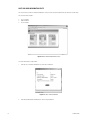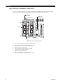
1
INSTALLATION MANUAL
®
DX9200 Digital Video
Recorder and
DX9100 Viewstation
C634M-D (12/04)
CONTENTS
Section
Page
IMPORTANT SAFETY INSTRUCTIONS . . . . . . . . . . . . . . . . . . . . . . . . . . . . . . . . . . . . . . . . . . . . . . . . . . . . . . . . . . . . . . . . . . . . . . . . . . . . . . . . . . . . . . . 7
REGULATORY NOTICES . . . . . . . . . . . . . . . . . . . . . . . . . . . . . . . . . . . . . . . . . . . . . . . . . . . . . . . . . . . . . . . . . . . . . . . . . . . . . . . . . . . . . . . . . . . . . . 8
DESCRIPTION . . . . . . . . . . . . . . . . . . . . . . . . . . . . . . . . . . . . . . . . . . . . . . . . . . . . . . . . . . . . . . . . . . . . . . . . . . . . . . . . . . . . . . . . . . . . . . . . . . . . . . . . . .
MODELS . . . . . . . . . . . . . . . . . . . . . . . . . . . . . . . . . . . . . . . . . . . . . . . . . . . . . . . . . . . . . . . . . . . . . . . . . . . . . . . . . . . . . . . . . . . . . . . . . . . . . . . . .
FRONT VIEW (RECORDER) . . . . . . . . . . . . . . . . . . . . . . . . . . . . . . . . . . . . . . . . . . . . . . . . . . . . . . . . . . . . . . . . . . . . . . . . . . . . . . . . . . . . . . . . . . . .
BACK VIEW (RECORDER) . . . . . . . . . . . . . . . . . . . . . . . . . . . . . . . . . . . . . . . . . . . . . . . . . . . . . . . . . . . . . . . . . . . . . . . . . . . . . . . . . . . . . . . . . . . . .
FRONT VIEW (VIEWSTATION) . . . . . . . . . . . . . . . . . . . . . . . . . . . . . . . . . . . . . . . . . . . . . . . . . . . . . . . . . . . . . . . . . . . . . . . . . . . . . . . . . . . . . . . . .
BACK VIEW (VIEWSTATION) . . . . . . . . . . . . . . . . . . . . . . . . . . . . . . . . . . . . . . . . . . . . . . . . . . . . . . . . . . . . . . . . . . . . . . . . . . . . . . . . . . . . . . . . . .
9
10
11
12
13
14
INSTALLATION . . . . . . . . . . . . . . . . . . . . . . . . . . . . . . . . . . . . . . . . . . . . . . . . . . . . . . . . . . . . . . . . . . . . . . . . . . . . . . . . . . . . . . . . . . . . . . . . . . . . . . . . .
INSTALLATION GUIDELINES . . . . . . . . . . . . . . . . . . . . . . . . . . . . . . . . . . . . . . . . . . . . . . . . . . . . . . . . . . . . . . . . . . . . . . . . . . . . . . . . . . . . . . . . . .
MOUNTING . . . . . . . . . . . . . . . . . . . . . . . . . . . . . . . . . . . . . . . . . . . . . . . . . . . . . . . . . . . . . . . . . . . . . . . . . . . . . . . . . . . . . . . . . . . . . . . . . . . . . . .
CONNECTIONS . . . . . . . . . . . . . . . . . . . . . . . . . . . . . . . . . . . . . . . . . . . . . . . . . . . . . . . . . . . . . . . . . . . . . . . . . . . . . . . . . . . . . . . . . . . . . . . . . . . .
POWER UP THE EQUIPMENT . . . . . . . . . . . . . . . . . . . . . . . . . . . . . . . . . . . . . . . . . . . . . . . . . . . . . . . . . . . . . . . . . . . . . . . . . . . . . . . . . . . . . . . . .
15
16
17
19
21
PROGRAMMING . . . . . . . . . . . . . . . . . . . . . . . . . . . . . . . . . . . . . . . . . . . . . . . . . . . . . . . . . . . . . . . . . . . . . . . . . . . . . . . . . . . . . . . . . . . . . . . . . . . . . . . .
VIEWSTATION NETWORK CONFIGURATION . . . . . . . . . . . . . . . . . . . . . . . . . . . . . . . . . . . . . . . . . . . . . . . . . . . . . . . . . . . . . . . . . . . . . . . . . . . . .
CHANGING THE VIEWSTATION’S IDENTIFICATION . . . . . . . . . . . . . . . . . . . . . . . . . . . . . . . . . . . . . . . . . . . . . . . . . . . . . . . . . . . . . . . . . . .
CHANGING THE VIEWSTATION’S IP ADDRESS AND SUBNET MASK . . . . . . . . . . . . . . . . . . . . . . . . . . . . . . . . . . . . . . . . . . . . . . . . . . . . .
CHANGING THE RECORDER’S IDENTIFICATION . . . . . . . . . . . . . . . . . . . . . . . . . . . . . . . . . . . . . . . . . . . . . . . . . . . . . . . . . . . . . . . . . . . . . . . . . . .
TIME SYNCHRONIZATION . . . . . . . . . . . . . . . . . . . . . . . . . . . . . . . . . . . . . . . . . . . . . . . . . . . . . . . . . . . . . . . . . . . . . . . . . . . . . . . . . . . . . . . . . . . .
SETTING DATE/TIME PROPERTIES . . . . . . . . . . . . . . . . . . . . . . . . . . . . . . . . . . . . . . . . . . . . . . . . . . . . . . . . . . . . . . . . . . . . . . . . . . . . . . . . . . . . .
CLIENT CONFIGURATION UTILITY . . . . . . . . . . . . . . . . . . . . . . . . . . . . . . . . . . . . . . . . . . . . . . . . . . . . . . . . . . . . . . . . . . . . . . . . . . . . . . . . . . . . . .
RECORDER INITIALIZATION OPTIONS . . . . . . . . . . . . . . . . . . . . . . . . . . . . . . . . . . . . . . . . . . . . . . . . . . . . . . . . . . . . . . . . . . . . . . . . . . . . . . . . . .
SERVER STATE . . . . . . . . . . . . . . . . . . . . . . . . . . . . . . . . . . . . . . . . . . . . . . . . . . . . . . . . . . . . . . . . . . . . . . . . . . . . . . . . . . . . . . . . . . . . . . . . . . . . .
ADVANCED RECORDER OPTIONS . . . . . . . . . . . . . . . . . . . . . . . . . . . . . . . . . . . . . . . . . . . . . . . . . . . . . . . . . . . . . . . . . . . . . . . . . . . . . . . . . . . . . .
DATABASE BACKUP AND REPAIR . . . . . . . . . . . . . . . . . . . . . . . . . . . . . . . . . . . . . . . . . . . . . . . . . . . . . . . . . . . . . . . . . . . . . . . . . . . . . . . . . . . . . .
DATABASE RESTORATION . . . . . . . . . . . . . . . . . . . . . . . . . . . . . . . . . . . . . . . . . . . . . . . . . . . . . . . . . . . . . . . . . . . . . . . . . . . . . . . . . . . . . . . . . . .
RAID MANAGER UTILITY . . . . . . . . . . . . . . . . . . . . . . . . . . . . . . . . . . . . . . . . . . . . . . . . . . . . . . . . . . . . . . . . . . . . . . . . . . . . . . . . . . . . . . . . . . . .
DISABLING THE RAID MANAGER GATEWAY . . . . . . . . . . . . . . . . . . . . . . . . . . . . . . . . . . . . . . . . . . . . . . . . . . . . . . . . . . . . . . . . . . . . . . . .
RAID MANAGER GATEWAY CONFIGURATION . . . . . . . . . . . . . . . . . . . . . . . . . . . . . . . . . . . . . . . . . . . . . . . . . . . . . . . . . . . . . . . . . . . . . . .
GATEWAY CONFIGURATION SETTINGS . . . . . . . . . . . . . . . . . . . . . . . . . . . . . . . . . . . . . . . . . . . . . . . . . . . . . . . . . . . . . . . . . . . . . . . . . . . .
EVENT NOTIFICATION . . . . . . . . . . . . . . . . . . . . . . . . . . . . . . . . . . . . . . . . . . . . . . . . . . . . . . . . . . . . . . . . . . . . . . . . . . . . . . . . . . . . . .
NETSEND SETTING . . . . . . . . . . . . . . . . . . . . . . . . . . . . . . . . . . . . . . . . . . . . . . . . . . . . . . . . . . . . . . . . . . . . . . . . . . . . . . . . . . . . . . . .
VIEWSTATION IP ADDRESS . . . . . . . . . . . . . . . . . . . . . . . . . . . . . . . . . . . . . . . . . . . . . . . . . . . . . . . . . . . . . . . . . . . . . . . . . . . . . . . . . . . . . .
RAID MANAGER HOME PAGE . . . . . . . . . . . . . . . . . . . . . . . . . . . . . . . . . . . . . . . . . . . . . . . . . . . . . . . . . . . . . . . . . . . . . . . . . . . . . . . . . . . . . . . .
DISK INFORMATION PLATE . . . . . . . . . . . . . . . . . . . . . . . . . . . . . . . . . . . . . . . . . . . . . . . . . . . . . . . . . . . . . . . . . . . . . . . . . . . . . . . . . . . . . .
HOST AND RAID INFORMATION PLATE . . . . . . . . . . . . . . . . . . . . . . . . . . . . . . . . . . . . . . . . . . . . . . . . . . . . . . . . . . . . . . . . . . . . . . . . . . . . .
STATUS PLATE . . . . . . . . . . . . . . . . . . . . . . . . . . . . . . . . . . . . . . . . . . . . . . . . . . . . . . . . . . . . . . . . . . . . . . . . . . . . . . . . . . . . . . . . . . . . . . . .
CAMERA RECORDING PROPERTIES . . . . . . . . . . . . . . . . . . . . . . . . . . . . . . . . . . . . . . . . . . . . . . . . . . . . . . . . . . . . . . . . . . . . . . . . . . . . . . . . . . . .
CONTINUOUS RECORDING SCHEDULE . . . . . . . . . . . . . . . . . . . . . . . . . . . . . . . . . . . . . . . . . . . . . . . . . . . . . . . . . . . . . . . . . . . . . . . . . . . . .
DAILY RECORDING SCHEDULE . . . . . . . . . . . . . . . . . . . . . . . . . . . . . . . . . . . . . . . . . . . . . . . . . . . . . . . . . . . . . . . . . . . . . . . . . . . . . . . . . . .
WEEKLY RECORDING SCHEDULE . . . . . . . . . . . . . . . . . . . . . . . . . . . . . . . . . . . . . . . . . . . . . . . . . . . . . . . . . . . . . . . . . . . . . . . . . . . . . . . . .
MOTION DETECTION . . . . . . . . . . . . . . . . . . . . . . . . . . . . . . . . . . . . . . . . . . . . . . . . . . . . . . . . . . . . . . . . . . . . . . . . . . . . . . . . . . . . . . . . . . .
CHANNEL SETUP . . . . . . . . . . . . . . . . . . . . . . . . . . . . . . . . . . . . . . . . . . . . . . . . . . . . . . . . . . . . . . . . . . . . . . . . . . . . . . . . . . . . . . . . . . . . . .
DEFINING USERS . . . . . . . . . . . . . . . . . . . . . . . . . . . . . . . . . . . . . . . . . . . . . . . . . . . . . . . . . . . . . . . . . . . . . . . . . . . . . . . . . . . . . . . . . . . . . . . . . .
22
22
23
24
26
27
28
29
31
33
35
35
36
45
45
45
48
48
49
50
52
54
56
57
58
60
60
62
63
64
66
ADVANCED FEATURES . . . . . . . . . . . . . . . . . . . . . . . . . . . . . . . . . . . . . . . . . . . . . . . . . . . . . . . . . . . . . . . . . . . . . . . . . . . . . . . . . . . . . . . . . . . . . . . . . . .
I/O INTERFACE . . . . . . . . . . . . . . . . . . . . . . . . . . . . . . . . . . . . . . . . . . . . . . . . . . . . . . . . . . . . . . . . . . . . . . . . . . . . . . . . . . . . . . . . . . . . . . . . . . . . .
I/O HANDLER . . . . . . . . . . . . . . . . . . . . . . . . . . . . . . . . . . . . . . . . . . . . . . . . . . . . . . . . . . . . . . . . . . . . . . . . . . . . . . . . . . . . . . . . . . . . . . . . .
I/O MANAGER . . . . . . . . . . . . . . . . . . . . . . . . . . . . . . . . . . . . . . . . . . . . . . . . . . . . . . . . . . . . . . . . . . . . . . . . . . . . . . . . . . . . . . . . . . . . . . . .
CONNECTING AN ALARM UNIT . . . . . . . . . . . . . . . . . . . . . . . . . . . . . . . . . . . . . . . . . . . . . . . . . . . . . . . . . . . . . . . . . . . . . . . . . . . . . . . . . . . . . . .
ALARM UNIT CONFIGURATION . . . . . . . . . . . . . . . . . . . . . . . . . . . . . . . . . . . . . . . . . . . . . . . . . . . . . . . . . . . . . . . . . . . . . . . . . . . . . . . . . . .
I/O MANAGER FOR ALARM UNIT . . . . . . . . . . . . . . . . . . . . . . . . . . . . . . . . . . . . . . . . . . . . . . . . . . . . . . . . . . . . . . . . . . . . . . . . . . . . .
CONNECTING A RELAY UNIT . . . . . . . . . . . . . . . . . . . . . . . . . . . . . . . . . . . . . . . . . . . . . . . . . . . . . . . . . . . . . . . . . . . . . . . . . . . . . . . . . . . . . . . . .
RELAY UNIT CONFIGURATION . . . . . . . . . . . . . . . . . . . . . . . . . . . . . . . . . . . . . . . . . . . . . . . . . . . . . . . . . . . . . . . . . . . . . . . . . . . . . . . . . . . .
I/O MANAGER FOR RELAY UNIT . . . . . . . . . . . . . . . . . . . . . . . . . . . . . . . . . . . . . . . . . . . . . . . . . . . . . . . . . . . . . . . . . . . . . . . . . . . . . .
68
68
68
68
69
70
72
75
76
78
2
C634M-D (12/04)
CONNECTING A CM9760-CC1 . . . . . . . . . . . . . . . . . . . . . . . . . . . . . . . . . . . . . . . . . . . . . . . . . . . . . . . . . . . . . . . . . . . . . . . . . . . . . . . . . . . . . . . .
CONNECTING A CM6800 . . . . . . . . . . . . . . . . . . . . . . . . . . . . . . . . . . . . . . . . . . . . . . . . . . . . . . . . . . . . . . . . . . . . . . . . . . . . . . . . . . . . . . . . . . . .
DATA TRANSLATOR CONFIGURATION . . . . . . . . . . . . . . . . . . . . . . . . . . . . . . . . . . . . . . . . . . . . . . . . . . . . . . . . . . . . . . . . . . . . . . . . . . . . . .
I/O MANAGER FOR DATA TRANSLATOR . . . . . . . . . . . . . . . . . . . . . . . . . . . . . . . . . . . . . . . . . . . . . . . . . . . . . . . . . . . . . . . . . . . . . . .
DVR MANAGEMENT . . . . . . . . . . . . . . . . . . . . . . . . . . . . . . . . . . . . . . . . . . . . . . . . . . . . . . . . . . . . . . . . . . . . . . . . . . . . . . . . . . . . . . . . . . . . . . . .
DATA TRANSLATOR CONNECTIONS . . . . . . . . . . . . . . . . . . . . . . . . . . . . . . . . . . . . . . . . . . . . . . . . . . . . . . . . . . . . . . . . . . . . . . . . . . . . . . .
CONFIGURING THE DATA TRANSLATOR . . . . . . . . . . . . . . . . . . . . . . . . . . . . . . . . . . . . . . . . . . . . . . . . . . . . . . . . . . . . . . . . . . . . . . . . . . . .
RELAY UNIT CONNECTIONS . . . . . . . . . . . . . . . . . . . . . . . . . . . . . . . . . . . . . . . . . . . . . . . . . . . . . . . . . . . . . . . . . . . . . . . . . . . . . . . . . . . . .
CONFIGURING THE RELAY UNIT . . . . . . . . . . . . . . . . . . . . . . . . . . . . . . . . . . . . . . . . . . . . . . . . . . . . . . . . . . . . . . . . . . . . . . . . . . . . . . . . . .
FOREIGN LANGUAGE PROGRAMMING . . . . . . . . . . . . . . . . . . . . . . . . . . . . . . . . . . . . . . . . . . . . . . . . . . . . . . . . . . . . . . . . . . . . . . . . . . . . . . . . .
80
81
82
84
86
86
87
89
90
92
SERVICE . . . . . . . . . . . . . . . . . . . . . . . . . . . . . . . . . . . . . . . . . . . . . . . . . . . . . . . . . . . . . . . . . . . . . . . . . . . . . . . . . . . . . . . . . . . . . . . . . . . . . . . . . . . . . . 94
HOW TO REPLACE A RECORDER’S POWER SUPPLY . . . . . . . . . . . . . . . . . . . . . . . . . . . . . . . . . . . . . . . . . . . . . . . . . . . . . . . . . . . . . . . . . . . . . . . 94
HOW TO REPLACE A RECORDER’S RAID 1 DRIVE . . . . . . . . . . . . . . . . . . . . . . . . . . . . . . . . . . . . . . . . . . . . . . . . . . . . . . . . . . . . . . . . . . . . . . . . . 95
SPECIFICATIONS . . . . . . . . . . . . . . . . . . . . . . . . . . . . . . . . . . . . . . . . . . . . . . . . . . . . . . . . . . . . . . . . . . . . . . . . . . . . . . . . . . . . . . . . . . . . . . . . . . . . . . . 100
C634M-D (12/04)
3
LIST OF ILLUSTRATIONS
Figure
1.
2.
3.
4.
5.
6.
7.
8.
9.
10.
11.
12.
13.
14.
15.
16.
17.
18.
19.
20.
21.
22.
23.
24.
25.
26.
27.
28.
29.
30.
31.
32.
33.
34.
35.
36.
37.
38.
39.
40.
41.
42.
43.
44.
45.
46.
47.
48.
49.
50.
51.
52.
53.
54.
55.
56.
57.
58.
4
Page
DX9200 System Overview . . . . . . . . . . . . . . . . . . . . . . . . . . . . . . . . . . . . . . . . . . . . . . . . . . . . . . . . . . . . . . . . . . . . . . . . . . . . . . . . . . . . . . .
Front View of Recorder . . . . . . . . . . . . . . . . . . . . . . . . . . . . . . . . . . . . . . . . . . . . . . . . . . . . . . . . . . . . . . . . . . . . . . . . . . . . . . . . . . . . . . . . . .
Back View of Recorder . . . . . . . . . . . . . . . . . . . . . . . . . . . . . . . . . . . . . . . . . . . . . . . . . . . . . . . . . . . . . . . . . . . . . . . . . . . . . . . . . . . . . . . . . .
Front View of Viewstation . . . . . . . . . . . . . . . . . . . . . . . . . . . . . . . . . . . . . . . . . . . . . . . . . . . . . . . . . . . . . . . . . . . . . . . . . . . . . . . . . . . . . . .
Back View of Viewstation . . . . . . . . . . . . . . . . . . . . . . . . . . . . . . . . . . . . . . . . . . . . . . . . . . . . . . . . . . . . . . . . . . . . . . . . . . . . . . . . . . . . . . .
DX9200 Rack Mount Installation . . . . . . . . . . . . . . . . . . . . . . . . . . . . . . . . . . . . . . . . . . . . . . . . . . . . . . . . . . . . . . . . . . . . . . . . . . . . . . . . . .
37-Pin Connectors . . . . . . . . . . . . . . . . . . . . . . . . . . . . . . . . . . . . . . . . . . . . . . . . . . . . . . . . . . . . . . . . . . . . . . . . . . . . . . . . . . . . . . . . . . . . .
HASP Key Message . . . . . . . . . . . . . . . . . . . . . . . . . . . . . . . . . . . . . . . . . . . . . . . . . . . . . . . . . . . . . . . . . . . . . . . . . . . . . . . . . . . . . . . . . . . .
System Connections . . . . . . . . . . . . . . . . . . . . . . . . . . . . . . . . . . . . . . . . . . . . . . . . . . . . . . . . . . . . . . . . . . . . . . . . . . . . . . . . . . . . . . . . . . . .
Viewstation Network Identification Page . . . . . . . . . . . . . . . . . . . . . . . . . . . . . . . . . . . . . . . . . . . . . . . . . . . . . . . . . . . . . . . . . . . . . . . . . . .
Viewstation Identification Changes Dialog Box . . . . . . . . . . . . . . . . . . . . . . . . . . . . . . . . . . . . . . . . . . . . . . . . . . . . . . . . . . . . . . . . . . . . . . .
Viewstation Network Connections Window . . . . . . . . . . . . . . . . . . . . . . . . . . . . . . . . . . . . . . . . . . . . . . . . . . . . . . . . . . . . . . . . . . . . . . . . .
Viewstation Local Area Connection Status Dialog Box . . . . . . . . . . . . . . . . . . . . . . . . . . . . . . . . . . . . . . . . . . . . . . . . . . . . . . . . . . . . . . . . .
Viewstation Local Area Connection Properties Dialog Box . . . . . . . . . . . . . . . . . . . . . . . . . . . . . . . . . . . . . . . . . . . . . . . . . . . . . . . . . . . . . .
Viewstation Internet Protocol (TCP/IP) Properties Dialog Box . . . . . . . . . . . . . . . . . . . . . . . . . . . . . . . . . . . . . . . . . . . . . . . . . . . . . . . . . . . .
Server Configuration Utility Dialog Box . . . . . . . . . . . . . . . . . . . . . . . . . . . . . . . . . . . . . . . . . . . . . . . . . . . . . . . . . . . . . . . . . . . . . . . . . . . . .
Server Identification Dialog Box . . . . . . . . . . . . . . . . . . . . . . . . . . . . . . . . . . . . . . . . . . . . . . . . . . . . . . . . . . . . . . . . . . . . . . . . . . . . . . . . . .
Date & Time Page . . . . . . . . . . . . . . . . . . . . . . . . . . . . . . . . . . . . . . . . . . . . . . . . . . . . . . . . . . . . . . . . . . . . . . . . . . . . . . . . . . . . . . . . . . . . . .
Time Zone Page . . . . . . . . . . . . . . . . . . . . . . . . . . . . . . . . . . . . . . . . . . . . . . . . . . . . . . . . . . . . . . . . . . . . . . . . . . . . . . . . . . . . . . . . . . . . . . .
Client Configuration Login Dialog Box . . . . . . . . . . . . . . . . . . . . . . . . . . . . . . . . . . . . . . . . . . . . . . . . . . . . . . . . . . . . . . . . . . . . . . . . . . . . . .
Client Configuration Utility . . . . . . . . . . . . . . . . . . . . . . . . . . . . . . . . . . . . . . . . . . . . . . . . . . . . . . . . . . . . . . . . . . . . . . . . . . . . . . . . . . . . . . .
Export to Server Dialog Box . . . . . . . . . . . . . . . . . . . . . . . . . . . . . . . . . . . . . . . . . . . . . . . . . . . . . . . . . . . . . . . . . . . . . . . . . . . . . . . . . . . . . .
DX9216H Frame Rate and Resolution . . . . . . . . . . . . . . . . . . . . . . . . . . . . . . . . . . . . . . . . . . . . . . . . . . . . . . . . . . . . . . . . . . . . . . . . . . . . . .
DX9208F Frame Rate and Resolution . . . . . . . . . . . . . . . . . . . . . . . . . . . . . . . . . . . . . . . . . . . . . . . . . . . . . . . . . . . . . . . . . . . . . . . . . . . . . . .
License Information Dialog Box . . . . . . . . . . . . . . . . . . . . . . . . . . . . . . . . . . . . . . . . . . . . . . . . . . . . . . . . . . . . . . . . . . . . . . . . . . . . . . . . . . .
Server State . . . . . . . . . . . . . . . . . . . . . . . . . . . . . . . . . . . . . . . . . . . . . . . . . . . . . . . . . . . . . . . . . . . . . . . . . . . . . . . . . . . . . . . . . . . . . . . . . .
Configuration Options . . . . . . . . . . . . . . . . . . . . . . . . . . . . . . . . . . . . . . . . . . . . . . . . . . . . . . . . . . . . . . . . . . . . . . . . . . . . . . . . . . . . . . . . . .
Error Alert . . . . . . . . . . . . . . . . . . . . . . . . . . . . . . . . . . . . . . . . . . . . . . . . . . . . . . . . . . . . . . . . . . . . . . . . . . . . . . . . . . . . . . . . . . . . . . . . . . . .
Advanced Options . . . . . . . . . . . . . . . . . . . . . . . . . . . . . . . . . . . . . . . . . . . . . . . . . . . . . . . . . . . . . . . . . . . . . . . . . . . . . . . . . . . . . . . . . . . . .
Database Backup and Repair Confirmation . . . . . . . . . . . . . . . . . . . . . . . . . . . . . . . . . . . . . . . . . . . . . . . . . . . . . . . . . . . . . . . . . . . . . . . . . .
System Tray . . . . . . . . . . . . . . . . . . . . . . . . . . . . . . . . . . . . . . . . . . . . . . . . . . . . . . . . . . . . . . . . . . . . . . . . . . . . . . . . . . . . . . . . . . . . . . . . . .
Server Service Manager Window . . . . . . . . . . . . . . . . . . . . . . . . . . . . . . . . . . . . . . . . . . . . . . . . . . . . . . . . . . . . . . . . . . . . . . . . . . . . . . . . .
Stop SQL Dialog Box 1 . . . . . . . . . . . . . . . . . . . . . . . . . . . . . . . . . . . . . . . . . . . . . . . . . . . . . . . . . . . . . . . . . . . . . . . . . . . . . . . . . . . . . . . . . .
Stop SQL Dialog Box 2 . . . . . . . . . . . . . . . . . . . . . . . . . . . . . . . . . . . . . . . . . . . . . . . . . . . . . . . . . . . . . . . . . . . . . . . . . . . . . . . . . . . . . . . . . .
Start/Continue Window . . . . . . . . . . . . . . . . . . . . . . . . . . . . . . . . . . . . . . . . . . . . . . . . . . . . . . . . . . . . . . . . . . . . . . . . . . . . . . . . . . . . . . . . .
My Computer Window . . . . . . . . . . . . . . . . . . . . . . . . . . . . . . . . . . . . . . . . . . . . . . . . . . . . . . . . . . . . . . . . . . . . . . . . . . . . . . . . . . . . . . . . . .
Databases Window . . . . . . . . . . . . . . . . . . . . . . . . . . . . . . . . . . . . . . . . . . . . . . . . . . . . . . . . . . . . . . . . . . . . . . . . . . . . . . . . . . . . . . . . . . . .
Rename MSSQL . . . . . . . . . . . . . . . . . . . . . . . . . . . . . . . . . . . . . . . . . . . . . . . . . . . . . . . . . . . . . . . . . . . . . . . . . . . . . . . . . . . . . . . . . . . . . . .
C Drive Databases Window . . . . . . . . . . . . . . . . . . . . . . . . . . . . . . . . . . . . . . . . . . . . . . . . . . . . . . . . . . . . . . . . . . . . . . . . . . . . . . . . . . . . . .
MSSQL Folders . . . . . . . . . . . . . . . . . . . . . . . . . . . . . . . . . . . . . . . . . . . . . . . . . . . . . . . . . . . . . . . . . . . . . . . . . . . . . . . . . . . . . . . . . . . . . . . .
Start/Continue Window . . . . . . . . . . . . . . . . . . . . . . . . . . . . . . . . . . . . . . . . . . . . . . . . . . . . . . . . . . . . . . . . . . . . . . . . . . . . . . . . . . . . . . . . .
Database Backups Window . . . . . . . . . . . . . . . . . . . . . . . . . . . . . . . . . . . . . . . . . . . . . . . . . . . . . . . . . . . . . . . . . . . . . . . . . . . . . . . . . . . . . .
Explorer Windows . . . . . . . . . . . . . . . . . . . . . . . . . . . . . . . . . . . . . . . . . . . . . . . . . . . . . . . . . . . . . . . . . . . . . . . . . . . . . . . . . . . . . . . . . . . . .
Restore Utility Dialog Box . . . . . . . . . . . . . . . . . . . . . . . . . . . . . . . . . . . . . . . . . . . . . . . . . . . . . . . . . . . . . . . . . . . . . . . . . . . . . . . . . . . . . . .
System Tray . . . . . . . . . . . . . . . . . . . . . . . . . . . . . . . . . . . . . . . . . . . . . . . . . . . . . . . . . . . . . . . . . . . . . . . . . . . . . . . . . . . . . . . . . . . . . . . . . .
Server Service Manager Window . . . . . . . . . . . . . . . . . . . . . . . . . . . . . . . . . . . . . . . . . . . . . . . . . . . . . . . . . . . . . . . . . . . . . . . . . . . . . . . . .
Stop SQL Dialog Box 1 . . . . . . . . . . . . . . . . . . . . . . . . . . . . . . . . . . . . . . . . . . . . . . . . . . . . . . . . . . . . . . . . . . . . . . . . . . . . . . . . . . . . . . . . . .
Stop SQL Dialog Box 2 . . . . . . . . . . . . . . . . . . . . . . . . . . . . . . . . . . . . . . . . . . . . . . . . . . . . . . . . . . . . . . . . . . . . . . . . . . . . . . . . . . . . . . . . . .
Start/Continue Window . . . . . . . . . . . . . . . . . . . . . . . . . . . . . . . . . . . . . . . . . . . . . . . . . . . . . . . . . . . . . . . . . . . . . . . . . . . . . . . . . . . . . . . . .
Replace Database Dialog Box . . . . . . . . . . . . . . . . . . . . . . . . . . . . . . . . . . . . . . . . . . . . . . . . . . . . . . . . . . . . . . . . . . . . . . . . . . . . . . . . . . . .
Restore Confirmation Dialog Box . . . . . . . . . . . . . . . . . . . . . . . . . . . . . . . . . . . . . . . . . . . . . . . . . . . . . . . . . . . . . . . . . . . . . . . . . . . . . . . . . .
Operation Completed Dialog Box . . . . . . . . . . . . . . . . . . . . . . . . . . . . . . . . . . . . . . . . . . . . . . . . . . . . . . . . . . . . . . . . . . . . . . . . . . . . . . . . . .
Maintenance Dialog Box . . . . . . . . . . . . . . . . . . . . . . . . . . . . . . . . . . . . . . . . . . . . . . . . . . . . . . . . . . . . . . . . . . . . . . . . . . . . . . . . . . . . . . . .
Finished Scan Dialog Box . . . . . . . . . . . . . . . . . . . . . . . . . . . . . . . . . . . . . . . . . . . . . . . . . . . . . . . . . . . . . . . . . . . . . . . . . . . . . . . . . . . . . . . .
Finished Merging Dialog Box . . . . . . . . . . . . . . . . . . . . . . . . . . . . . . . . . . . . . . . . . . . . . . . . . . . . . . . . . . . . . . . . . . . . . . . . . . . . . . . . . . . . .
Raid Manager Gateway Configuration Window . . . . . . . . . . . . . . . . . . . . . . . . . . . . . . . . . . . . . . . . . . . . . . . . . . . . . . . . . . . . . . . . . . . . . .
Default Server Information Window . . . . . . . . . . . . . . . . . . . . . . . . . . . . . . . . . . . . . . . . . . . . . . . . . . . . . . . . . . . . . . . . . . . . . . . . . . . . . . .
Edit Server Window . . . . . . . . . . . . . . . . . . . . . . . . . . . . . . . . . . . . . . . . . . . . . . . . . . . . . . . . . . . . . . . . . . . . . . . . . . . . . . . . . . . . . . . . . . . .
9
11
12
13
14
18
19
19
20
23
23
24
24
25
25
26
26
28
28
29
29
30
31
31
31
33
34
34
35
35
36
36
36
36
37
37
38
38
39
39
40
40
41
41
41
42
42
42
42
43
43
43
43
44
44
45
46
46
C634M-D (12/04)
59.
60.
61.
62.
63.
64.
65.
66.
67.
68.
69.
70.
71.
72.
73.
74.
75.
76.
77.
78.
79.
80.
81.
82.
83.
84.
85.
86.
87.
88.
89.
90.
91.
92.
93.
94.
95.
96.
97.
98.
99.
100.
101.
102.
103.
104.
105.
106.
107.
108.
109.
110.
111.
112.
113.
114.
115.
116.
117.
118.
119.
120.
121.
Add Server Window . . . . . . . . . . . . . . . . . . . . . . . . . . . . . . . . . . . . . . . . . . . . . . . . . . . . . . . . . . . . . . . . . . . . . . . . . . . . . . . . . . . . . . . . . . . .
Edit Group Window . . . . . . . . . . . . . . . . . . . . . . . . . . . . . . . . . . . . . . . . . . . . . . . . . . . . . . . . . . . . . . . . . . . . . . . . . . . . . . . . . . . . . . . . . . . .
Add Group Window . . . . . . . . . . . . . . . . . . . . . . . . . . . . . . . . . . . . . . . . . . . . . . . . . . . . . . . . . . . . . . . . . . . . . . . . . . . . . . . . . . . . . . . . . . . .
Event Notification Page . . . . . . . . . . . . . . . . . . . . . . . . . . . . . . . . . . . . . . . . . . . . . . . . . . . . . . . . . . . . . . . . . . . . . . . . . . . . . . . . . . . . . . . . .
NetSend Setting Page . . . . . . . . . . . . . . . . . . . . . . . . . . . . . . . . . . . . . . . . . . . . . . . . . . . . . . . . . . . . . . . . . . . . . . . . . . . . . . . . . . . . . . . . . .
Internet Properties Window . . . . . . . . . . . . . . . . . . . . . . . . . . . . . . . . . . . . . . . . . . . . . . . . . . . . . . . . . . . . . . . . . . . . . . . . . . . . . . . . . . . . . .
Internet Information Services Window . . . . . . . . . . . . . . . . . . . . . . . . . . . . . . . . . . . . . . . . . . . . . . . . . . . . . . . . . . . . . . . . . . . . . . . . . . . . .
Default Web Site Properties . . . . . . . . . . . . . . . . . . . . . . . . . . . . . . . . . . . . . . . . . . . . . . . . . . . . . . . . . . . . . . . . . . . . . . . . . . . . . . . . . . . . .
Raid Manager Home Page . . . . . . . . . . . . . . . . . . . . . . . . . . . . . . . . . . . . . . . . . . . . . . . . . . . . . . . . . . . . . . . . . . . . . . . . . . . . . . . . . . . . . . .
Storage Information Window . . . . . . . . . . . . . . . . . . . . . . . . . . . . . . . . . . . . . . . . . . . . . . . . . . . . . . . . . . . . . . . . . . . . . . . . . . . . . . . . . . . . .
Controller Information Window . . . . . . . . . . . . . . . . . . . . . . . . . . . . . . . . . . . . . . . . . . . . . . . . . . . . . . . . . . . . . . . . . . . . . . . . . . . . . . . . . . .
No Hard Drive Information . . . . . . . . . . . . . . . . . . . . . . . . . . . . . . . . . . . . . . . . . . . . . . . . . . . . . . . . . . . . . . . . . . . . . . . . . . . . . . . . . . . . . . .
Configured Hard Drive Information . . . . . . . . . . . . . . . . . . . . . . . . . . . . . . . . . . . . . . . . . . . . . . . . . . . . . . . . . . . . . . . . . . . . . . . . . . . . . . . .
Newly Replaced Hard Drive Information . . . . . . . . . . . . . . . . . . . . . . . . . . . . . . . . . . . . . . . . . . . . . . . . . . . . . . . . . . . . . . . . . . . . . . . . . . . .
Spare Hard Drive Information . . . . . . . . . . . . . . . . . . . . . . . . . . . . . . . . . . . . . . . . . . . . . . . . . . . . . . . . . . . . . . . . . . . . . . . . . . . . . . . . . . . .
Host & Raid Information Screen . . . . . . . . . . . . . . . . . . . . . . . . . . . . . . . . . . . . . . . . . . . . . . . . . . . . . . . . . . . . . . . . . . . . . . . . . . . . . . . . . .
Host 1 Interface Details . . . . . . . . . . . . . . . . . . . . . . . . . . . . . . . . . . . . . . . . . . . . . . . . . . . . . . . . . . . . . . . . . . . . . . . . . . . . . . . . . . . . . . . . .
RAID Information Details . . . . . . . . . . . . . . . . . . . . . . . . . . . . . . . . . . . . . . . . . . . . . . . . . . . . . . . . . . . . . . . . . . . . . . . . . . . . . . . . . . . . . . . .
Host 2 Interface Details . . . . . . . . . . . . . . . . . . . . . . . . . . . . . . . . . . . . . . . . . . . . . . . . . . . . . . . . . . . . . . . . . . . . . . . . . . . . . . . . . . . . . . . . .
Status Plate . . . . . . . . . . . . . . . . . . . . . . . . . . . . . . . . . . . . . . . . . . . . . . . . . . . . . . . . . . . . . . . . . . . . . . . . . . . . . . . . . . . . . . . . . . . . . . . . . .
Camera Properties Dialog Box . . . . . . . . . . . . . . . . . . . . . . . . . . . . . . . . . . . . . . . . . . . . . . . . . . . . . . . . . . . . . . . . . . . . . . . . . . . . . . . . . . . .
Select Channel Dialog Box . . . . . . . . . . . . . . . . . . . . . . . . . . . . . . . . . . . . . . . . . . . . . . . . . . . . . . . . . . . . . . . . . . . . . . . . . . . . . . . . . . . . . . .
Continuous Recording Schedule Page . . . . . . . . . . . . . . . . . . . . . . . . . . . . . . . . . . . . . . . . . . . . . . . . . . . . . . . . . . . . . . . . . . . . . . . . . . . . . .
Continuous Daily Recording Schedule Page . . . . . . . . . . . . . . . . . . . . . . . . . . . . . . . . . . . . . . . . . . . . . . . . . . . . . . . . . . . . . . . . . . . . . . . . .
Daily Event Recording Page . . . . . . . . . . . . . . . . . . . . . . . . . . . . . . . . . . . . . . . . . . . . . . . . . . . . . . . . . . . . . . . . . . . . . . . . . . . . . . . . . . . . . .
Continuous Weekly Recording Schedule Page . . . . . . . . . . . . . . . . . . . . . . . . . . . . . . . . . . . . . . . . . . . . . . . . . . . . . . . . . . . . . . . . . . . . . . .
Weekly Event Recording Schedule Page . . . . . . . . . . . . . . . . . . . . . . . . . . . . . . . . . . . . . . . . . . . . . . . . . . . . . . . . . . . . . . . . . . . . . . . . . . . .
Motion Detection Page . . . . . . . . . . . . . . . . . . . . . . . . . . . . . . . . . . . . . . . . . . . . . . . . . . . . . . . . . . . . . . . . . . . . . . . . . . . . . . . . . . . . . . . . .
Camera Video Setup Page . . . . . . . . . . . . . . . . . . . . . . . . . . . . . . . . . . . . . . . . . . . . . . . . . . . . . . . . . . . . . . . . . . . . . . . . . . . . . . . . . . . . . . .
User Access Dialog Box . . . . . . . . . . . . . . . . . . . . . . . . . . . . . . . . . . . . . . . . . . . . . . . . . . . . . . . . . . . . . . . . . . . . . . . . . . . . . . . . . . . . . . . . .
User Manager Dialog Box . . . . . . . . . . . . . . . . . . . . . . . . . . . . . . . . . . . . . . . . . . . . . . . . . . . . . . . . . . . . . . . . . . . . . . . . . . . . . . . . . . . . . . .
Connecting a CM9760-ALM . . . . . . . . . . . . . . . . . . . . . . . . . . . . . . . . . . . . . . . . . . . . . . . . . . . . . . . . . . . . . . . . . . . . . . . . . . . . . . . . . . . . . .
Alarm I/O Handler Configuration Dialog Box . . . . . . . . . . . . . . . . . . . . . . . . . . . . . . . . . . . . . . . . . . . . . . . . . . . . . . . . . . . . . . . . . . . . . . . . .
CM9760 Alarm Driver Dialog Box . . . . . . . . . . . . . . . . . . . . . . . . . . . . . . . . . . . . . . . . . . . . . . . . . . . . . . . . . . . . . . . . . . . . . . . . . . . . . . . . .
Device 2 Alarm Driver Dialog Box . . . . . . . . . . . . . . . . . . . . . . . . . . . . . . . . . . . . . . . . . . . . . . . . . . . . . . . . . . . . . . . . . . . . . . . . . . . . . . . . .
CM9760 Alarm Configuration Dialog Box . . . . . . . . . . . . . . . . . . . . . . . . . . . . . . . . . . . . . . . . . . . . . . . . . . . . . . . . . . . . . . . . . . . . . . . . . . .
Dialog Box to ConExternal 1 Source . . . . . . . . . . . . . . . . . . . . . . . . . . . . . . . . . . . . . . . . . . . . . . . . . . . . . . . . . . . . . . . . . . . . . . . . . . . . . . .
Sample Configuration for External 1 Source . . . . . . . . . . . . . . . . . . . . . . . . . . . . . . . . . . . . . . . . . . . . . . . . . . . . . . . . . . . . . . . . . . . . . . . . .
Dialog Box to ConExternal 2 Source . . . . . . . . . . . . . . . . . . . . . . . . . . . . . . . . . . . . . . . . . . . . . . . . . . . . . . . . . . . . . . . . . . . . . . . . . . . . . . .
Connecting a CM9760-REL . . . . . . . . . . . . . . . . . . . . . . . . . . . . . . . . . . . . . . . . . . . . . . . . . . . . . . . . . . . . . . . . . . . . . . . . . . . . . . . . . . . . . . .
Relay I/O Handler Dialog Box . . . . . . . . . . . . . . . . . . . . . . . . . . . . . . . . . . . . . . . . . . . . . . . . . . . . . . . . . . . . . . . . . . . . . . . . . . . . . . . . . . . . .
CM9760 Relay Driver Dialog Box . . . . . . . . . . . . . . . . . . . . . . . . . . . . . . . . . . . . . . . . . . . . . . . . . . . . . . . . . . . . . . . . . . . . . . . . . . . . . . . . . .
Device 1 Relay Driver Dialog Box . . . . . . . . . . . . . . . . . . . . . . . . . . . . . . . . . . . . . . . . . . . . . . . . . . . . . . . . . . . . . . . . . . . . . . . . . . . . . . . . . .
CM9760 Relay Configuration Dialog Box . . . . . . . . . . . . . . . . . . . . . . . . . . . . . . . . . . . . . . . . . . . . . . . . . . . . . . . . . . . . . . . . . . . . . . . . . . . .
Relay Unit Step 3 Screen . . . . . . . . . . . . . . . . . . . . . . . . . . . . . . . . . . . . . . . . . . . . . . . . . . . . . . . . . . . . . . . . . . . . . . . . . . . . . . . . . . . . . . . .
Dialog Box to ConRelay Event Type . . . . . . . . . . . . . . . . . . . . . . . . . . . . . . . . . . . . . . . . . . . . . . . . . . . . . . . . . . . . . . . . . . . . . . . . . . . . . . . .
Connecting a CM9760-CC1 . . . . . . . . . . . . . . . . . . . . . . . . . . . . . . . . . . . . . . . . . . . . . . . . . . . . . . . . . . . . . . . . . . . . . . . . . . . . . . . . . . . . . .
Connecting a CM6800 . . . . . . . . . . . . . . . . . . . . . . . . . . . . . . . . . . . . . . . . . . . . . . . . . . . . . . . . . . . . . . . . . . . . . . . . . . . . . . . . . . . . . . . . . .
Data Translator I/O Handler Configuration Dialog Box . . . . . . . . . . . . . . . . . . . . . . . . . . . . . . . . . . . . . . . . . . . . . . . . . . . . . . . . . . . . . . . . .
CM9760 Data Translator Driver Dialog Box . . . . . . . . . . . . . . . . . . . . . . . . . . . . . . . . . . . . . . . . . . . . . . . . . . . . . . . . . . . . . . . . . . . . . . . . . .
Device 1 Data Translator Driver Dialog Box . . . . . . . . . . . . . . . . . . . . . . . . . . . . . . . . . . . . . . . . . . . . . . . . . . . . . . . . . . . . . . . . . . . . . . . . . .
CM9760 Relay Configuration Dialog Box . . . . . . . . . . . . . . . . . . . . . . . . . . . . . . . . . . . . . . . . . . . . . . . . . . . . . . . . . . . . . . . . . . . . . . . . . . . .
Dialog Box to ConData Translator . . . . . . . . . . . . . . . . . . . . . . . . . . . . . . . . . . . . . . . . . . . . . . . . . . . . . . . . . . . . . . . . . . . . . . . . . . . . . . . . .
Dialog Box to ConData Translator Event Type . . . . . . . . . . . . . . . . . . . . . . . . . . . . . . . . . . . . . . . . . . . . . . . . . . . . . . . . . . . . . . . . . . . . . . . .
Connecting a CM9760-DT for DVR Management . . . . . . . . . . . . . . . . . . . . . . . . . . . . . . . . . . . . . . . . . . . . . . . . . . . . . . . . . . . . . . . . . . . . .
Data Translator Configuration Dialog Box . . . . . . . . . . . . . . . . . . . . . . . . . . . . . . . . . . . . . . . . . . . . . . . . . . . . . . . . . . . . . . . . . . . . . . . . . . .
Data Translator Driver Dialog Box . . . . . . . . . . . . . . . . . . . . . . . . . . . . . . . . . . . . . . . . . . . . . . . . . . . . . . . . . . . . . . . . . . . . . . . . . . . . . . . . .
Data Translator Driver Settings Dialog Box . . . . . . . . . . . . . . . . . . . . . . . . . . . . . . . . . . . . . . . . . . . . . . . . . . . . . . . . . . . . . . . . . . . . . . . . . .
CM9760-DT Configuration . . . . . . . . . . . . . . . . . . . . . . . . . . . . . . . . . . . . . . . . . . . . . . . . . . . . . . . . . . . . . . . . . . . . . . . . . . . . . . . . . . . . . . .
Connecting a CM9760-REL for DVR Management . . . . . . . . . . . . . . . . . . . . . . . . . . . . . . . . . . . . . . . . . . . . . . . . . . . . . . . . . . . . . . . . . . . .
Relay Unit Configuration Dialog Box . . . . . . . . . . . . . . . . . . . . . . . . . . . . . . . . . . . . . . . . . . . . . . . . . . . . . . . . . . . . . . . . . . . . . . . . . . . . . . .
Relay Unit Driver Dialog Box . . . . . . . . . . . . . . . . . . . . . . . . . . . . . . . . . . . . . . . . . . . . . . . . . . . . . . . . . . . . . . . . . . . . . . . . . . . . . . . . . . . . .
Relay Unit Driver Settings Dialog Box . . . . . . . . . . . . . . . . . . . . . . . . . . . . . . . . . . . . . . . . . . . . . . . . . . . . . . . . . . . . . . . . . . . . . . . . . . . . . .
C634M-D (12/04)
46
47
47
48
49
50
50
51
52
53
53
54
55
55
55
56
56
57
57
57
58
59
59
60
61
62
62
63
64
66
66
69
70
70
71
71
72
73
74
75
76
76
77
77
78
79
80
81
82
82
83
83
84
85
86
87
87
87
88
89
90
90
90
5
122.
123.
124.
125.
126.
127.
128.
129.
130.
131.
132.
133.
134.
CM9760-REL Configuration Dialog Box . . . . . . . . . . . . . . . . . . . . . . . . . . . . . . . . . . . . . . . . . . . . . . . . . . . . . . . . . . . . . . . . . . . . . . . . . . . . .
Change System Location . . . . . . . . . . . . . . . . . . . . . . . . . . . . . . . . . . . . . . . . . . . . . . . . . . . . . . . . . . . . . . . . . . . . . . . . . . . . . . . . . . . . . . . .
Select System Location . . . . . . . . . . . . . . . . . . . . . . . . . . . . . . . . . . . . . . . . . . . . . . . . . . . . . . . . . . . . . . . . . . . . . . . . . . . . . . . . . . . . . . . . .
Power Supply Replacement . . . . . . . . . . . . . . . . . . . . . . . . . . . . . . . . . . . . . . . . . . . . . . . . . . . . . . . . . . . . . . . . . . . . . . . . . . . . . . . . . . . . . .
Raid Server Window . . . . . . . . . . . . . . . . . . . . . . . . . . . . . . . . . . . . . . . . . . . . . . . . . . . . . . . . . . . . . . . . . . . . . . . . . . . . . . . . . . . . . . . . . . .
Login Window . . . . . . . . . . . . . . . . . . . . . . . . . . . . . . . . . . . . . . . . . . . . . . . . . . . . . . . . . . . . . . . . . . . . . . . . . . . . . . . . . . . . . . . . . . . . . . . .
Remote Monitor Window . . . . . . . . . . . . . . . . . . . . . . . . . . . . . . . . . . . . . . . . . . . . . . . . . . . . . . . . . . . . . . . . . . . . . . . . . . . . . . . . . . . . . . . .
Fast Trak Window . . . . . . . . . . . . . . . . . . . . . . . . . . . . . . . . . . . . . . . . . . . . . . . . . . . . . . . . . . . . . . . . . . . . . . . . . . . . . . . . . . . . . . . . . . . . . .
Array Window . . . . . . . . . . . . . . . . . . . . . . . . . . . . . . . . . . . . . . . . . . . . . . . . . . . . . . . . . . . . . . . . . . . . . . . . . . . . . . . . . . . . . . . . . . . . . . . .
Drive 2 Status . . . . . . . . . . . . . . . . . . . . . . . . . . . . . . . . . . . . . . . . . . . . . . . . . . . . . . . . . . . . . . . . . . . . . . . . . . . . . . . . . . . . . . . . . . . . . . . . .
Drive 1 Status . . . . . . . . . . . . . . . . . . . . . . . . . . . . . . . . . . . . . . . . . . . . . . . . . . . . . . . . . . . . . . . . . . . . . . . . . . . . . . . . . . . . . . . . . . . . . . . . .
Hard Drive Replacement . . . . . . . . . . . . . . . . . . . . . . . . . . . . . . . . . . . . . . . . . . . . . . . . . . . . . . . . . . . . . . . . . . . . . . . . . . . . . . . . . . . . . . . .
Rebuilding System Array . . . . . . . . . . . . . . . . . . . . . . . . . . . . . . . . . . . . . . . . . . . . . . . . . . . . . . . . . . . . . . . . . . . . . . . . . . . . . . . . . . . . . . . .
91
92
93
94
95
95
96
96
97
97
98
98
99
LIST OF TABLES
Table
A.
B.
C.
D.
6
Page
Server State Symbols . . . . . . . . . . . . . . . . . . . . . . . . . . . . . . . . . . . . . . . . . . . . . . . . . . . . . . . . . . . . . . . . . . . . . . . . . . . . . . . . . . . . . . . . . . .
Disk Status . . . . . . . . . . . . . . . . . . . . . . . . . . . . . . . . . . . . . . . . . . . . . . . . . . . . . . . . . . . . . . . . . . . . . . . . . . . . . . . . . . . . . . . . . . . . . . . . . . .
Channel Setup . . . . . . . . . . . . . . . . . . . . . . . . . . . . . . . . . . . . . . . . . . . . . . . . . . . . . . . . . . . . . . . . . . . . . . . . . . . . . . . . . . . . . . . . . . . . . . . .
User Access Rights . . . . . . . . . . . . . . . . . . . . . . . . . . . . . . . . . . . . . . . . . . . . . . . . . . . . . . . . . . . . . . . . . . . . . . . . . . . . . . . . . . . . . . . . . . . . .
34
54
65
66
C634M-D (12/04)
IMPORTANT SAFETY INSTRUCTIONS
1. Read these instructions.
2. Keep these instructions.
3. Heed all warnings.
4. Follow all instructions.
5. Do not use this apparatus near water.
6. Clean only with dry cloth.
7. Do not block any ventilation openings. Install in accordance with the manufacturer’s instructions.
8. Do not install near any heat sources such as radiators, heat registers, stoves, or other apparatus (including amplifiers)
that produce heat.
9. Do not defeat the safety purpose of the polarized or grounding-type plug. A polarized plug has two blades with one wider
than the other. A grounding plug has two blades and a third grounding prong. The wide blade or the third prong are
provided for your safety. If the provided plug does not fit into your outlet consult an electrician for replacement of the
obsolete outlet.
10. Protect the power cord from being walked on or pinched particularly at plugs, convenience receptacles, and the points
where they exit from the apparatus.
11. Only use attachments/accessories specified by the manufacturer.
12. Use only with the cart, stand, tripod, bracket, or table specified by the manufacturer, or sold with the apparatus. When a
cart is used, use caution when moving the cart/apparatus combination to avoid injury from tip-over.
13. Refer all servicing to qualified service personnel. Servicing is required when the apparatus has been damaged in any way,
such as power-supply cord or plug is damaged, liquid has been spilled or objects have fallen into the apparatus, the
apparatus has been exposed to rain or moisture, does not operate normally, or has been dropped.
14. Apparatus shall not be exposed to dripping or splashing and that no objects filled with liquids, such as vases shall be
placed on the apparatus.
15. WARNING: To reduce the risk of fire or electric shock, do not expose this apparatus to rain or moisture.
16. Installation should be done only by qualified personnel and conform to all local codes.
17. Unless the unit is specifically marked as a NEMA Type 3, 3R, 3S, 4, 4X, 6, or 6P enclosure, it is designed for indoor use
only and it must not be installed where exposed to rain and moisture.
18. Use only installation methods and materials capable of supporting four times the maximum specified load.
1.
A readily accessible disconnect device shall be incorporated in the building installation wiring.
2.
The socket-outlet shall be installed near the equipment and shall be easily accessible.
3.
CAUTION: These servicing instructions are for use by qualified service personnel only. To reduce the risk of electric
shock do not perform any servicing other that contained in the operating instructions unless you are qualified to do so.
4.
CAUTION: Danger of explosion if battery is incorrectly replaced. Replace only with the same or equivalent type. Dispose
of used batteries according to the instructions provided by the battery manufacturer. Only use replacement parts
recommended by Pelco.
The product and/or manual may bear the following marks:
This symbol indicates that dangerous voltage constituting a risk of
electric shock is present within this unit.
This symbol indicates that there are important operating and maintenance instructions in the literature accompanying this unit.
C634M-D (12/04)
CAUTION:
RISK OF ELECTRIC SHOCK.
DO NOT OPEN.
7
REGULATORY NOTICES
This device complies with part 15 of the FCC Rules. Operation is subject to the following two conditions: (1) this device may not
cause harmful interference, and (2) this device must accept any interference received, including interference that may cause
undesired operation.
RADIO AND TELEVISION INTERFERENCE
This equipment has been tested and found to comply with the limits of a Class A digital device, pursuant to part 15 of the FCC
rules. These limits are designed to provide reasonable protection against harmful interference when the equipment is operated
in a commercial environment. This equipment generates, uses, and can radiate radio frequency energy and, if not installed and
used in accordance with the instruction manual, may cause harmful interference to radio communications. Operation of this
equipment in a residential area is likely to cause harmful interference in which case the user will be required to correct the
interference at his own expense.
In order to maintain compliance with FCC regulations shielded cables must be used with this equipment. Operation with nonapproved equipment or unshielded cables is likely to result in interference to radio and television reception.
8
C634M-D (12/04)
DESCRIPTION
The DX9200 system consists of at least one digital video recorder (DVR), one viewstation, and one storage unit.
The DX9200 digital video recorder can record images simultaneously from as many as 48 cameras at 15 images per second
(ips) or from as many as 40 cameras at 30 ips. The DX9200 digital video recorder is compatible with DX9200HDDI storage
units.
Thousands of cameras can be recorded and viewed at the same time when multiple DX9200 recorders and DX9100
viewstations are linked to each other through a local area network (LAN) or wide area network (WAN).
The DX9100VS viewstation has these features:
•
•
•
•
•
Simultaneous viewing of live or recorded video can be seen from as many as four cameras.
Live video can be marked for later review by the user or by using the motion detection feature.
Scan feature allows the user to search recorded video for movement of a specific object.
Video files can be saved in MPEG format to a compact disk, hard drive, or anywhere on the network.
A current video frame can be printed on a standard PC printer.
IMPORTANT NOTE. PLEASE READ. The network implementations in this document are shown as general representations
only and are not intended to show detailed network topologies. Your actual network will differ, requiring changes or perhaps
additional network equipment to accomodate the systems as illustrated. Please contact your local Pelco Representative to
discuss your specific requirements.
ETHERNET SWITCH
RECORDER 1
VIEWSTATION 1
o
IDE STORAGE UNIT
RECORDER 2
VIEWSTATION 2
o
IDE STORAGE UNIT
RECORDER 3
o
IDE STORAGE UNIT
VIEWSTATION 3
Figure 1. DX9200 System Overview
C634M-D (12/04)
9
MODELS
DX9100VSR
DX9216H
DX9232H
DX9248H
DX9208F
DX9216F
DX9224F
DX9232F
DX9240F
10
Viewstation; rack mountable
Records at maximum 15 images per second (ips); 16 channels
Same as DX9216H, except has 32 channels
Same as DX9216H, except has 48 channels
Records at maximum 30 ips; 8 channels
Same as DX9208F, except has 16 channels
Same as DX9208F, except has 24 channels
Same as DX9208F, except has 32 channels
Same as DX9208F, except has 40 channels
C634M-D (12/04)
FRONT VIEW (RECORDER)
�
�
�
�
�
�
�
�
�
Rack Ear (2)
Handle (2)
Fan Ventilation
Lock (2 Keys Supplied)
Power LED
HDD (Hard Disk Drive) LED
Fan (2)
Power Button
3.5-Inch Floppy Drive
�
�
�
�
�
�
�
��
Figure 2. Front View of Recorder
C634M-D (12/04)
11
BACK VIEW (RECORDER)
�
�
�
�
�
�
�
�
�
��
��
Power Supply (2)
Power Supply Reset Button
AT Keyboard Connector (Not Used)
SCSI Connector (2)
37-Pin Connector (Maximum of 6)
RS-232 Connector (COM 2)
RS-232 Connector (COM 1)
RJ-45 Network Connector
USB Port for HASP USB Key
PS/2 Connector (Keyboard/Mouse)
VGA Connector
�
�
�
�
�
��
��
��
�
�
Figure 3. Back View of Recorder
12
C634M-D (12/04)
FRONT VIEW (VIEWSTATION)
�
Power LED
�
HDD (Hard Disk Drive) LED
�
Key Lock (2 Keys Supplied)
�
Fan Ventilation
�
Handles
�
Rack Ears
�
Fan
�
Power Button
�
DVD-RW/CD-RW
��
3.5-Inch Floppy Drive
�
�
��
�
��
�
�
�
�
Figure 4. Front View of Viewstation
C634M-D (12/04)
13
BACK VIEW (VIEWSTATION)
�
Power Input (100-240 VAC)
�
PS/2 Connectors (Keyboard/Mouse)
�
Secondary RJ-45 Network Connector
�
USB Ports
�
RS-232 Connector (COM 1)
�
Parallel Port
�
Primary RJ-45 Network Connector
�
Audio Inputs (Line In, Line Out/Headphone, Microphone In)
�
VGA Connectors
��
Modem Connectors
�� RS-232 Connector (COM 2)
�
�
�� � �
�� �
��
��
Figure 5. Back View of Viewstation
14
C634M-D (12/04)
INSTALLATION
Make sure all parts are present for each unit.
Recorder
1
4
2
2
2
1
1
2
1
1
1
1
Recorder
Power cords (2 USA standard and 2 European standard)
Brackets
6
Screws, 8-32 x .250-inch, pan head
Rear mounting rails
8
Screws, 10-32 x .375-inch, flat head
Front mounting rails
6
Screws, 8-32 x .375-inch, pan head with washers
4
Screws, 10-32 x .375-inch, flat head
Patch panel
1-6 37-pin connector cables
4
Screws, 10-32 x .750-inch, Phillips, pan head with washers
Y-cable
Keys
USB HASP key
Windows® 2000 license label (on unit)
pcAnywhere™ package
Resource CD
Viewstation
1
2
1
1
1
1
2
2
2
2
2
1
1
1
C634M-D (12/04)
Viewstation
Power cords (1 USA standard and 1 European standard)
PS/2 keyboard
PS/2 mouse
Analog video output adapter cable
Modem cable
Brackets
6
Screws, 8-32 x .250-inch, pan head
Rack ears
4
Screws, 10-32 x .250-inch, flat head
4
Screws, 10-32 x .750-inch, Phillips, pan head with washers
Rear mounting rails
8
Screws, 10-32 x .375-inch, flat head
Front mounting rails
6
Screws, 8-32 x .375-inch, pan head with washers
4
Screws, 10-32 x .375-inch, flat head
Keys
Windows 2000 license label (on unit)
pcAnywhere package
Resource CD
15
INSTALLATION GUIDELINES
Follow these guidelines for the best system performance.
•
The DX9200 recorders require connection to an uninterruptible power supply (UPS) to ensure no corruption of data during
a power loss.
•
The DX9200 system must be installed in a climate-controlled room. The temperature range should be 41° to 85°F (5° to 29°C).
•
All network devices that will transport DX9200 video must be capable of moving multicast traffic.
•
Pelco recommends that the DX9200 recorder be installed in a ventilated rack enclosure.
•
When securing the recorder to the rack enclosure, do not lift the recorder by the handles only.
•
Make sure the rack enclosure is properly grounded.
•
Pelco recommends that a spare phone line be installed and connected to a primary DX9100 viewstation to allow the
Pelco Technical Support Group to dial into the site upon customer request. Pelco personnel will not make changes unless
authorized by the customer. This phone line can be protected by a password to prevent unauthorized access.
Lack of adherence to these guidelines gives Pelco discretion in honoring product warranty.
16
C634M-D (12/04)
MOUNTING
The DX9200 recorder and DX9100 viewstation are supplied with the necessary parts for mounting into an industry standard
19-inch (48.26 cm) wide equipment rack. The units can also be placed on a flat surface, such as a shelf.
CAUTION: The units should be installed in an air-conditioned room where the temperature is maintained between
41° and 86°F (5° and 29°C). Allow one rack unit (1.75 inches or 4.5 cm) of space between each unit on the rack for
air circulation.
C634M-D (12/04)
17
To install the unit into an equipment rack:
1.
2.
3.
4.
Attach the two brackets to both sides of the unit.
Attach the mounting rails to the equipment rack.
Place the unit onto the mounting rails. It should slide in and out of the rack easily.
Fasten the rack ears to the equipment rack.
(8) SCREWS,
10-3 2X .375-INCH,
FLAT HEAD
REAR MOUNTING RAIL
(6) SCREWS,
8-3 2X .375-INCH,
PAN HEAD WITH
WASHERS
FRONT MOUNTING RAIL
RACK
(4) SCREWS,
10-32 X.375-INCH
FLATHEAD
BRACKET
(SIDE VIEW)
RECORDER/VIEWSTATION
(6) SCREWS, 8-32X.250-INCH
PANHEAD
(4) SCREWS,
10-3 2X .750-INCH
PHILLIPS, PANHEAD
WITH WASHERS
RACK EAR
SLOTTED HOLES
TOWARDS FRONT
OF UNIT
TAPERED ENDS
TOWARDS REAR
OF UNIT
Figure 6. DX9200 Rack Mount Installation
18
C634M-D (12/04)
CONNECTIONS
Refer to Figure 9.
1.
Connect the viewstation and the recorder to an Ethernet switch. Use straight, shielded network cables.
NOTE: Use a shielded cable, similar to Belden 1533P, that meets or exceeds the support requirements for ANSI/TIA/EIA
568B.2 Cat 5e.
2.
Connect the supplied cables from the 37-pin connectors on the recorder to the 37-pin connectors on the back of the patch
panel.
NOTE: You will receive 1-6 cables depending on the recorder model you purchase.
Figure 7. 37-Pin Connectors
3.
Connect a SCSI cable from the recorder to the storage unit.
4.
Connect cameras to the video input coaxial connectors on the front of the patch panel, and then set the switches on the
back of the patch panel to Terminated (75 ohms). This is the default setting. You can use a minimum of 8 camera inputs or
a maximum of 48 camera inputs.
5.
Plug the HASP (Hardware Against Software Piracy) USB key into the USB port on the recorder. A red light on the key
indicates that it is working properly. The key contains the product license and its configured permissions. The following
message will appear when you power up the system if you do not plug in the HASP key.
Figure 8. HASP Key Message
6.
Connect a monitor, keyboard, and mouse to the viewstation and to the recorder.
7.
Connect all power cords.
8.
Connect looping video sources, such as monitors, to the video output coaxial connectors on the front of the patch panel,
and then set the switches on the back of the patch panel to Looped.
9.
Connect a CM9760-REL, CM9760-ALM, or CM9760-DT to COM 1 or COM 2 on the recorder. Refer to the Advanced
Features section.
NOTE: The audio inputs on the patch panel are reserved for future use.
C634M-D (12/04)
19
VIEWSTATION
POWER
CONNECTION
RJ-45 STRAIGHT
CABLE
RECORDER
10/100 BASE T
ETHERNET INTERFACE:
ALLOWS MULTIPLE
VIEWSTATIONS AND
RECORDERS
RJ-45
STRAIGHT
CABLE
POWER
CONNECTIONS
HASP KEY
PATCH PANEL BACK
J1
J2
J3
J4
J5
J6
S1
LOOP E D
T E R MIN AT E D
1 2 3 4 5 6 7 8
ON
S2
LOOP E D
T E R MIN AT E D
1 2 3 4 5 6 7 8
ON
S3
LOOP E D
T E R MIN AT E D
1 2 3 4 5 6 7 8
ON
S4
LOOP E D
T E R MIN AT E D
1 2 3 4 5 6 7 8
ON
S5
LOOP E D
T E R MIN AT E D
1 2 3 4 5 6 7 8
ON
S6
LOOP E D
T E R MIN AT E D
1 2 3 4 5 6 7 8
ON
SCSI
CABLE
MAXIMUM OF 48 CAMERA
INPUTS (VIDEO IN)
PATCH PANEL FRONT
AUDI O
IN
VIDE O
IN
AUDI O
IN
OUT
VIDE O
IN
AUDI O
IN
OUT
VIDEO
IN
AUDI O
IN
OUT
VIDE O
IN
AUDI O
IN
OUT
VIDEO
IN
AUDI O
IN
OUT
1
9
17
25
33
41
2
10
18
26
34
42
3
11
19
27
35
43
4
12
20
28
36
44
5
13
21
29
37
45
6
14
22
30
38
46
7
15
23
31
39
47
8
16
24
32
40
48
VIDEO
IN
OUT
STORAGE UNIT
POWER
CONNECTION
Figure 9. System Connections
20
C634M-D (12/04)
POWER UP THE EQUIPMENT
Follow these steps after you make all connections:
1.
Turn on the storage units and let them run for at least one minute (the hard disk drives must spin through their warm-up
cycle).
2.
Turn on the recorder and let it boot for at least 30 seconds.
3.
Turn on the viewstation.
The recorder applications start automatically. There are four applications that should be running in order for the recorder to
work.
•
•
•
•
SQL Server Service Manager ( appears in system tray)
Server Attendant
Recording Server
Time Synchronizer ( appears in system tray)
NOTE: The Time Synchronizer icon should also appear in the viewstation’s system tray to ensure that the recorder and
viewstation have the same time.
The pcAnywhere™ application is preinstalled on all recorders and viewstations. You can use this application to access remote
recorders or viewstations.
C634M-D (12/04)
21
PROGRAMMING
VIEWSTATION NETWORK CONFIGURATION
After you make all connections, you have to configure the viewstation to work on the network. To configure the viewstation,
you need the following information. You can obtain this information from your network administrator.
22
•
Unique viewstation name: (Examples are Pelcovs1, Pelcovs2, Pelcovs3, etc. This is the default naming scheme.)
•
Unique IP address: (Examples are 100.0.0.201, 100.0.0.202, 100.0.0.203, etc. This is the default addressing scheme.)
Each viewstation is identified by a logical IP address over a local area network (LAN). Each requires a unique IP address
for communication using TCP/IP protocol. The IP address identifies a system’s location on the network and must be
globally unique and have a uniform format.
•
Network subnet mask: This must be the same on all recorders and viewstations. (For example, 255.0.0.0 is the default.)
•
Computer workgroup name: This must be the same on all recorders and viewstations. (For example, DX9000_GROUP is
the default.)
C634M-D (12/04)
CHANGING THE VIEWSTATION’S IDENTIFICATION
To change the default computer name or workgroup:
1.
2.
3.
Close all windows on the viewstation desktop.
Right-click My Computer and then go to Properties.
Click the Network Identification tab. The following page appears.
Figure 10. Viewstation Network Identification Page
4.
Click Properties. The following dialog box appears.
Figure 11. Viewstation Identification Changes Dialog Box
5.
6.
7.
C634M-D (12/04)
Enter the new computer name or workgroup.
Click OK.
Restart.
23
CHANGING THE VIEWSTATION’S IP ADDRESS AND SUBNET MASK
To change the viewstation’s IP address:
1.
Close all windows on the viewstation desktop.
2.
Right-click My Network Places and then go to Properties. The following window appears.
Figure 12. Viewstation Network Connections Window
3.
Double-click Local Area Connection. The following dialog box appears.
Figure 13. Viewstation Local Area Connection Status Dialog Box
24
C634M-D (12/04)
4.
Click Properties. The following dialog box appears.
Figure 14. Viewstation Local Area Connection Properties Dialog Box
5.
Make sure the “Show icon in taskbar when connected” checkbox is selected.
6.
Double-click Internet Protocol (TCP/IP). The following dialog box appears.
Figure 15. Viewstation Internet Protocol (TCP/IP) Properties Dialog Box
7.
Enter the IP address (for example, 100.0.0.201). The last three digits must be different for each viewstation (for example,
201, 202, 203, etc.).
8.
Enter the subnet mask.
NOTE: You may also have to enter your default gateway address and your DNS server address(es).
9.
C634M-D (12/04)
Click OK, close all windows, and then restart the viewstation.
25
CHANGING THE RECORDER’S IDENTIFICATION
The recorder name has been preset during manufacturing. The default name is Pelco1. Changing the recorder’s name should be
done through the Server Identification dialog box only.
1.
2.
Close all applications on the recorder.
Double-click the DX9000 Server Configuration Utility icon on the desktop. The following dialog box appears.
Figure 16. Server Configuration Utility Dialog Box
3.
Click Server Identification. The following dialog box appears.
Figure 17. Server Identification Dialog Box
4.
Enter the new computer name.
NOTE: The computer name may appear shortened if it is longer than five characters.
5.
6.
7.
8.
26
Enter the new IP address. Make sure the network cable is plugged in before changing the IP address.
Click Apply.
Click OK to restart the system.
Repeat steps 1-7 for all recorders.
C634M-D (12/04)
TIME SYNCHRONIZATION
All equipment in your system must have the same time. Pelco recommends you select all recorders as time synchronization
recorders. Creating this chain ensures that the system will maintain the correct time in case one or more recorders fail. All
recorders and viewstations must belong to the same workgroup or local area network (LAN).
Follow these steps for each recorder and each viewstation:
1.
2.
Close all applications on the recorder and viewstation.
Make sure that the recorder and viewstation are connected to the network switch.
3.
Right-click
in the system tray of each unit and select Exit.
NOTE: You can use pcAnywhere to access additional recorders and viewstations. The default user name and password
is admin/admin.
4.
C634M-D (12/04)
Make sure the Date/Time Properties are correct on the recorder. You can access the date and time from the system tray.
27
SETTING DATE/TIME PROPERTIES
Follow these steps to set the Date/Time Properties on the recorder and the viewstation. Make sure you close all applications
on the recorder and viewstation.
1.
Double-click the time on the system tray. The following page appears.
Figure 18. Date & Time Page
2.
Set the date and time and then click Apply.
3.
Click Time Zone. The following page appears.
Figure 19. Time Zone Page
4.
Select your time zone from the drop-down box. The default is (GMT -08:00) Pacific Time (US & Canada); Tijuana.
NOTE: You must restart the system if you change the default time zone setting on the recorder or viewstation. Do not
restart the system during the time synchronization setup.
28
5.
Make sure that the “Automatically adjust clock for daylight saving changes” checkbox is selected, if applicable for the
location of installation.
6.
Click Apply and then OK.
C634M-D (12/04)
CLIENT CONFIGURATION UTILITY
You can do the following with this utility:
•
•
•
•
•
Synchronize the time between the recorder and the viewstation
Identify all the recorders that interface with the viewstation
Set the Daylight Saving Time for the viewstation
Import and export the server chain list
Build a list of local servers
1.
Go to Start > Programs > DX9000 Viewstation > Client Configuration Utility. The following dialog box appears.
Figure 20. Client Configuration Login Dialog Box
2.
Enter your “User name” and Password.
NOTE: The user name (admin) and the password (admin) have been predefined. This is meant for the first time the
administrator logs in and should not be shared with nonadministrative users.
3.
Click Login. The following dialog box appears.
Figure 21. Client Configuration Utility
4.
C634M-D (12/04)
Select “Build a list of local servers.”
29
5. Select “Standard naming” or “Custom naming.”
a.
Standard naming: Select this option if all recorders have the same name and the only difference is the numbers. For
example, Pelco1, Pelco2, Pelco3.
b.
Custom naming: If your recorders have different names, enter the names and then click Add.
6. Click Configure. The following dialog box appears.
Figure 22. Export to Server Dialog Box
7. Select “Export to server.”
8. Select the name of the first recorder from the drop-down box.
9. Click Configure.
NOTE: You must repeat steps 8 and 9 for each recorder that is in the drop-down box.
10. Click Close.
11. Refer to Step 8 of the Recorder Initialization Options section to complete time synchronization.
30
C634M-D (12/04)
RECORDER INITIALIZATION OPTIONS
To set the recorder initialization options, you must open the DX9000 Server Configuration Utility.
1.
Double-click the DX9000 Server Configuration Utility icon on the desktop.
2.
Set the “Frame rate & resolution” from the drop-down box. The default is CIF, Half, which is 15 ips at CIF resolution for
DX9216H models and 30 ips at CIF resolution for DX9208F models.
The following figure shows the options for the DX9216H models.
Figure 23. DX9216H Frame Rate and Resolution
The following figure shows the options for the DX9208F models.
Figure 24. DX9208F Frame Rate and Resolution
NOTE: When changing the resolution from CIF to 2CIF or 2CIF to CIF, the video recorded prior to the change of
resolutions will not be available in the Export Viewer and Sherlock. Also, you must go back to the Client Configuration
Utility and click Configure after you restart the recorder.
for more
The number of channels is set automatically based on the frame rate and resolution you select. Click
information. The License Information dialog box displays important information about your license, such as the maximum
allowed channels and the frame rates and resolutions that are allowed.
Figure 25. License Information Dialog Box
3.
Select PAL or NTSC as the recording format. The default is NTSC.
NOTE: If you change the recording format, you must restart the recorder.
C634M-D (12/04)
31
4. Enter the “Multicast group.” This number is based on the recorder’s IP address. For example, if the IP address is
100.0.0.101, then the multicast group number should be 239.0.0.101. The last three numbers should match.
5. Enter the Multicast TTL number (1-20). This is the number or routers, if any, which separate the recorder from its farthest
viewstation on the network. If you do not know the number of routers, contact the network administrator.
6.
Enter the “Alarm interval.” This is the time (in seconds) between alarms. No alarm will be triggered until the end of the
specified interval. The default value is 300 seconds. The range is from 0 to 7,200.
7.
Enter the “Pre-Alarm interval.” Set the number of seconds to record before the event. The default value is 60 seconds.
The range is from 0 to 7,200.
8.
Click Suggest to see a list of available recorders. This option is available only if you performed the “Export to server”
procedures as described in the Client Configuration Utility. If not, enter the name of the recorders in the “Define time
synchronization chain” box. The order of entry for the recorders must be entered identically on each recorder.
9.
Select a recorder and then click Add to add it to the time synchronization chain.
10. Click Configure.
11. Restart all recorders and viewstations.
32
C634M-D (12/04)
SERVER STATE
The Server State utility checks the status of the recorders that are connected to the viewstation. It verifies if a recorder is
recording, not recording, or unreachable. The Server State application should be running in the background all the time.
1.
Go to Start > Programs > DX9000 Viewstation > Server State.
Figure 26. Server State
C634M-D (12/04)
2.
Select “All servers” to run the test on all recorders or “Server” to run the test on a specific recorder.
3.
Click Configure.
33
Figure 27. Configuration Options
4.
Select the refresh interval. The recommended setting is 60 seconds. Any setting less than 60 seconds will become
network intensive because the viewstation constantly polls the recorders.
5.
Click OK.
6.
Check the “Auto-refresh” checkbox. The application checks the refresh interval when you click start.
7.
Check the “Alert on errors or warning” checkbox. The following message appears when an error occurs.
Figure 28. Error Alert
8.
Click Start. The following table explains the symbols that appear next to the server name.
Table A. Server State Symbols
Symbol
Status
Status is not known. The server has not been tested yet.
Test in progress. This arrow appears next to each server being tested.
The server is working.
Server alert. The error alert message above appears. The error results appear in the bottom right panel.
Alerts you to a server problem even thought the server is still recording.
34
C634M-D (12/04)
ADVANCED RECORDER OPTIONS
To set the advanced recorder options, you must open the DX9000 Server Configuration Utility. Double-click the DX9000 Server
Configuration Utility icon on the desktop. The Server Configuration Utility dialog box appears with the Advanced Options
section. Make sure you close all other desktop applications on the viewstation and recorder.
Figure 29. Advanced Options
Delete existing info on database: Select the checkbox to restore the database to its initial state. Click Configure.
WARNING: All information about video files and events will be deleted. You cannot undo these changes.
Assume continuous recording on Scheduler: Select the checkbox to employ continuous recording on the scheduler. Click
Configure.
Delete custom settings from recorder server: Select the checkbox to restore the DVMD settings to the default settings.
Click Configure.
Delete custom channel setup settings: Select the checkbox to restore the channel setup settings to the default settings.
Click Configure.
DATABASE BACKUP AND REPAIR
This option backs up the database files to a backup folder, which it automatically creates in e:\databasebackups\. The system
backs up the database automatically once a day.
You can also use this option to back up the database manually to the current time. This ensures you will not lose any
information, such as camera titles, in case of system failure.
NOTE: You should perform this option before making changes to the system, such as software upgrades, disk replacement,
repair of hardware, etc.
1.
2.
3.
Double-click the DX9000 Server Configuration Utility icon on the desktop.
Click Repair and Backup Database.
Click OK.
Figure 30. Database Backup and Repair Confirmation
C634M-D (12/04)
35
DATABASE RESTORATION
The following procedure explains how to restore a database that has been backed up.
1.
2.
Close all recorder applications.
Go to the system tray.
Figure 31. System Tray
3.
Double-click the SQL server icon. The following window appears.
Figure 32. Server Service Manager Window
4.
Click Stop. The following dialog box appears.
Figure 33. Stop SQL Dialog Box 1
5.
Click Yes. The following dialog box appears.
Figure 34. Stop SQL Dialog Box 2
36
C634M-D (12/04)
6.
Click Yes. Start/Continue is enabled after several seconds.
NOTE: The SQL Server Agent will be stopped also. It must be restarted later in the procedure.
Figure 35. Start/Continue Window
7.
8.
Exit the window.
Double-click the recorder name icon on your desktop. The following window appears.
Figure 36. My Computer Window
C634M-D (12/04)
37
9.
Go to D:\Databases. The following window appears.
Figure 37. Databases Window
10. Rename MSSQL to MSSQL_old.
Figure 38. Rename MSSQL
38
C634M-D (12/04)
11. Go to C:\Copy of D Drive\Databases. The following window appears.
Figure 39. C Drive Databases Window
12. Copy the MSSQL folder and paste it to D:\Databases.
Figure 40. MSSQL Folders
13. Delete MSSQL_old.
NOTE: Remember to delete it from your recycle bin also.
C634M-D (12/04)
39
14. Double-click the SQL server icon. The following window appears.
Figure 41. Start/Continue Window
15.
16.
17.
18.
19.
Select SQL Server Agent from the Services drop-down box.
Click Start/Continue. Stop is enabled and the status is Running after several seconds.
Select SQL Server from the Services drop-down box.
Exit the window.
Go to E:\DatabaseBackups. The following window appears.
Figure 42. Database Backups Window
20. Select the most recent database backup file (Vigilant Server_db).
21. Double-click the recorder name icon on your desktop again, and then go to C:\AvServer\Config\avRestoreDBR2.
40
C634M-D (12/04)
Figure 43. Explorer Windows
22. Drag the database backup file to C:\AvServer\Config\avRestoreDBR2. The following dialog box appears.
Figure 44. Restore Utility Dialog Box
23. Go to the system tray.
Figure 45. System Tray
C634M-D (12/04)
41
24. Double-click the SQL server icon. The following window appears.
Figure 46. Server Service Manager Window
25. Click Stop. The following dialog box appears.
Figure 47. Stop SQL Dialog Box 1
26. Click Yes. The following dialog box appears
Figure 48. Stop SQL Dialog Box 2
27. Click Yes. Start/Continue is enabled after several seconds.
Figure 49. Start/Continue Window
42
C634M-D (12/04)
28.
29.
30.
31.
Select SQL Server Agent from the Services drop-down box.
Click Start/Continue. Stop is enabled and the status is Running after several seconds.
Select SQL Server from the Services drop-down box.
Exit the window.
Figure 50. Replace Database Dialog Box
32. Click OK. The following dialog box appears.
Figure 51. Restore Confirmation Dialog Box
33. Click OK to restore from the selected backup file. The following dialog box appears.
Figure 52. Operation Completed Dialog Box
34. Click OK and restart the recorder.
35. Close all recorder applications.
36. Go to C:\AvServer\Config, and then double-click Maintenance. The following dialog box appears.
Figure 53. Maintenance Dialog Box
37. Enter the name of the desired recorder. The default is the local recorder name.
38. Click Find. The utility counts the number of files on the disk that do not have corresponding records in the database and
the number of records in the database that do not have corresponding files.
C634M-D (12/04)
43
Figure 54. Finished Scan Dialog Box
39. Select “Merge files not found on Database” to create new records on the database for the video files that were detected.
40. Select “Delete database records not found on Disk” to delete records on the database that do not have any video files.
41. Click Normalize to merge files and delete records. “Finished Merging” appears at the bottom of the window when the
process is complete.
Figure 55. Finished Merging Dialog Box
42. Click Close.
43. Restart the recorder.
44
C634M-D (12/04)
RAID MANAGER UTILITY
The Raid Manager Utility is preinstalled and preprogrammed on all DX9200 recorders and all DX9100 viewstations prior to
shipping. The application monitors the health of the DX9200HDDI external hard drive storage unit and provides alarm
notification if there is a malfunction. If you have changed recorder names and IP addresses, changed viewstation IP addresses,
or added/removed recorders to the system, you must update this utility with the same information. This ensures compatibility
and proper operation of the application.
The recorders have a program called the Raid Manager Server that serves as a logical recorder to obtain information from Raid
subsystems via a COM, SCSI, or fiber connection.
The viewstations have a program called the Raid Manager Gateway that serves as a data center and gathers information from
all Raid Manager recorders so that an administrator can monitor these recorders through a web browser.
DISABLING THE RAID MANAGER GATEWAY
You can have only one viewstation running the Raid Manager Gateway application on a network. You must disable the Raid
Manager Gateway on the other viewstations.
To disable the Raid Manager Gateway:
1.
2.
3.
4.
5.
on the system tray.
Right-click
Select “Remove from Windows Startup.”
Go to Start > Programs > Raid Manager Utility and then right-click to show the properties.
Select Delete.
Restart the viewstation. The icon and programs are no longer available.
RAID MANAGER GATEWAY CONFIGURATION
The Raid Manager Gateway Configuration window shows the main root, the default group (DX9000_GROUP), and the default
recorder name (Pelco1). The default IP address of the recorder is 100.0.0.101.
To edit the default recorder name and IP address:
1.
2.
Go to your viewstation desktop and make sure the Raid Manager Gateway icon is in the system tray.
Go to Start > Programs > Raid Manager Utility > Raid Manager Gateway > Raid Manager Gateway Config. The following
window appears.
Figure 56. Raid Manager Gateway Configuration Window
C634M-D (12/04)
45
3.
Select Pelco1 and then click Edit Server. The following window appears.
Figure 57. Default Server Information Window
4.
Enter the new recorder name and IP address. The following example shows the recorder name Orangeburg and the IP
address 100.0.0.110.
Figure 58. Edit Server Window
5.
Click OK. The new recorder name appears.
To add a new recorder to the group:
1.
2.
Select DX9000_GROUP.
Click Add Server. The following window appears.
Figure 59. Add Server Window
3.
Enter the recorder name and IP address and then click OK. The added recorder appears under the selected group.
To delete a recorder:
1.
2.
46
Select a recorder.
Click Delete Server.
C634M-D (12/04)
To edit the group:
1.
2.
Select DX9000_GROUP.
Click Edit Group. The following window appears.
Figure 60. Edit Group Window
3.
Enter the new Group Name and then click OK. The new group name appears under ROOT.
NOTE: The group name is case sensitive.
You can add a new group for systems located remotely. To add a new group:
1.
2.
Select ROOT.
Click Add Group. The following window appears.
Figure 61. Add Group Window
3.
Enter the Group Name and then click OK. The added group appears under ROOT.
NOTE: The group name is case sensitive.
To delete a group:
1.
2.
C634M-D (12/04)
Select a group.
Click Delete Group.
47
GATEWAY CONFIGURATION SETTINGS
You must set up the events on the Event Notification page. In case of failure, these settings will send a default error message
to the viewstation, regardless if the Raid Manager application is open or closed.
In the NetSend Setting page, you must enter the IP addresses of all viewstations on the network.
Event Notification
1.
Select Setting on the Raid Manager Configuration Window. The Event Notification page appears.
Figure 62. Event Notification Page
2.
3.
4.
48
Make sure the “Add Events to EventLog” checkbox is selected. This is the default setting.
Make sure all checkboxes in the “Event Notify in case of” section are selected. This is the default setting.
Click OK.
C634M-D (12/04)
Netsend Setting
1.
Click the NetSend Setting tab. The following page appears.
Figure 63. NetSend Setting Page
2.
3.
4.
5.
6.
C634M-D (12/04)
Make sure the NetSend Notify checkbox is selected to activate the net send notification. This is the default setting.
Enter the IP address of the additional viewstations.
Click Add.
Click OK.
Restart the viewstation.
49
VIEWSTATION IP ADDRESS
If you change the IP address on the viewstation, you must follow these steps to make sure the Raid Manager Gateway works
properly:
1.
2.
Right-click the Internet Explorer icon on your viewstation desktop.
Select Properties. The following window appears.
Figure 64. Internet Properties Window
3.
4.
Replace the viewstation IP address in the Address box and then click OK. Do not delete /html/index_win.htm.
Double-click My Computer > Control Panel > Administrative Tools > Internet Services Manager. The following window
appears.
Figure 65. Internet Information Services Window
50
C634M-D (12/04)
5.
6.
Double-click the viewstation name under the Internet Information Services tree.
Right-click Default Web Site and then select Properties. The following window appears.
Figure 66. Default Web Site Properties
7.
8.
9.
C634M-D (12/04)
Enter the viewstation’s IP address in the IP Address box.
Click Apply.
Click OK.
51
RAID MANAGER HOME PAGE
After you configure the Raid Manager Gateway, you must go to your web browser.
1.
Double-click the Internet Explorer icon on your viewstation desktop. Internet Explorer opens and the Raid Manager home
page appears.
Figure 67. Raid Manager Home Page
NOTE: If the Raid Manager home page does not appear, enter the viewstation IP address in the Address box. Refer to the
Viewstation IP Address section.
2.
3.
52
Verify that the recorder names you added or edited are correct.
Select the desired recorder.
C634M-D (12/04)
4.
Double-click the name and serial number information. The storage information window appears.
Figure 68. Storage Information Window
5.
Click Controller Information to see the unit type and details. The following window is an example.
Figure 69. Controller Information Window
The Raid Manager main screen is divided into three plates:
•
•
•
C634M-D (12/04)
Disk Information Plate
Host & RAID Information Plate
Status Plate
53
DISK INFORMATION PLATE
This screen shows you the status for each of your disks. The disk status appears on each icon. Refer to Table B.
Table B. Disk Status
Icon
Description
No hard drive is installed in the disk slot.
The hard drive is online and configured.
Rebuilding the newly replaced drive.
The hard drive in the disk slot is a spare.
Hard drive failure.
Double-click each icon to see its configuration. The following screenshot shows the disk information of a hard drive that is not
installed.
Figure 70. No Hard Drive Information
54
C634M-D (12/04)
The following screenshot shows the disk information of a hard drive that is online and configured.
Figure 71. Configured Hard Drive Information
The following screenshot shows the disk information of a hard drive that is rebuilding the newly replaced drive.
Figure 72. Newly Replaced Hard Drive Information
The following screenshot shows the disk information of a hard drive that is a spare.
Figure 73. Spare Hard Drive Information
C634M-D (12/04)
55
HOST AND RAID INFORMATION PLATE
This screen shows you the host and raid configuration. You can see the connections between the Lun and Slice on each array.
This screen has three columns:
•
•
•
Host 1 Interface
Raid Information
Host 2 Interface
Figure 74. Host & Raid Information Screen
To see the information for each column:
1.
Click the Host 1 Interface Detail button to see the host information.
Figure 75. Host 1 Interface Details
2.
56
Click the Raid Information Detail button to see the array information.
C634M-D (12/04)
Figure 76. RAID Information Details
3.
Click the Host 2 Interface Detail button to see the host information.
Figure 77. Host 2 Interface Details
4.
Move the cursor on the Slice or Lun column to see their logical connection on each array.
STATUS PLATE
The status plate has four indicators for the raid unit:
•
•
•
•
Fan
Temp
Power
UPS
Figure 78. Status Plate
The status plate lets you know whether the fan, temperature, and power are working. In case of failure, the indicator changes
from working to failed. The UPS indicator shows if the UPS is off or on.
C634M-D (12/04)
57
CAMERA RECORDING PROPERTIES
Camera recording properties should be set by the system administrator during installation. Only system administrators and
operators with a Level 1 authorization can set or change camera recording properties. To set or change camera recording
properties, you must open the DX9000 Viewstation application. The System button on the main toolbar is not available to Level 2-6
operators. If you do not have access, see the system administrator.
To set or change camera recording properties:
1.
Click System > Properties on the main toolbar. The following window appears.
Figure 79. Camera Properties Dialog Box
58
C634M-D (12/04)
2.
Click “Select channel” to display a list of recorders. An example is shown below.
Figure 80. Select Channel Dialog Box
3.
Select a channel.
4.
Select the Preview checkbox, as shown below, to verify that you have the correct camera.
Figure 81. Continuous Recording Schedule Page
C634M-D (12/04)
59
CONTINUOUS RECORDING SCHEDULE
1.
Select the “Continuous recording” radio button. (This is the default setting and should already be selected the first time
you select a channel.) Refer to Figure 81.
2.
Click Apply.
Recording is done at all times and no schedule is defined. The entire daily and weekly recording schedules are marked in light
yellow, and any previous definitions on the schedules are removed.
DAILY RECORDING SCHEDULE
NOTE: To make sure there is no delay during scheduled recording, begin the recording at least five minutes before the actual
recording time. For example, schedule a recording at 7:55 a.m. instead of 8:00 a.m.
1.
2.
3.
4.
Select the “Daily recording schedule” radio button.
Click Continuous or “Event record.”
In the time bar, click the desired start/end times for recording, or enter the exact start/end times in the “Fine tune” fields.
Click Apply.
The example below shows a Continuous daily recording schedule from 7:05 a.m. to 12:05 p.m. The box in the time bar is blue
with a red border. You can make the box smaller or larger by dragging it with your mouse.
Figure 82. Continuous Daily Recording Schedule Page
60
C634M-D (12/04)
The example below shows a daily Event record schedule from 7:05 a.m. to 12:05 p.m. The box in the time bar is yellow with a
red border. You can make the box smaller or larger by dragging it using your mouse.
Figure 83. Daily Event Recording Page
If you select event recording, the DX9200 actually records continuously. The difference between continuous and event
recording is the way the video is saved in the database. When the hard drives are full, the DX9100 starts overwriting the oldest
video. With continuous recording, the DX9200 overwrites the video in the order in which it was recorded, whether it is an
event or a nonevent. With event recording, the DX9200 overwrites nonevents first and then events. Data is overwritten on a
day-to-day basis.
To delete a time period:
1.
2.
C634M-D (12/04)
Click “No record.”
Click the box in the time bar.
61
WEEKLY RECORDING SCHEDULE
NOTE: To make sure there is no delay during scheduled recording, begin the recording at least five minutes before the actual
recording time. For example, schedule a recording at 7:55 a.m. instead of 8:00 a.m.
1.
Select the “Weekly recording schedule” radio button.
2.
Click Continuous or “Event record.”
3.
In the time bars, click the desired start/end times for recording for each day of the week, or enter the exact start/end
times in the “Fine tune” fields.
4.
Click Apply.
The example below shows a Continuous weekly recording schedule from 7:05 a.m. to 12:05 p.m. The boxes in the time bars are
blue with a red border. You can make the boxes smaller or larger by dragging them with your mouse.
Figure 84. Continuous Weekly Recording Schedule Page
The example below shows a weekly Event record schedule from 7:05 a.m. to 12:05 p.m. The boxes in the time bars are yellow
with a red border. You can make the boxes smaller or larger by dragging them with your mouse.
Figure 85. Weekly Event Recording Schedule Page
To delete a time period:
1.
2.
62
Click “No record.”
Click the boxes in the time bars.
C634M-D (12/04)
MOTION DETECTION
1.
Click the DVMD tab. The DVMD page appears. Refer to Figure 86.
2.
Select the “Detector on” radio button.
3.
Select the Preview checkbox. The video has blue squares over the entire area meaning the entire video has been selected
for motion detection.
4.
Click “Clear all” to remove all of the boxes or click the right mouse button on each box you want to remove.
5.
Click “Mark all” to select the entire video for motion detection or click the left mouse button to add individual boxes.
6.
Click “Discard changes” to undo your changes.
7.
Drag the triangles on the slider bars to select the minimum time between events and the video motion detection (VMD)
sensitivity.
8.
Click Apply.
Figure 86. Motion Detection Page
C634M-D (12/04)
63
CHANNEL SETUP
This section describes how to set camera properties to get the best picture.
1.
2.
3.
4.
Click the Video tab. The Video page appears. Refer to Figure 87.
Select the Preview checkbox to see the video quality with the default settings.
Adjust the video quality by dragging the triangles on the slider bars to the desired values. Refer to Table C.
Click Apply.
NOTE: The bit rate, located under the “Select channel” button, displays the amount of activity in the specified channel. A
higher bit rate requires more storage space. It is important to notice the bit rate as you adjust your camera settings to achieve
the highest quality picture with the lowest bit rate.
Figure 87. Camera Video Setup Page
64
C634M-D (12/04)
Table C. Channel Setup
Parameter
C634M-D (12/04)
Description/Action
Channel Name
Enter a new name for this channel. You can enter up to 20 characters.
Brightness
Drag the triangle to change the brightness value. The higher the value, the higher the bit rate. The
previous value is displayed to the right of the brightness bar.
Contrast
Drag the triangle to change the contrast value. The higher the value, the higher the bit rate. The
previous value is displayed to the right of the contrast bar.
Hue
Drag the triangle to change the hue value. The previous value is displayed to the right of the hue bar.
Sat V
Drag the triangle to increase or decrease the red color in the video. The previous value is displayed to
the right of the Sat V bar.
Sat U
Drag the triangle to increase or decrease the blue color in the video. The previous value is displayed to
the right of the Sat U bar.
Vertical
This reduces or eliminates video noise. The higher the value, the lower the bit rate. The lower the
value, the higher the bit rate.
Horizontal
This reduces or eliminates video noise. The higher the value, the lower the bit rate. The lower the
value, the higher the bit rate.
Black/White
Select this checkbox if the channel is connected to a black/white camera. This option ignores video
noise.
White Crush
Select this checkbox to reduce the intensity of the white images.
65
DEFINING USERS
Only system administrators can define user names and passwords for the DX9100 Viewstation. Other users trying to access
this option will get the following message:
Figure 88. User Access Dialog Box
This option allows an administrator to add, delete, and change the properties of users in the DX9200 system. There are seven
predefined user access levels ranging from Administrator to Operator Level 6. Each user is assigned different access rights to
the DX9200 network and videos.
Click System > Users on the main toolbar. In the example below, each operator level has been assigned a user name and
password.
Figure 89. User Manager Dialog Box
66
C634M-D (12/04)
Table D. User Access Rights
User
Live Video/
Live Events
Video
Locked
Playback/
Video
Query/Sherlock Playback
Lock
Video
Export
Image/
Video
Unlock Video/
Define
Change Camera Users/Audit
Settings
Viewer
Administrator
✓
✓
✓
✓
✓
✓
Operator Level 1
✓
✓
✓
✓
✓
✓
Operator Level 2
✓
✓
✓
✓
✓
Operator Level 3
✓
✓
✓
✓
Operator Level 4
✓
✓
✓
Operator Level 5
✓
✓
Operator Level 6
✓
✓
Edit Existing Users
1.
Select the server name from the “Filter per server” drop-down box. A list of users defined for the selected server appears
under the Users List.
2.
Select a user. The user’s properties appear in the Properties panel.
3.
Select a new operator authorization level.
4.
Select the server name from the “Accessible servers list.”
5.
Click OK.
Adding a New User
1.
2.
3.
4.
5.
6.
7.
8.
Click New.
Enter the user name. This is the login user name.
Enter the user’s full name.
Enter the user’s password. This is the login password.
Reenter the same password.
Select the user’s authorization level: administrator or operator.
Highlight the server the user should have access to from the “Accessible servers list.”
Click OK.
Deleting a User
1.
2.
3.
4.
C634M-D (12/04)
Select the user name from the “Users list.”
Select the server name from the “Accessible servers list.”
Click the left arrow button.
Click OK.
67
ADVANCED FEATURES
I/O INTERFACE
The DX9200 system can interface with the CM6800, CM9740, or CM9760 matrix switchers. It can integrate with the CM9760-DT,
CM9760-ALM, and CM9760-REL.
•
•
•
CM9760-DT data translator translates the ASCII protocol to the P protocol of the CM9740/CM9760 matrix switchers.
Connect up to four CM9760-ALM alarm units to each DX9200 recorder.
Connect up to four CM9760-REL relay units to each DX9200 recorder.
I/O HANDLER
This application allows the installer to identify one additional external device—the CM9760 data translator, the CM9760-ALM
alarm unit, or the CM9760-REL relay unit—to be connected to the COM port on the recorder. Each of the external devices can
be shared across multiple recorders, but when programming to external devices, the programming only needs to be done on
the recorder which is physically attached to the device.
I/O MANAGER
This application is used in conjunction with the I/O Handler to interface to:
•
•
•
the CM9760-ALM
the CM9760-REL
the CM9760-DT
Since these devices can be shared across multiple recorders across the network, the installer can identify alarm inputs 1-16 for
recorder #1, alarm inputs 17-32 for recorder #2, and so on.
68
C634M-D (12/04)
CONNECTING AN ALARM UNIT
You can connect a maximum of four alarm units to a recorder.
To connect a CM9760-ALM to a DX9200 recorder using RS-232 communication:
1.
Connect a null modem cable from the alarm unit’s RS-232 port to the recorder’s COM 1 or COM 2 port.
2.
Set the DIP switches on the alarm unit for RS-232 communication. Refer to the CM9760-ALM Installation/Operation
manual.
If using RS-422 communication:
1.
Connect a cable from the alarm unit’s RJ-45 COM IN port to the recorder’s COM 1 or COM 2 port via an RS-232 to RS-422 converter.
2.
Set the DIP switches on the alarm unit for RS-422 communication. Refer to the CM9760-ALM Installation/Operation manual.
RECORDER
COM 1
COM 2
RS-232 TO RS-422
CONVERTER
NULL MODEM CABLE
CM9760-ALM
Figure 90. Connecting a CM9760-ALM
C634M-D (12/04)
69
ALARM UNIT CONFIGURATION
Follow these steps to configure a CM9760-ALM alarm unit.
NOTE: This programming is required only on the recorder that is physically connected to the CM9760-ALM.
1.
Go to Start > Programs > DX9000 Server > IO Handler Configuration. The following dialog box appears.
NOTE: You can also open the I/O Handler from the DX9000 Server Configuration Utility.
Figure 91. Alarm I/O Handler Configuration Dialog Box
2.
Click Select Driver on Device 1 (COM 1) or Device 2 (COM 2) to define the external device that is connected to the
recorder. The following dialog box appears.
Figure 92. CM9760 Alarm Driver Dialog Box
3.
70
Select CM9760ALM.dll.
C634M-D (12/04)
4.
Click Open. The following dialog box appears.
Figure 93. Device 2 Alarm Driver Dialog Box
5. Click Configure. The following dialog box appears.
Figure 94. CM9760 Alarm Configuration Dialog Box
6. Set the baud rate to 4800. The alarm unit should have this same baud rate.
7.
Enter 1 or 2 in the COM Port field. This is the physical port on the recorder that connects to the alarm unit.
8. Set the default interval. This is the time interval between two events and sets the same time interval for all of the alarm
ports. The default is 60 seconds.
9. Set the armed alarms. If the recorder is connected to two alarms units, you should have a range of 0-127 because each
alarm has 64 ports. The default range is 0-63.
10. Add intervals for specific alarms. Figure 94 shows five different intervals for five different alarms.
11. Click OK.
12. Click Test.
13. Close the I/O Handler Configuration application.
C634M-D (12/04)
71
I/O Manager for Alarm Unit
1.
Go to Start > Programs > DX9000 Server > IO Manager Configuration. The Overview dialog box appears.
NOTE: You can also open the I/O Manager from the DX9000 Server Configuration Utility.
2.
Click Next. The following dialog box appears.
Figure 95. Dialog Box to Configure External 1 Source
72
3.
Select the channel or channels that will receive events from the alarm unit.
4.
Enter the server name that the alarm unit is connected to.
5.
Select the device as configured in the I/O Handler. This is the logical device number that the alarm unit is connected to.
6.
Enter the alarm port number that the selected channel will receive events from. If several channels are selected, this
number specifies the related port of the first channel. For example, if eight channels are selected, port 0 relates to
channel 0 and so on.
C634M-D (12/04)
7.
Click OK. The information you entered appears on the screen, as shown in Figure 96.
NOTE: If you click Clear, all configurations for the selected channel are deleted.
Figure 96. Sample Configuration for External 1 Source
C634M-D (12/04)
73
8. Click Next. The following dialog box appears.
Figure 97. Dialog Box to Configure External 2 Source
9. Follow steps 3-7 if you want to define the second alarm input per camera.
10. Click Next. The Step 3 screen appears.
NOTE: The Step 3 and Step 4 screens are used for the relay unit configuration and the data translator configuration. You
do not have to enter any information in these screens for the alarm unit configuration. To exit, click Next and then Finish.
74
C634M-D (12/04)
CONNECTING A RELAY UNIT
To connect a CM9760-REL to a DX9200 recorder using RS-232 communication:
1.
Connect a null modem cable from the relay unit’s RS-232 port to the recorder’s COM 1 or COM 2 port.
2.
Set the DIP switches on the relay unit for RS-232 communication. Refer to the CM9760-REL Installation/Operation
manual.
If using RS-422 communication:
1.
Connect a cable from the relay unit’s RJ-45 COM IN port to the recorder’s RS-232 port via an RS-232 to
RS-422 converter.
2.
Set the DIP switches on the relay unit for RS-422 communication. Refer to the CM9760-REL Installation/Operation
manual.
RECORDER
COM 1
COM 2
RS-232 TO RS-422
CONVERTER
NULL MODEM CABLE
CM9760-REL
Figure 98. Connecting a CM9760-REL
C634M-D (12/04)
75
RELAY UNIT CONFIGURATION
Follow these steps to configure a CM9760-REL relay unit.
NOTE: This programming is required only on the recorder that is physically connected to the CM9760-REL.
1.
Go to Start > Programs > DX9000 Server > IO Handler Configuration. The following dialog box appears.
NOTE: You can also open the I/O Handler from the DX9000 Server Configuration Utility.
Figure 99. Relay I/O Handler Dialog Box
2.
Click Select Driver on Device 1 (COM 1) or Device 2 (COM 2) to define the external device driver that is connected to the
server. The following dialog box appears.
Figure 100. CM9760 Relay Driver Dialog Box
3.
76
Select CM9760REL.dll.
C634M-D (12/04)
4.
Click Open. The following dialog box appears.
Figure 101. Device 1 Relay Driver Dialog Box
5.
Click Configure. The following dialog box appears.
Figure 102. CM9760 Relay Configuration Dialog Box
6. Set the baud rate to 9600 and the parity to Even. The relay unit should have these same settings.
7.
Enter 1 or 2 in the COM Port field. This is the port on the recorder that connects to the relay unit.
8. Set the default latch time. This time activates the relays on the relay unit and sets the same latch time for all of the relay
ports. The default is 5 seconds.
NOTE: Frame Address is not used. The default value is 0.
9. Add latch times for specific relays.
10. Click OK.
11. Click Test.
12. Close the I/O Handler Configuration application.
C634M-D (12/04)
77
I/O Manager for Relay Unit
The Step 3 and Step 4 screens in the I/O Manager Configuration are used to finish configuring a relay unit. Step 3 configures
the recorder channels with the selected relay ports. Step 4 translates the event type from one type to another.
If you are already in the I/O Manager Configuration, follow the steps below.
If you are not in the I/O Manager Configuration, go to Start > Programs > DX9000 Server > IO Manager Configuration. In the I/O
Manager Configuration, click Next three times to reach Step 3.
Refer to Figure 103 for the following steps.
1.
Select the channel or channels that will send events to the relay unit.
2.
Enter the server name that the relay unit is connected to.
3.
Select the device as configured in the I/O Handler. This is the logical device number that the relay unit is connected to.
4.
Enter the relay port number that the selected channel will send events to. If several channels are selected, this number
specifies the related port of the first channel. For example, if eight channels are selected, port 0 relates to channel 0 and
so on.
5.
Click OK. The information you entered appears on the screen.
NOTE: If you click Clear, all configurations for the selected channel are deleted.
Figure 103. Relay Unit Step 3 Screen
78
C634M-D (12/04)
6.
Click Next. The following dialog box appears.
Figure 104. Dialog Box to Configure Relay Event Type
7.
Select the event type to translate.
NOTE: Do not select Stop Recording and Start Recording. They are reserved for future use.
8.
9.
C634M-D (12/04)
Select “No translation.”
Click OK and then Finish.
79
CONNECTING A CM9760-CC1
To connect a CM9760-CC1 to a DX9200 recorder, you must use a CM9760-DT.
1.
2.
3.
Connect a null modem cable from the CM9760-DT’s COM A port to the recorder’s COM 1 or COM 2 port.
Connect a null modem cable from the CM9760-DT’s COM B port to the COM 1 or COM 2 port on the CM9760-CC1.
Set the jumpers in the data translator for baud rate and parity. Refer to the CM9760-DT Installation/Operation manual.
NOTE: You can also connect the CM9760-DT to one of the CM9760-CC1 SERCOM ports for RS-422 communication.
COM 1
COM 2
NULL
MODEM
CABLE
CM9760-DT
COM A
1 2
COM B
NULL
MODEM
CABLE
12V AC
RS-232 TO RS-422
CONVERTER
CM9760-CC1
PRINTER
COM 1
COM 2
Figure 105. Connecting a CM9760-CC1
NOTE: You do not have to use a CM9760-DT if the CM9760-CC1 has software version 8.0. However, you must set the COM port
on the CC1 as an internal data translator. Refer to the CM9760-CC1 Installation/Operation manual.
80
C634M-D (12/04)
CONNECTING A CM6800
The CM6800 external alarm files must be set up correctly. You must set auto reset on the CM6800 to acknowledge alarms.
Refer to the CM6800 Installation/Operation manual.
To connect a CM6800 to a DX9200 recorder:
1.
2.
3.
Connect a null modem cable from the recorder’s COM 1 or COM 2 port to COM 1 (RS-232) on the CM6800.
Set the RS-232 COM 1 port on the CM6800 as ASCII.
Set the baud rate on the CM6800 to match the baud rate on the recorder.
You can also connect to the additional ASCII ports on the CM6800 via an RS-232 to RS-422 converter. Refer to the CM6800 or
CM6800E manuals for the correct ASCII ports.
RECORDER
COM 1
COM 2
NULL
MODEM
CABLE
OR
NULL
MODEM
CABLE
CM6800
010101
1 2 3 4 5 6 7 8
HZ
1
2
3
4
5
6
7
8
9
10
11
12
13
14
15
16
75
1
5
2
6
CO NT RO L
A T
+
17
18
19
20
21
22
23
24
25
26
27
28
29
30
31
32
41
42
43
44
1
2
3
4
3
7
4
8
T
-
1
R R
- +
T T
+ -
2
R R B
- +
RS-232 TO
RS-422
CONVERTER
F
3
1
33
34
35
36
37
38
39
40
45
46
47
48
5
6
7
8
ALT
12 0/230 ~
50/ 60 HZ
25 WATTS
Figure 106. Connecting a CM6800
NOTE: You still must configure the data translator when using a CM6800. Refer to the Data Translator Configuration section.
C634M-D (12/04)
81
DATA TRANSLATOR CONFIGURATION
Integrating a data translator serves two functions:
•
Synchronize time between the DX9200 system and the matrix switcher.
•
Send ASCII command strings to the matrix switcher (CM6800/CM9740/CM9760) for alarm conditions, such as sending
alarms based on motion detection.
NOTE: This programming is required only on the recorder that is physically connected to the CM9760-CC1 or CM6800.
Follow these steps to configure a data translator unit.
1.
Go to Start > Programs > DX9000 Server > IO Handler Configuration. The following dialog box appears.
NOTE: You can also open the I/O Handler from the DX9000 Server Configuration Utility.
Figure 107. Data Translator I/O Handler Configuration Dialog Box
2.
Click Select Driver on Device 1 (COM 1) or Device 2 (COM 2) to define the external device driver that is connected to the
server. The following dialog box appears.
Figure 108. CM9760 Data Translator Driver Dialog Box
3.
82
Select CM9760DT.dll.
C634M-D (12/04)
4.
Click Open. The following dialog box appears.
Figure 109. Device 1 Data Translator Driver Dialog Box
5. Click Configure. The following dialog box appears.
Figure 110. CM9760 Relay Configuration Dialog Box
6. Set the baud rate to 4800 and the parity to Even. The data translator should have these same settings.
7. Enter 1 or 2 in the COM Port field. This is the physical port on the recorder that connects to the data translator.
8. Set the Time Synch Update. This is the interval that the recorder updates the CM9760 clock. The default is 21,600
seconds (6 hours).
9. Click OK.
10. Click Test.
11. Close the I/O Handler Configuration application.
C634M-D (12/04)
83
I/O Manager for Data Translator
The Step 3 and Step 4 screens in the I/O Manager Configuration are used to configure the data translator. Step 3 configures
the recorder channels with the selected data translator. Step 4 translates the event type from one type to another.
If you are already in the I/O Manager Configuration, follow the steps below.
If you are not in the I/O Manager Configuration, go to Start > Programs > DX9000 Server > IO Manager Configuration. In the I/O
Manager Configuration, click Next three times to reach Step 3.
Refer to Figure 86 for the following steps.
1.
Select the channel(s) you want to configure with the data translator.
2.
Enter the server name that the data translator is connected to.
3.
Select the device as configured in the I/O Handler. This is the logical device number that the data translator is connected to.
4.
In the Port field, enter the alarm number you want to activate in the matrix switcher.
NOTE: In the Port field, you can enter and configure only alarm numbers (physical and logical numbers in the CM9760
System Manager). If you select several channels, the port number you enter will be the starting port. That means the first
port on the data translator is 1.
5.
Click OK. The information you entered appears on the screen.
NOTE: If you click Clear, all configurations for the selected channel are deleted.
Figure 111. Dialog Box to Configure Data Translator
84
C634M-D (12/04)
6.
Click Next. The following dialog box appears.
Figure 112. Dialog Box to Configure Data Translator Event Type
C634M-D (12/04)
7.
Select the event type to translate.
8.
Select “No translation.”
9.
Click OK and then Finish.
85
DVR MANAGEMENT
If the DX9200 DVR system is connected to a matrix switcher, the operation of the system can be managed with the Server Alert
Configuration Utility. If recorders are not recording or there is no communication with recorders, this utility sends alarms to the
matrix switcher.
If the DX9200 system is connected to a Pelco matrix switcher, such as the CM9740 or CM9760, alarms are sent through a data
translator. For non-Pelco matrix switchers, alarms are sent through a relay unit.
NOTE: Refer to the Server State section for more information on the Server State application.
DATA TRANSLATOR CONNECTIONS
The CM9760-DT should be used with Pelco matrix switchers, such as the CM9740 or CM9760.
1.
2.
3.
Connect a null modem cable from the CM9760-DT’s COM A port to the COM 1 or COM 2 port on the viewstation.
Connect a null modem cable from the CM9760-DT’s COM B port to the COM 1 or COM 2 port on the CM9760-CC1.
Set the jumpers in the data translator for baud rate and parity. Refer to the CM9760-DT Installation/Operation manual.
NOTE: You can also connect the CM9760-DT to one of the CM9760-CC1 SERCOM ports for RS-422 communication.
VIEWSTATION
COM 2
NULL
MODEM
CABLE
COM 1
CM9760-DT
COM A
12V AC
1 2
COM B
NULL
MODEM
CABLE
RS-232 TO RS-422
CONVERTER
USE EITHER
COM 1 OR COM 2
PRINTER
COM 1
CM9760-CC1
COM 2
Figure 113. Connecting a CM9760-DT for DVR Management
86
C634M-D (12/04)
CONFIGURING THE DATA TRANSLATOR
1.
Go to Start > Programs > DX9000 Viewstation > Server Alert Configuration Utility. The following dialog box appears.
Figure 114. Data Translator Configuration Dialog Box
2.
Click Select. The following dialog box appears.
Figure 115. Data Translator Driver Dialog Box
3.
Select CM9760DT.dll.
4.
Click Open. The following dialog box appears.
Figure 116. Data Translator Driver Settings Dialog Box
5.
Enter the offset number in the Server Alert Settings box.
NOTE: The offset number must match the logical and physical numbers of the first alarm in the CM9760 System Manager.
C634M-D (12/04)
87
6.
Click Configure. The following dialog box appears.
Figure 117. CM9760-DT Configuration
7. Set the baud rate to 4800 and the parity to Even. The data translator should have these same settings.
8. Enter the COM Port number. This is the port on the viewstation that connects to the data translator.
9. Click OK.
10. Click Test.
11. Click OK on the Server Alert Configuration screen to save your settings.
NOTE: Once you complete programming, refer to the CM9760-MGR manual for instructions on macro programming for the
matrix switcher. Individual macro commands must be customized within the CM9760-MGR software to switch the appropriate
group of cameras to the monitors connected to the standby DX9200.
88
C634M-D (12/04)
RELAY UNIT CONNECTIONS
You can connect up to four relay units to each viewstation. The CM9760-REL should be used with third-party matrix switchers
for hard-wired alarm integration.
To connect a CM9760-REL to a DX9100 viewstation using RS-232 communication:
1.
Connect a null modem cable from the relay unit’s RS-232 port to the viewstation’s RS-232 port.
2.
Set the DIP Switches on the relay unit for RS-232 communication. Refer to the CM9760-REL Installation/Operation
manual.
If using RS-422 communication:
1.
Connect a cable from the relay unit’s RJ-45 COM IN port to the viewstation’s COM 1 or COM 2 port via an RS-232 to
RS-422 converter.
2.
Set the DIP Switches on the relay unit for RS-422 communication. Refer to the CM9760-REL Installation/Operation
manual.
OR
Figure 118. Connecting a CM9760-REL for DVR Management
C634M-D (12/04)
89
CONFIGURING THE RELAY UNIT
1.
Go to Start > Programs > DX9000 Viewstation > Server Alert Configuration Utility.
Figure 119. Relay Unit Configuration Dialog Box
2.
Click Select. The following dialog box appears.
Figure 120. Relay Unit Driver Dialog Box
3.
Select CM9760REL.dll.
4.
Click Open. The following dialog box appears.
Figure 121. Relay Unit Driver Settings Dialog Box
5.
90
Enter the relay number in the Server Alert Settings box. The first relay starts with 0.
C634M-D (12/04)
6. Click Configure. The following dialog box appears.
Figure 122. CM9760-REL Configuration Dialog Box
7. Set the baud rate to 9600 and the parity to Even. The relay unit should have these same settings.
8. Enter the COM Port number. This is the port on the viewstation that connects to the relay unit.
9. Change the default latch time. This time activates the relays on the relay unit and sets the same latch time for all of the
relay ports. The default is 5 seconds.
NOTE: Frame Address is not used. The default value is 0.
10. Add latch times for specific relays.
11. Click OK.
12. Click Test.
13. Click OK on the Server Alert Configuration screen.
C634M-D (12/04)
91
FOREIGN LANGUAGE PROGRAMMING
This programming is applicable to the viewstation only. You can select only the following locations for use with the DX9200
system:
•
•
•
•
•
•
•
•
•
English (United States)
French (France)
German (Germany)
Italian (Italy)
Polish
Portuguese (Brazil)
Russian
Chinese (PRC)
Spanish (Spain)
In the example below, the location is changed from the default English (United States) to Spanish (Spain).
1.
Double-click My Computer > Control Panel > Regional Options. The following page appears.
Figure 123. Change System Location
NOTE: All of the languages in the “Language settings for the system” section are selected.
2.
Change the location to Spanish (Spain).
NOTE: Italian language users must click the Time tab and change the “Time separator” to a colon (:).
3.
92
Click Apply.
C634M-D (12/04)
4.
Click Set Default. The following dialog box appears.
Figure 124. Select System Location
5. Select the same location.
6. Click OK.
7. Click Apply.
8. Click Yes to skip file copying and use existing files.
9. Click Yes to restart your computer.
The new settings take effect after the computer reboots. The DX9200 will support Spanish settings for numbers, currency, times,
dates, menu strings, and text translations.
Follow these same steps to change the location back to English (United States) or to select another location.
C634M-D (12/04)
93
SERVICE
HOW TO REPLACE A RECORDER’S POWER SUPPLY
The two power supplies on the back of the recorder are redundant, hot-swappable. When a power supply fails, the green
power LED on the power supply turns off and an alarm sounds. Refer to the illustration and steps below.
PHILLIPS PAN
HEAD SCREW
POWER SUPPLY
RESET BUTTON
POWER
CABLE
HANDLE
POWER
SWITCH
POWER LED
Figure 125. Power Supply Replacement
1.
2.
3.
4.
5.
6.
7.
8.
9.
94
Press the red power supply reset button to turn off the alarm.
Turn off the power supply switch on the failed power supply.
Unplug the power cable from the failed power supply.
Remove the Phillips, pan head screw.
Pull out the defective power supply using the handle.
Slide the new power supply into the unit.
Tighten the Phillips, pan head screw.
Plug the power cable to the new power supply.
Turn on the power supply switch on the new power supply.
C634M-D (12/04)
HOW TO REPLACE A RECORDER’S RAID 1 DRIVE
Before you replace a failed drive, you must open the Promise Array Management Utility to verify which drive has failed.
To open the Promise Array Management Utility:
1.
Go to Start > Programs > Promise Array Management > Remote Monitoring Utility. The following window appears.
Figure 126. Raid Server Window
2.
Right-click on the desired recorder name and select Login. (The default recorder name is Pelco 1.) The following window
appears. The Username is administrator and the Password is 1234.
Figure 127. Login Window
3.
4.
C634M-D (12/04)
Click OK.
Double-click PELCO1 to expand the recorder tree.
95
Figure 128. Remote Monitor Window
5.
Double-click FASTTRAK to see FTP1 and Ary1.
Figure 129. Fast Trak Window
6.
96
Double-click Ary1 to see the two internal hard drives.
C634M-D (12/04)
Figure 130. Array Window
NOTE: The hard drive icons in Figure 130 show the position of the hard drives in the recorder if looking at the front of the unit. The
first hard drive (channel 1) is on the right and the second hard (channel 2) drive is on the left.
7.
Select ch2. The following window shows that the second hard drive is functional.
Figure 131. Drive 2 Status
C634M-D (12/04)
97
8.
Select ch1. The following window shows that the first hard drive is offline and has failed.
Figure 132. Drive 1 Status
9. Turn the recorder off and disconnect all cables.
10. Remove the top cover from the recorder.
DRIVE CAGE
PHILLIPS FLAT
HEAD SCREW
PHILLIPS PAN
HEAD SCREW
HARD DRIVE 2
HARD DRIVE 1
Figure 133. Hard Drive Replacement
11.
12.
13.
14.
Remove the four Phillips, pan head screws from the top corners of the cage.
Lift the cage and unplug all cables from the hard drives and floppy drive.
Remove the cage from the chassis.
Remove the four Phillips, flat head screws with washers from the failed drive. There are two screws on the top of the
cage and two on the bottom of the cage.
15. Remove the failed drive.
98
C634M-D (12/04)
16.
17.
18.
19.
20.
21.
Slide the new drive into the cage.
Tighten the four Phillips, flat head screws with washers.
Plug all cables to the hard drives and floppy drive.
Place the cage into the chassis and tighten it using the four Phillips, pan head screws.
Place the top cover on the recorder.
Connect all cables and turn the recorder on. The recorder automatically rebuilds the system array. The Remote Monitoring
Utility shows the following.
Figure 134. Rebuilding System Array
C634M-D (12/04)
99
SPECIFICATIONS
RECORDER
Electrical/Video
Input Voltage:
Power Consumption:
Signal System:
Operating System:
Recording Resolution
NTSC (DX9200H):
PAL (DX9200H):
NTSC (DX9200F):
PAL (DX9200F):
Recording Speed
NTSC (DX9200H):
PAL (DX9200H):
NTSC (DX9200F):
PAL (DX9200F):
Compression:
Video Inputs:
352 x 240 (CIF) at 7.5 or 15 ips
352 x 288 (CIF) at 6.25 or 12.5 ips
352 x 240 (CIF) at 7.5, 15, or 30 ips
704 x 240 (2CIF) at 7.5 or 15 ips
352 x 288 (CIF) at 6.25, 12.5, or 25 ips
704 x 288 (2CIF) at 6.25 or 12.5 ips
Video Outputs:
Remote Control:
7.5 or 15 ips
6.25 or 12.5 ips
7.5, 15, or 30 ips
6.25, 12.5, or 25 ips
MPEG-1
16/32/48 maximum 15 ips
8/16/24/32/40 maximum 30 ips
1 SVGA
Full remote control via TCP/IP
Mechanical
Connectors
BNC:
BNC:
SCSI Interface:
DB37:
DB9:
RJ-45:
USB:
6-pin mini-DIN:
DB15, SVGA:
Audio Inputs:
DIN5:
Up to 48 video inputs on patch panel
Up to 48 looping video outputs on patch panel
Two ports available
1-6 ports available
COM 1 and 2
Ethernet port (10/100BASET)
One port available
PS/2 mouse and keyboard
Monitor port
Not used
AT keyboard connector (not used)
General
Operating Temperature:
Relative Humidity:
Dimensions
Desktop:
Rack-Mount:
Unit Weight:
100
100-240 VAC, 50/60 Hz, autoranging. Reset feature enabled when power becomes unstable or
interrupted.
265 W maximum, redundant hot-swappable
NTSC/PAL, autosensing
Windows 2000 and SP3 Service Pack
41° to 85°F (5° to 29°C)
Maximum 80%, non-condensing
7.1 (H) x 17.0 (W) x 22.1 (D) inches (18.1 x 43.0 x 56.2 cm)
7.0 (H) x 19.0 (W) x 19.6 (D) inches (17.8 x 48.3 x 49.8 cm)
53.7 lb (24.4 kg) maximum
C634M-D (12/04)
VIEWSTATION
Electrical
Input Voltage:
Power Consumption:
Operating System:
Mechanical
Connectors
6-pin mini-DIN
DB9
DB15
DB15
DB25
RJ-11
RJ-45
USB
RCA
Hardware
Processor
RAM
Video card
Modem
Drive
General
Operating Temperature:
Relative Humidity:
Dimensions
Desktop:
Rack-Mount:
Unit Weight:
C634M-D (12/04)
100-240 VAC, 50/60 Hz, autoranging
90 W maximum
Windows 2000 and SP2 Service Pack
PS/2 mouse and keyboard
Two RS-232 COM ports available for external devices
SVGA monitor port (1024 x 768)
Composite monitor port (analog adapter provided)
Printer port
Internal modem (for use with pcAnywhere software only)
Ethernet port (10/100BaseT)
Ethernet port (10/100/1000BaseT)
Two ports available
Audio output (reserved for future use)
Pentium® 4, 2.4 GHz
512 MB DDR
ATI Radeon™ 9600 PRO
V.90/56K
DVD-RW/CD-RW
41° to 85°F (5° to 29°C)
Maximum 80%, non-condensing
7.3 (H) x 17.0 (W) x 19.6 (D) inches (18.5 x 43.2 x 49.8 cm)
7.0 (H) x 19.0 (W) x 19.6 (D) inches (17.8 x 48.3 x 49.8 cm)
33 lb (15.0 kg)
101
102
C634M-D (12/04)
WARRANTY AND RETURN INFORMATION
WARRANTY
Pelco will repair or replace, without charge, any merchandise proved defective in material
or workmanship for a period of one year after the date of shipment.
Exceptions to this warranty are as noted below:
• Five years on the following fixed camera models: CC3701H-2, CC3701H-2X, CC3751H-2,
CC3651H-2X, MC3651H-2, and MC3651H-2X.
• Three years on all other fixed camera models (including Camclosure® Integrated
Camera Systems) and Genex® Series (multiplexers, server, and keyboard).
• Two years on all standard motorized or fixed focal length lenses.
• Two years on Legacy®, CM6700/CM6800/CM8500/CM9500/CM9700 Series Matrix,
DF5 and DF8 Series Fixed Dome products.
• Two years on Spectra®, Esprit®, and PS20 Scanners, including when used in continuous
motion applications.
®
• Two years on Esprit and WW5700 series window wiper (excluding wiper blades).
• Eighteen months on DX Series digital video recorders and NVR300 network video
recorders.
• One year (except video heads) on video cassette recorders (VCRs). Video heads will be
covered for a period of six months.
• Six months on all pan and tilts, scanners or preset lenses used in continuous motion
applications (that is, preset scan, tour and auto scan modes).
Pelco will warrant all replacement parts and repairs for 90 days from the date of Pelco
shipment. All goods requiring warranty repair shall be sent freight prepaid to Pelco, Clovis,
California. Repairs made necessary by reason of misuse, alteration, normal wear, or
accident are not covered under this warranty.
Pelco assumes no risk and shall be subject to no liability for damages or loss resulting from
the specific use or application made of the Products. Pelco’s liability for any claim, whether
based on breach of contract, negligence, infringement of any rights of any party or product
liability, relating to the Products shall not exceed the price paid by the Dealer to Pelco for
such Products. In no event will Pelco be liable for any special, incidental or consequential
damages (including loss of use, loss of profit and claims of third parties) however caused,
whether by the negligence of Pelco or otherwise.
The above warranty provides the Dealer with specific legal rights. The Dealer may also
have additional rights, which are subject to variation from state to state.
If a warranty repair is required, the Dealer must contact Pelco at (800) 289-9100 or (559) 292-1981
to obtain a Repair Authorization number (RA), and provide the following information:
1. Model and serial number
2. Date of shipment, P.O. number, Sales Order number, or Pelco invoice number
3. Details of the defect or problem
If there is a dispute regarding the warranty of a product which does not fall under the warranty
conditions stated above, please include a written explanation with the product when returned.
Method of return shipment shall be the same or equal to the method by which the item was
received by Pelco.
RETURNS
In order to expedite parts returned to the factory for repair or credit, please call the factory at (800)
289-9100 or (559) 292-1981 to obtain an authorization number (CA number if returned for credit,
and RA number if returned for repair).
All merchandise returned for credit may be subject to a 20% restocking and refurbishing charge.
Goods returned for repair or credit should be clearly identified with the assigned CA or RA number
and freight should be prepaid. Ship to the appropriate address below.
If you are located within the continental U.S., Alaska, Hawaii or Puerto Rico, send goods to:
Service Department
Pelco
3500 Pelco Way
Clovis, CA 93612-5699
If you are located outside the continental U.S., Alaska, Hawaii or Puerto Rico and are instructed to
return goods to the USA, you may do one of the following:
If the goods are to be sent by a COURIER
SERVICE, send the goods to:
Pelco
3500 Pelco Way
Clovis, CA 93612-5699 USA
If the goods are to be sent by a FREIGHT
FORWARDER, send the goods to:
Pelco c/o Expeditors
473 Eccles Avenue
South San Francisco, CA 94080 USA
Phone: 650-737-1700
Fax: 650-737-0933
REVISION HISTORY
Manual #
C634M
C634M-A
Date
10/03
2/04
C634M-B
C634M-C
C634M-D
3/04
6/04
12/04
Comments
Original version.
Updated Important Safety Instructions. Updated Database Backup and Repair section. Added Database Restoration section. Revised Step 3 in Viewstation IP
Address section. Updated Warranty and Return Information.
Moved„ Gateway Configuration Settings and Viewstation IP Address sections to Raid Manager Utility section.
Revised manual to include DVD-RW/CD-RW drive and ATI Radeon 9600 PRO video card. Moved Regulatory Notices.
Added Step 6 to the Netsend Setting section on page 49.
Pelco, the Pelco logo, Spectra, Genex, Esprit, Camclosure, and Legacy are registered trademarks of Pelco.
pcAnywhere is a trademark of Symantec.
Pentium is a registered trademark of Intel Corporation.
C634M-D (12/04)
Windows is a registered trademark of Microsoft Corporation.
Radeon is a trademark of ATI Technologies Inc.
© Copyright 2004, Pelco.All rights reserved.
103
®
World Headquarters
3500 Pelco Way
Clovis, California 93612 USA
USA & Canada
Tel: 800/289-9100
Fax: 800/289-9150
International
Tel: 1-559/292-1981
Fax: 1-559/348-1120
www.pelco.com
ISO9001
Orangeburg, New York Las Vegas, Nevada Eindhoven, The Netherlands Wokingham, United Kingdom Montreal, Canada Singapore
104
C634M-D (12/04)