1
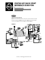
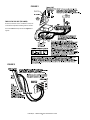
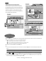
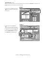
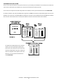
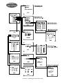
ADDENDUM
Addendum No.:
Date:
C1577M-A
August 4, 2004
Manuals Affected:
CM9760 Series Manuals – C538M, C539M-A, C540M-B, C541M-C, C542M-B, C543M-A,
C544M, C549M-A, C572M, C573M-D, C578M, C579M, C1501M, C1503M, C1510M-QS,
C1510M-A, C1520M-B, C1528M-C, C1940M, C1941M, C1942M, and C1943M
Manual Update:
The CM9760-CC1 has been replaced with the CM9700-CC1 and the CM9760-MGR management software has been replaced with the CM9700-MGR management software.
PRODUCT WARRANTY AND RETURN INFORMATION
Keep the following in mind when referring to the instructions contained in these manuals:
WARRANTY
Pelco will repair or replace, without charge, any merchandise proved defective in material or
workmanship for a period of one year after the date of shipment.
If a warranty repair is required, the Dealer must contact Pelco at (800)þ289-9100 or
(559) 292-1981 to obtain a Repair Authorization number (RA), and provide the following
information:
• The CM9700-CC1 contains the
latest CC1 software (version 9.01 or higher), and is
Exceptions to this warranty are as noted below:
1. Model and serial number
programmed with the new CM9700-MGR
management
software.
2. Date of shipment, P.O.
number, Sales Order
number, or Pelco invoice number
• Five years on FR/FT/FS Series fiber optic products and TW3000 Series unshielded twisted
pair transmission products.
3. Details of the defect or problem
• Three years on Genex® Series products (multiplexers, server, and keyboard).
•
If therenumbers,
is a dispute regarding
the warranty of functions
a product which
does
not fallas
under
Despite the difference in model
the CM9700-CC1
the
same
thethe
warranty conditions stated above, please include a written explanation with the product when
returned.
the
information in these manuals applies to version 9.01 (or
Method
of return shipment shall be the same or equal to the method by which the item was
higher) CPU.
Three years on PMCL200/300/400 Series LCD monitors.
• Three years on Camclosure® and fixed camera models, except the CC3701H-2,
CC3701H-2X, CC3751H-2, CC3651H-2X, MC3651H-2,CM9760-CC1
and MC3651H-2X camera
models, of
and most
which have a five-year warranty.
•
• Two years on standard motorized or fixed focal length lenses.
received by Pelco.
• Two years on Legacy®, CM6700/CM6800/CM9700 Series matrix, and DF5/DF8 Series fixed
RETURNS
• You can add the CM9700-CC1
to an existing CM9760 system if you upgrade the existing
dome products.
In order to expedite parts returned to the factory for repair or credit, please call the factory at
scanners, including units
when used
in
• Two years on Spectra®, Esprit®, ExSite™, and PS20CM9760-CC1
with
continuous motion applications.
289-9100
or (559) 292-1981
to obtainlevel
an authorization
(CA number if returned for
the(800)
current
software
(version
9.01 ornumber
higher).
credit, and RA number if returned for repair).
• Two years on Esprit® and WW5700 Series window wiper (excluding wiper blades).
All merchandise returned for credit may be subject to a 20% restocking and refurbishing
displays.requires
• Two years (except lamp and color wheel) on Digital
Light Processing
(DLP®) 9.01
charge.
Software
version
a minimum of 16 MB of RAM in the CPU. If required, you
The lamp and color wheel will be covered for a period of 90 days. The air filter is not
covered under warranty.
Goods
returned for repair units
or creditusing
should be
clearly
identified with
the assigned
can upgrade the RAM in older
CM9760-CC1
the
software
upgrade
kit CA or RA
number and freight should be prepaid. Ship to the appropriate address below.
• Eighteen months on DX Series digital video recorders, NVR300 Series network video
appropriate
recorders, and Endura™ Series distributed network-based
video products.for your CPU.
If you are located within the continental U.S., Alaska, Hawaii or Puerto Rico, send goods to:
• One year (except video heads) on video cassette recorders (VCRs). Video heads will be
Service Department
covered for a period of six months.
Pelco
•
Do
not
use
the
CM9760-MGR
instructions
contained in these manuals. Refer to the
• Six months on all pan and tilts, scanners or preset lenses used in continuous motion
3500 Pelco Way
applications (that is, preset scan, tour and auto scan modes).
Clovis,
CA
93612-5699
CM9700-MGR Getting Started Software Guide, on-screen help, or Online Help for
Pelco will warrant all replacement parts and repairs for 90 days from the date of Pelco
instructions.
shipment. All goods requiring warranty repair shall be sent freight prepaid to Pelco, Clovis,
California. Repairs made necessary by reason of misuse, alteration, normal wear, or accident
are not covered under this warranty.
Pelco assumes no risk and shall be subject to no liability for damages or loss resulting from
the specific use or application made of the Products. Pelco’s liability for any claim, whether
based on breach of contract, negligence, infringement of any rights of any party or product liability, relating to the Products shall not exceed the price paid by the Dealer to Pelco for such
Products. In no event will Pelco be liable for any special, incidental or consequential damages
(including loss of use, loss of profit and claims of third parties) however caused, whether by
the negligence of Pelco or otherwise.
The above warranty provides the Dealer with specific legal rights. The Dealer may also have
additional rights, which are subject to variation from state to state.
If you are located outside the continental U.S., Alaska, Hawaii or Puerto Rico and are
instructed to return goods to the USA, you may do one of the following:
If the goods are to be sent by a COURIER SERVICE, send the goods to:
Pelco
3500 Pelco Way
Clovis, CA 93612-5699 USA
If the goods are to be sent by a FREIGHT FORWARDER, send the goods to:
Pelco c/o Expeditors
473 Eccles Avenue
South San Francisco, CA 94080 USA
Phone: 650-737-1700
Fax: 650-737-0933
The materials used in the manufacture of this document and its components are compliant to the requirements of Directive 2002/95/EC.
Pelco World Headquarters • 3500 Pelco Way, Clovis, California 93612-5699 USA • www.pelco.com
This equipment contains electrical or electronic components that must be recycled properly to comply with Directive 2002/96/EC of the European Union
USA & Canada: Tel: 800/289-9100 • Fax: 800/289-9150
regarding the disposal of waste electrical and electronic equipment (WEEE). Contact your local dealer for procedures for recycling this equipment.
®
International: Tel: 1-559/292-1981 • Fax: 1-559/348-1120
CM9760-SAT QUICK START
REFERENCE GUIDE FOR:
®
the 9760-SAT physical interface
setup parameters for SAT programming from the 9760-KBD
alarm implementation issues
CONNECT
THE CC1 TO THE SAT (RS-422)
Figure 1 shows a CM9760-SAT connected to a 9760 system. Of particular interest are the COMM
and tie line connections. The COMM connection shown in Figure 1 is the line between port 7
on the CC1 and the COM 2 connection on the SAT. This is detailed in Figure 2.
FIGURE 1
C1510M-QS – CM9760-SAT Quick Start Reference Guide
–1–
FIGURE 2
THE CC1 TO THE SAT (TIE LINES)
Tie lines (a minimum of one, a maximum of four) are
connected in sequential, ascending order to monitorouts on the SAT. Don’t skip around. Use Figure 3 as
a guide.
FIGURE 3
C1510M-QS – CM9760-SAT Quick Start Reference Guide
–2–
SETUP
FIGURE 4
PARAMETERS FOR SAT PROGRAMMING
In order to program and operate the SAT from the 9760-KBD,
some preparatory groundwork must be laid by programming the
following 9760 configuration files: the Comms, Camera and Link
Camera files. Use Figures 4, 5 and 6, respectively, as guides.
These are essentially the only files that need to be programmed
on the 9760 SIDE for basic SAT operation.
FIGURE 5
FIGURE 6
SAT MENU ACCESS
FROM THE 9760-KBD
Programming SAT menus using a KBD200, 300 or 300V is the preferred method (it’s easier and faster); otherwise, the 9760-KBD can be
used. To access the SAT Main menu screen from the 9760-KBD requires that:
the programming files listed in SETUP be configured and loaded
the CC1 is initialized and the COMM link between the CC1 and SAT is active
at least one tie line is physically connected between the SAT and CC1
Next, ensure no one else (9760 SIDE) is using an SAT tie line.
Then:
1. Call up any link camera programmed in the Link Camera file of the MGR (see Figure 6). Use the associated logical number for the
camera.
NOTE: It is not necessary for the Link camera called to actually be connected to the SAT at this time. All that is happening here
is that you, as the operator, are “isolating” a video tie line for the display transfer of the SAT menu to a 9760 monitor.
2. Press the
or the
key, then press the DEF key. If this is the first time accessing that menu, enter the default PIN (1234).
3. Enter 89 in the keypad and press the PRST key (while still in the DEF menu). The main SAT programming menu will appear on the
monitor in front of you. You may now proceed to program the SAT.
C1510M-QS – CM9760-SAT Quick Start Reference Guide
–3–
ALARM IMPLEMENTATION ISSUES
(if needed, reference the attached Default SAT Menu Settings Sheet)
Alarm programming involves configuring SAT Monitor and Alarm
For each destination to be programmed, Pelco recommends that
menus and, possibly, some 9760 System configuration files. If you
you not stray outside the guidelines outlined below for program-
program alarm functions without regard to the status of the
ming the various menus until you are quite familiar with the
monitor-out lines on the SAT, you are going to get into trouble.
ramifications of doing so. Improper programming can lead to
There is only one source of alarms on the SAT: the physical
unexpected (but not uncorrectable) results that might lead you to
actuation of a relay input, going from its non-alarm to its alarm
believe that your equipment isn’t operating properly. This built-in
state. On the other hand, there are three alarm-reporting destina-
alarm reporting flexibility allows for a more versatile, dynamic,
tions possible and each destination is dependent on associated
alarm environment. The trade-off is that you must be observant
programming configurations. In one, the alarm is seen and acted
when configuring the menus.
upon by the LOCAL SAT only. In another, the alarm is seen and
acted upon by the 9760 System only. Finally, the alarm can be seen
and acted upon by both the LOCAL SAT and the 9760 System at
the same time.
SYSTEM ONLY
LOCAL ONLY
For 9760 SIDE alarm viewing and reporting, at least one
For LOCAL SAT alarm viewing and reporting, at least one
monitor-out line on the SAT must be configured as LOCAL and,
connected to it, there should be a physical monitor for viewing
monitor-out line on the SAT must be configured as a TIE LINE and
it should be connected to a video input line on the CM9760-MXB
for viewing purposes.
purposes.
For the monitor-out line just referenced as a tie line, do the
For the monitor connected to the monitor-out line just refer-
following:
enced, do the following:
In the SAT menus
listed below
MONITOR
MENU
ALARM
MENU
➟
➟
➟
➟
➟
➟
➟
In the SAT menus
listed below
Do the following
Set ALM TYPE to AUTO or MAN
MONITOR
MENU
Set VIEW to LOCAL
In the ALARM ENABLE sub-menu:
enable alarms to be viewed
ALARM
MENU
For the alarm inputs desired, choose an
activation TYPE ( N.O. or N.C.)
ARM the alarm in the LOCAL column*
Assign a preset # (PRE) if the alarm
camera is preset capable and you want a
preset called
Make sure the System Alarm columns
➟
➟
➟
➟
➟
➟
➟
Do the following
Set ALM TYPE to OFF
Set VIEW to TIE LINE
In the ALARM ENABLE sub-menu,
disable all alarms
For the alarm inputs desired, choose an
activation TYPE (N.O. or N.C.)
DIS-ARM (- -) all alarms in the LOCAL
ARM column
Zero-out all presets
Enter a physical alarm # (as configured
in the 9760-CC1) in the SYSTEM
ALARMS column. *
are zeroed-out.
* This is the alarm that will be triggered
* Remember, ALM 1 calls SAT camera 1,
on the CM9760-CC1.
ALM 2 calls SAT camera 2, and so on.
➟
C1510M-QS – CM9760-SAT Quick Start Reference Guide
–4–
➟ SYSTEM ONLY
(Continued)
System-only implementation of alarms also requires that configuration files be programmed on the 9760 SIDE of the configuration. In the
Systems Configuration file, specify an Alarm Control Mode of operation.
FIGURE 7
More importantly, in the Comms Configuration file:
➟
Assign alarm monitors for the 9760 operator
to view alarms on.
FIGURE 8
Of equal importance is the CC1 Alarms file:
➟
Fill in the alarm information fields opposite
the physical alarm # that matches the System Alarm
# entered in the contact menu of the SAT Alarms
file (see the SYSTEM ALARMS column reference
under SYSTEM ONLY in the SAT Alarm Menu).
C1510M-QS – CM9760-SAT Quick Start Reference Guide
–5–
COMBINED LOCAL AND SYSTEM
Here, you need to pay close attention to the specific monitor-out line you are setting menu attributes for. For all monitor-outs connected to a
LOCAL monitor, assign Monitor menu attributes just as they were listed and discussed under LOCAL ONLY.
For all monitor-outs configured as a TIE LINE, assign Monitor menu attributes just as they were listed and discussed under SYSTEM ONLY.
The difference between LOCAL ONLY and SYSTEM ONLY as opposed to COMBINED or shared alarm implementation appears when the menu
attributes in the Contact menu of the SAT ALARM file are assigned. It is here that we accommodate both LOCAL and SYSTEM alarm activation
at the same time. This can best be seen in a side-by-side comparison of the menus for the three states of alarm activation.
FIGURE 9
To complete alarm implementation for the combined
example, you must carry through the System Alarm
portion of the menu settings in the same manner that
was done for System Alarm Only. That is, configure the
9760 CC1 configuration menus (System, Comms, and
Alarm files), just as they were listed and discussed
under SYSTEM ONLY.
C1510M-QS – CM9760-SAT Quick Start Reference Guide
–6–
SAT DEFAULT
MENU SETTINGS
C1510M-QS – CM9760-SAT Quick Start Reference Guide
–7–
®
Pelco
3500 Pelco Way
Clovis, CA 93612-5699 USA
In North America and Canada
Tel (800) 289-9100
•
FAX (800) 289-9150
International Customers
Tel +1(559) 292-1981
•
FAX +1(559) 348-1120
www.pelco.com
C1510M-QS – CM9760-SAT Quick Start Reference Guide
–8–