1
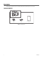
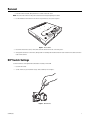
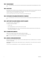
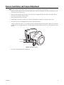
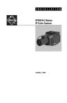
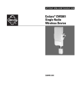
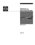
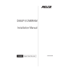
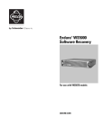
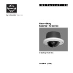
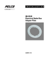
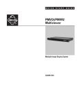
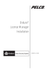
INSTALLATION/OPERATION
PMP-CWV9R
Public View Monitor
Replacement Camera
C2948M (5/08)
2
C2948M (5/08)
Contents
Important Safety Instructions . . . . . . . . . . . . . . . . . . . . . . . . . . . . . . . . . . . . . . . . . . . . . . . . . . . . . . . . . . . . . . . . . . . . . . . . . . . . . . . . . . . . . . . . . . . . 4
Regulatory Notices . . . . . . . . . . . . . . . . . . . . . . . . . . . . . . . . . . . . . . . . . . . . . . . . . . . . . . . . . . . . . . . . . . . . . . . . . . . . . . . . . . . . . . . . . . . . . . . . . . . . 5
Description . . . . . . . . . . . . . . . . . . . . . . . . . . . . . . . . . . . . . . . . . . . . . . . . . . . . . . . . . . . . . . . . . . . . . . . . . . . . . . . . . . . . . . . . . . . . . . . . . . . . . . . . . . 6
Package Contents . . . . . . . . . . . . . . . . . . . . . . . . . . . . . . . . . . . . . . . . . . . . . . . . . . . . . . . . . . . . . . . . . . . . . . . . . . . . . . . . . . . . . . . . . . . . . . . . 6
Removal . . . . . . . . . . . . . . . . . . . . . . . . . . . . . . . . . . . . . . . . . . . . . . . . . . . . . . . . . . . . . . . . . . . . . . . . . . . . . . . . . . . . . . . . . . . . . . . . . . . . . . . . . . . . 7
DIP Switch Settings 7
SW1-1 Video Format . . . . . . . . . . . . . . . . . . . . . . . . . . . . . . . . . . . . . . . . . . . . . . . . . . . . . . . . . . . . . . . . . . . . . . . . . . . . . . . . . . . . . . . . . . . . . . 8
SW1-2 Line Sync . . . . . . . . . . . . . . . . . . . . . . . . . . . . . . . . . . . . . . . . . . . . . . . . . . . . . . . . . . . . . . . . . . . . . . . . . . . . . . . . . . . . . . . . . . . . . . . . . 8
SW1-3 Interlaced Scanning/Progressive Scanning . . . . . . . . . . . . . . . . . . . . . . . . . . . . . . . . . . . . . . . . . . . . . . . . . . . . . . . . . . . . . . . . . . . . . . . 8
SW1-4 Auto White Balance/Manual White Balance . . . . . . . . . . . . . . . . . . . . . . . . . . . . . . . . . . . . . . . . . . . . . . . . . . . . . . . . . . . . . . . . . . . . . 8
SW1-5 Fluorescent/General . . . . . . . . . . . . . . . . . . . . . . . . . . . . . . . . . . . . . . . . . . . . . . . . . . . . . . . . . . . . . . . . . . . . . . . . . . . . . . . . . . . . . . . . 8
SW1-6 General WDR/Maximum WDR . . . . . . . . . . . . . . . . . . . . . . . . . . . . . . . . . . . . . . . . . . . . . . . . . . . . . . . . . . . . . . . . . . . . . . . . . . . . . . . . 8
Camera Installation and Camera Adjustment . . . . . . . . . . . . . . . . . . . . . . . . . . . . . . . . . . . . . . . . . . . . . . . . . . . . . . . . . . . . . . . . . . . . . . . . . . . . . . . 9
Specifications . . . . . . . . . . . . . . . . . . . . . . . . . . . . . . . . . . . . . . . . . . . . . . . . . . . . . . . . . . . . . . . . . . . . . . . . . . . . . . . . . . . . . . . . . . . . . . . . . . . . . . . 10
List of Illustrations
1
2
3
4
C2948M (5/08)
Package Contents . . . . . . . . . . . . . . . . . . . . . . . . . . . . . . . . . . . . . . . . . . . . . . . . . . . . . . . . . . . . . . . . . . . . . . . . . . . . . . . . . . . . . . . . . . . . . . . . . 6
Access Door . . . . . . . . . . . . . . . . . . . . . . . . . . . . . . . . . . . . . . . . . . . . . . . . . . . . . . . . . . . . . . . . . . . . . . . . . . . . . . . . . . . . . . . . . . . . . . . . . . . . . 7
DIP Switches. . . . . . . . . . . . . . . . . . . . . . . . . . . . . . . . . . . . . . . . . . . . . . . . . . . . . . . . . . . . . . . . . . . . . . . . . . . . . . . . . . . . . . . . . . . . . . . . . . . . . 7
Adjusting the Camera . . . . . . . . . . . . . . . . . . . . . . . . . . . . . . . . . . . . . . . . . . . . . . . . . . . . . . . . . . . . . . . . . . . . . . . . . . . . . . . . . . . . . . . . . . . . . . 9
3
Important Safety Instructions
1. Read these instructions.
2. Keep these instructions.
3. Heed all warnings.
4. Follow all instructions.
5. Do not use this apparatus near water.
6. Clean only with dry cloth.
7. Do not block any ventilation openings. Install in accordance with the manufacturer’s instructions.
8. Do not install near any heat sources such as radiators, heat registers, stoves, or other apparatus (including amplifiers) that produce heat.
9. Do not defeat the safety purpose of the polarized or grounding-type plug. A polarized plug has two blades with one blade wider than the
other. A grounding plug has two blades and a third grounding prong. The wide blade or the third prong are provided for your safety. If the
provided plug does not fit into your outlet, consult an electrician for replacement of the obsolete outlet.
10. Protect the power cord from being walked on or pinched particularly at plugs, convenience receptacles, and the points where they exit from
the apparatus.
11. Only use attachments/accessories specified by the manufacturer.
12. Only use with the cart, stand, tripod, bracket, or table specified by the manufacturer, or sold with the apparatus. When a cart is used, use
caution when moving the cart/apparatus combination to avoid injury from tip-over.
13. Refer all servicing to qualified service personnel. Servicing is required when the apparatus has been damaged in any way, such as powersupply cord or plug is damaged, liquid has been spilled or objects have fallen into the apparatus, the apparatus has been exposed to rain or
moisture, does not operate normally, or has been dropped.
14. Unplug the apparatus during lightning storms or when unused for long periods of time.
15. Apparatus shall not be exposed to dripping or splashing and no objects filled with liquids, such as vases shall be placed on the apparatus.
16. WARNING: To reduce the risk of fire or electric shock, do not expose this apparatus to rain or moisture.
17. Installation should be done only by qualified personnel and conform to all local codes.
18. Unless this unit is specifically marked as NEMA Type 3, 3R, 3S, 4, 4X, 6, or 6P enclosure, it is designed for indoor use only and it must not
be installed where exposed to rain and moisture.
19. Only use installation methods and materials capable of supporting four times the maximum specified load.
20. Only use replacement parts recommended by Pelco.
21. Avoid touching the screen directly with your fingers as the oils from your skin may be difficult to remove from the LCD.
22. Do not apply direct pressure on the screen.
23. Keep the monitor in a dust-free environment and away from strong electromagnetic fields.
24. Do not use attachments, such as mounts, that are not recommended by Pelco. They may be hazardous.
25. Do not place the monitor on an unstable stand, bracket, or mount. The unit may fall, causing serious damage to the unit or injury to a
person. Only use mounts recommended by Pelco.
26. A CCC-approved power cord must be used to power this equipment when used in China.
27. A still image displayed too long may cause permanent damage to the LCD panel. Watching the LCD in 4:3 format for a long time may leave
traces of borders displayed on the left, right and center of the screen caused by the difference of light emission on the screen. Using a
camera or a system may cause a similar effect to the screen. Damages caused by this effect are not covered by the warranty.
The product and/or manual may bear the following marks:
This symbol indicates that dangerous voltage constituting a risk of electric shock is present
within this unit.
This symbol indicates that there are important operating and maintenance instructions in
the literature accompanying this unit
4
CAUTION:
RISK OF ELECTRIC SHOCK.
DO NOT OPEN.
C2948M (5/08)
Regulatory Notices
This device complies with Part 15 of the FCC Rules. Operation is subject to the following two conditions: (1) this device may not cause harmful
interference, and (2) this device must accept any interference received, including interference that may cause undesired operation.
RADIO AND TELEVISION INTERFERENCE
This equipment has been tested and found to comply with the limits of a Class A digital device, pursuant to Part 15 of the FCC Rules. These limits
are designed to provide reasonable protection against harmful interference when the equipment is operated in a commercial environment. This
equipment generates, uses, and can radiate radio frequency energy and, if not installed and used in accordance with the instruction manual, may
cause harmful interference to radio communications. Operation of this equipment in a residential area is likely to cause harmful interference in
which case the user will be required to correct the interference at his own expense.
Changes and Modifications not expressly approved by the manufacturer or registrant of this equipment can void your authority to operate this
equipment under Federal Communications Commission’s rules.
In order to maintain compliance with FCC regulations shielded cables must be used with this equipment. Operation with non-approved
equipment or unshielded cables is likely to result in interference to radio and television reception.
This Class A digital apparatus complies with Canadian ICES-003.
Cet appareil numérique de la classe A est conforme à la norme NMB-003 du Canada.
C2948M (5/08)
5
Description
The PMP CWV9R is the replacement camera for the PMP20B, PMP20W, PMP26B, and PMP26W public view monitors (PVMs).
PACKAGE CONTENTS
CAMERA
SCREWS
3 EA.
SPACERS
3 EA.
INSTALLATION MANUAL
1 EA.
Figure 1. Package Contents
6
C2948M (5/08)
Removal
1. Place the monitor face down, being careful not to scratch or touch the screen.
NOTE: Disconnect the monitor from the power source before removing and replacing the camera.
2. Use the thumbscrew on the bottom of the monitor to open the access door, refer to Figure 2.
Figure 2. Access Door
3. Unscrew the three metric screws (14 mm) that secure the camera. Remove the screws and spacers.
4. Gently pull the camera out of the monitor, being careful not to damage the attached connection leads. Detach the two camera connection
leads from the camera
DIP Switch Settings
Set the DIP switches on the replacement camera before installing it in the PVM.
1. Locate the DIP switch.
2. Set the switches for your installation using a small screwdriver, refer to Figure 3.
Figure 3. DIP Switches
C2948M (5/08)
7
SW1-1 VIDEO FORMAT
SW1-1 is controlled through the on-screen menu. Refer to the Public View Monitor Installation/Operation manual (C2943M) that came with the
unit.
SW1-2 LINE SYNC
When multiple cameras are connected to the same switching device, vertical roll can occur on the monitor. AC line lock eliminates vertical roll by
locking the frame rate to the power supply frequency. Each camera output is synchronized to the power supply frequency.
Internal line sync disables line lock and synchronizes cameras internally.
Set SW1-2 to OFF to use AC line lock. Set it to ON to use internal line sync. The default setting is OFF.
SW1-3 INTERLACED SCANNING/PROGRESSIVE SCANNING
SW1-3 is controlled through the on-screen menu. Refer to the Public View Monitor Installation/Operation manual (C2943M) that came with the
unit.
SW1-4 AUTO WHITE BALANCE/MANUAL WHITE BALANCE
Auto white balance (AWB) is enabled by default (OFF).
To manually set and lock the white balance:
1. Set SW1-4 to ON.
2. Hold a white background in front of the lens until the video shows all white.
3. While holding the background in place, set SW1-4 to OFF. A green block and a white block alternate briefly on the video image until the
manual white balance (MWB) process is complete.
SW1-5 FLUORESCENT/GENERAL
Enable this option to adjust the camera for the best operation under fluorescent lighting.
Set SW1-5 to OFF for fluorescent lighting. Set it to ON for general lighting. The default setting is ON.
NOTE: If you use fluorescent operation, you should use AC line lock for best results.
SW1-6 GENERAL WDR/MAXIMUM WDR
Maximum wide dynamic range (WDR) supports approximately 36 dB of additional dynamic range over a standard camera. Use it for installations
that require the maximum WDR.
General WDR supports approximately 20 dB of additional dynamic range over a standard camera. Use it for installations that do not require the
maximum WDR.
Set SW1-6 to ON to select maximum WDR. Set it to OFF to select general WDR. The default setting is ON.
8
C2948M (5/08)
Camera Installation and Camera Adjustment
NOTE: When installing the camera, always touch the metal on the chassis first to avoid static electricity damage.
1. Plug the two camera connection leads from inside the monitor into the connectors on the camera. (The connectors are different sizes and
will only connect in the correct position.)
2. Attach the camera using three spacers and three screws (14 mm). Do not overtighten the screws or the spacers will collapse. The focus
knobs need to be positioned as shown in Figure 4.
3. Tuck the camera leads neatly into the monitor.
4. Verify the video on the monitor. If satisfactory, close the door and hand-tighten the thumbscrew. If unsatisfactory, go to step 5.
5. The camera focus and zoom can be adjusted on the camera located inside the monitor.
To adjust the camera zoom and focus, first loosen the zoom and focus knobs by turning them counterclockwise. Adjust the zoom and focus
by sliding the knobs in the appropriate direction. Then lightly tighten the knobs by turning them clockwise to lock the adjustments (refer to
Figure 4).
FOCUS KNOB
ZOOM KNOB
Figure 4. Adjusting the Camera
6. Close the door and hand-tighten the door thumbscrew.
C2948M (5/08)
9
Specifications
MODELS
PMP-CWV9R
WDR replacement camera for the PMP20B, PMP20W, PMP26B, and PMP26W public view monitors
CAMERA SPECIFICATIONS
Imaging Device
Picture Elements
Dynamic Range
Scanning System
Horizontal Resolution
NTSC
PAL
Signal-to-Noise Ratio
Minimum Illumination
Color (Day)
SENS 8X
Gain Control
Exposure
White Balance
Background Compensation
Sync Format
1/3-inch pixel-based imager
720 (H) x 540 (V)
102 dB typical, 120 dB maximum
2:1 interlace/progressive
504 TV lines
504 TV lines
>53 dB
0.8 lux
0.2 lux
Auto (36 dB maximum)
Auto (1/15 to 1/22,000)
Auto or manual, 2800°K to 7500°K
Auto
NTSC/PAL
LENS SPECIFICATIONS
Focal Length
Format Size
F-Number
Operation
Iris
Focus
Zoom
Angle of View*
Horizontal
Diagonal
Vertical
3.0 mm to 9.0 mm
1/3-inch
f/1.5 to 3.0
Auto
Manual
Manual
32.4° to 13.6°
41.4° to 17.2°
23.8° to 10.2°
*Focal length specifications presume a 10% horizontal and 4% vertical monitor overscan.
(Design and product specifications subject to change without notice.)
10
C2948M (5/08)
PRODUCT WARRANTY AND RETURN INFORMATION
WARRANTY
Pelco will repair or replace, without charge, any merchandise proved defective in
material or workmanship for a period of one year after the date of shipment.
Exceptions to this warranty are as noted below:
• Five years on fiber optic products and TW3000 Series unshielded twisted pair
(UTP) transmission products.
• Three years on Spectra® IV products.
• Three years on Genex® Series products (multiplexers, server, and keyboard).
• Three years on DX Series digital video recorders, DVR5100 Series digital video
recorders, DigitalSENTRY® Series hardware products, DVX Series digital video
recorders, NVR300 Series network video recorders, and Endura ® Series
distributed network-based video products.
• Three years on Camclosure® and Pelco-branded fixed camera models, except
the CC3701H-2, CC3701H-2X, CC3751H-2, CC3651H-2X, MC3651H-2, and
MC3651H-2X camera models, which have a five-year warranty.
• Three years on PMCL200/300/400 Series LCD monitors.
• Two years on standard motorized or fixed focal length lenses.
• Two years on Legacy®, CM6700/CM6800/CM9700 Series matrix, and DF5/DF8
Series fixed dome products.
• Two years on Spectra III™, Spectra Mini, Esprit®, ExSite®, and PS20 scanners,
including when used in continuous motion applications.
• Two years on Esprit and WW5700 Series window wiper (excluding wiper
blades).
• Two years (except lamp and color wheel) on Digital Light Processing (DLP®)
displays. The lamp and color wheel will be covered for a period of 90 days. The
air filter is not covered under warranty.
• Two years on Intelli-M® eIDC controllers.
• One year (except video heads) on video cassette recorders (VCRs). Video heads
will be covered for a period of six months.
• Six months on all pan and tilts, scanners, or preset lenses used in continuous
motion applications (preset scan, tour, and auto scan modes).
Pelco will warrant all replacement parts and repairs for 90 days from the date of
Pelco shipment. All goods requiring warranty repair shall be sent freight prepaid
to a Pelco designated location. Repairs made necessary by reason of misuse,
alteration, normal wear, or accident are not covered under this warranty.
Pelco assumes no risk and shall be subject to no liability for damages or loss
resulting from the specific use or application made of the Products. Pelco’s liability
for any claim, whether based on breach of contract, negligence, infringement of
any rights of any party or product liability, relating to the Products shall not exceed
the price paid by the Dealer to Pelco for such Products. In no event will Pelco be
liable for any special, incidental, or consequential damages (including loss of use,
loss of profit, and claims of third parties) however caused, whether by the
negligence of Pelco or otherwise.
The above warranty provides the Dealer with specific legal rights. The Dealer may
also have additional rights, which are subject to variation from state to state.
If a warranty repair is required, the Dealer must contact Pelco at (800) 289-9100 or
(559) 292-1981 to obtain a Repair Authorization number (RA), and provide the
following information:
1. Model and serial number
2. Date of shipment, P.O. number, sales order number, or Pelco invoice number
3. Details of the defect or problem
If there is a dispute regarding the warranty of a product that does not fall under
the warranty conditions stated above, please include a written explanation with
the product when returned.
Method of return shipment shall be the same or equal to the method by which the
item was received by Pelco.
RETURNS
To expedite parts returned for repair or credit, please call Pelco at (800) 289-9100
or (559) 292-1981 to obtain an authorization number (CA number if returned for
credit, and RA number if returned for repair) and designated return location.
All merchandise returned for credit may be subject to a 20 percent restocking and
refurbishing charge.
Goods returned for repair or credit should be clearly identified with the assigned
CA or RA number and freight should be prepaid.
1-8-08
The materials used in the manufacture of this document and its components are compliant to the requirements of Directive 2002/95/EC.
This equipment contains electrical or electronic components that must be recycled properly to comply with Directive 2002/96/EC of the European Union
regarding the disposal of waste electrical and electronic equipment (WEEE). Contact your local dealer for procedures for recycling this equipment.
REVISION HISTORY
Manual #
C2948M
Date
5/08
Comments
Original version.
Pelco and the Pelco logo are registered trademarks of Pelco, Inc.
© Copyright 2008, Pelco, Inc. All rights reserved.
Worldwide Headquarters
3500 Pelco Way
Clovis, California 93612 USA
USA & Canada
Tel: 800/289-9100
Fax: 800/289-9150
International
Tel: 1-559/292-1981
Fax: 1-559/348-1120
www.pelco.com
ISO9001
Australia
| Finland | France | Germany | Italy | Macau | The Netherlands | Russia | Singapore
| Spain | Sweden | United Arab Emirates | United Kingdom | United States
South Africa