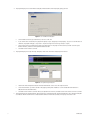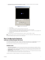
1
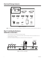
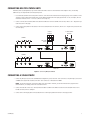
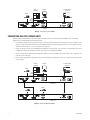
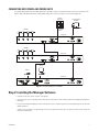
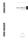
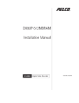
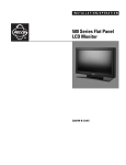
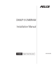
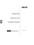
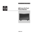
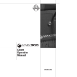
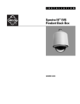
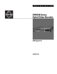
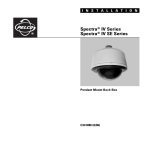
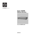
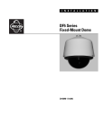
Q U I C K
S T A R T
G U I D E
PMVC4/PMVR2
Multiviewer
Multiple Image Display System
C2929M (5/06)
Illustrated Package Contents
- OR PARTS BOX
PMVC4 MULTIVIEWER
DVI CABLE
10” (25.4 cm)
DB9 CABLE
(LOOPING)
SCREWS (8)
6’ (1.8 m)
DB9 CABLE
(TO PC)
RACK MOUNT EARS
PMVR2 MULTIVIEWER
USA STANDARD
POWER CORD
(110 VAC)
EUROPEAN
STANDARD POWER
CORD (220VAC)
QUICK START
GUIDE
INSTALLATION CD
RS-232 TO RS-485
CONVERTER
Figure 1. Package Contents
NOTE: For detailed information on the installation, configuration, and operation of the multiviewers, consult the manual on the installation CD.
Step 1: Installing the Hardware
CONNECTING A SINGLE PMVC4
1. Connect the cameras to the video BNC inputs on the back of the PMVC4.
2. Connect the male end of the 6-foot (1.8-meter) DB9 serial cable to COM IN on the PMVC4. Connect the other end (with the RS-232-toRS-485 converter) to the PC’s COM port.
3. Connect either a DVI cable from Cascade/DVI Out or a VGA cable from VGA Out to the display monitor.
DISPLAY
MONITOR
PC AND CONTROL
MONITOR
CAMERAS
VGA OR DVI
OUTPUT
Video 1
Video 2
Video 3
VGA Out
Video 4
COM IN
012
EF
8
6 7 9A
345
BCD
Cascade In
Cascade/DVI Out
Unit ID
COM OUT
100-240 VAC
PMVC4
Figure 2. Connecting a Single PMVC4
2
C2929M (5/06)
CONNECTING MULTIPLE PMVC4 UNITS
Remember, when cascading PMVC4s, loop from the multiviewer with a lower ID to the multiviewer with a higher ID. Also, the following
additional steps are required when connecting multiple units.
1. Use a flat head screwdriver on the rotary Unit ID switch to set the ID of the first multiviewer in the display group to 0. This identifies it in the
software as the first multiviewer. Change the ID of every additional multiviewer in the group by increments of one; for example, the next
multiviewer will have an ID of 1. Do not use F, which is for testing only.
2. Connect a 10-inch (25.4-centimeter) DB9 serial cable from COM OUT on unit 0 to COM IN on the next unit, which is unit 1. Repeat until you
reach the last unit in the group.
3. Connect a DVI looping cable from Cascade/In on unit 0 to Cascade/DVI Out on the next unit, which is unit 1. Repeat until you reach the last
unit in the group.
DISPLAY
MONITOR
PC AND CONTROL
MONITOR
CAMERAS
VGA OR DVI
OUTPUT
Video 1
Video 2
Video 3
VGA Out
Video 4
COM IN
012
EF
8
6 7 9A
345
BCD
Cascade In
Unit ID
Cascade/DVI Out
COM OUT
100-240 VAC
PMVC4 ID0
CAMERAS
Video 1
Video 2
Video 3
VGA Out
Video 4
COM IN
012
EF
8
6 7 9A
345
BCD
Cascade In
Unit ID
Cascade/DVI Out
COM OUT
100-240 VAC
PMVC4 ID1
Figure 3. Connecting Multiple PMVC4s
CONNECTING A SINGLE PMVR2
1. Connect any DVI inputs (such as from a VMX300 video management system) to the DVI 1 and 2 connectors or any VGA inputs (such as from
a DX8000 series digital video recorder) to the VGA 1 and 2 connectors on the back of the PMVR2.
NOTE: You can have either DVI or VGA, but not both on the same channel. However, you can have DVI and VGA if you put them on
different channels; for example, DVI on DVI 1 and VGA on VGA 2.
2. Connect the male end of the 6-foot (1.8-meter) DB9 serial cable to COM IN on the PMVC4. Connect the other end (with the RS-232-toRS-485 converter) to the PC’s COM port.
3. Connect either a DVI looping cable from Cascade/DVI Out or a VGA looping cable from VGA Out to the display monitor.
C2929M (5/06)
3
DISPLAY
MONITOR
PC AND CONTROL
MONITOR
VMX300
DX8000
VGA
OR DVI
OUTPUT
VGA 1
DVI 1
DVI 2
VGA 2
ON
OFF
COM IN
01 2
EF
89
67 A
345
BCD
Cascade In
VGA Out
Cascade/DVI Out
Unit ID
COM OUT
100-240 VAC
PMVR2
Figure 4. Connecting a Single PMVR2
CONNECTING MULTIPLE PMVR2 UNITS
Remember, when cascading PMVR2s, loop from the multiviewer with a lower ID to the multiviewer with a higher ID. Also, the following
additional steps are required when connecting multiple units.
1. Use a flat head screwdriver on the rotary Unit ID switch to set the ID of the first multiviewer in the display group to 0. This identifies it in the
software as the first multiviewer. Change the ID of every additional multiviewer in the group by increments of one; for example, the next
multiviewer will have an ID of 1. Do not use F, which is for testing only.
2. Connect any DVI inputs (such as from a VMX300 video management system) to the DVI 1 and 2 connectors or any VGA inputs (such as from
a DX8000 series digital video recorder) to the VGA 1 and 2 connectors on the back of the PMVR2.
3. Connect a 10-inch (25.4-centimeter) DB9 serial cable from COM OUT on unit 0 to COM IN on the next unit, which is unit 1. Repeat until you
reach the last unit in the group.
4. Connect a DVI looping cable from Cascade/In on unit 0 to Cascade/DVI Out on the next unit, which is unit 1. Repeat until you reach the last
unit in the group.
DISPLAY
MONITOR
PC AND CONTROL
MONITOR
VMX300
DX8000
VGA
OR DVI
OUTPUT
VGA 1
DVI 1
DVI 2
VGA 2
COM IN
01 2
EF
89
67 A
345
BCD
Cascade In
Unit ID
VGA Out
Cascade/DVI Out
COM OUT
100-240 VAC
PMVR2 ID0
DX8000
DX8000
VGA 1
DVI 1
DVI 2
VGA 2
COM IN
01 2
EF
89
67 A
345
BCD
Cascade In
Cascade/DVI Out
Unit ID
VGA Out
COM OUT
100-240 VAC
PMVR2 ID1
Figure 5. Connecting Multiple PMVR2s
4
C2929M (5/06)
CONNECTING BOTH PMVC4 AND PMVR2 UNITS
In cascading PMVC4 multiviewers with PMVR2 multiviewers, remember to loop from a multiviewer with the lower ID to a multiviewer with a
higher ID. Begin with PMVC4 multiviewers and then PMVR2 multiviewers. Follow the instructions for connecting multiple units.
DISPLAY
MONITOR
PC AND CONTROL
MONITOR
VGA OR DVI
OUTPUT
CAMERAS
PMVC4 ID0
Video 1
Video 2
Video 3
VGA Out
Video 4
COM IN
012
EF
8
6 7 9A
345
BCD
Cascade In
Unit ID
Cascade/DVI Out
COM OUT
100-240 VAC
CAMERAS
PMVC4 ID1
Video 1
Video 2
Video 3
VGA Out
Video 4
COM IN
012
EF
8
6 7 9A
345
BCD
Cascade In
Unit ID
Cascade/DVI Out
COM OUT
100-240 VAC
VMX300
DX8000
PMVR2 ID2
VGA 1
DVI 1
DVI 2
VGA 2
COM IN
01 2
EF
89
67 A
345
BCD
Cascade In
Cascade/DVI Out
VGA Out
Unit ID
COM OUT
100-240 VAC
Figure 6. Connecting PMVC4s and a PMVR2
Step 2: Installing the Manager Software
1. Insert the resource CD in your PC. A splash screen appears.
2. Click in the splash screen. The program will be extracted into a folder, and a shortcut called Pelco Multiviewer Manager will be added to
the desktop.
3. Locate the Pelco Multiviewer Manager shortcut on the desktop. Click it to launch the application. The program displays the Scan All Online
Modules dialog box.
Click Next. If the software does not find anything, it will not let you go further. Click Rescan in this situation to make sure the software can
detect all your multiviewers.
C2929M (5/06)
5
4. The program displays the Set Total Monitor dialog box, which determines how many display groups you have.
Figure 7. Set Total Monitor Dialog Box
•
•
•
•
Set the number of monitors (up to 50 monitors). You must set this first.
If you click the Auto Set check box, the program will quickly set up a single group or multiple groups. (If you do not click the Auto Set
check box, the program will bypass steps 6 and 7. Skip the following instructions and go directly to Step 8.)
Choose either to have one multiviewer per group or all multiviewers in one group. Pick the resolution you want. Select the space
between windows, and then click the Open MCC Label check box.
Click Back to return or Next to continue.
5. The program displays the Set Up All Groups dialog box, which shows the monitor and group for that monitor.
Figure 8. Set Up All Groups Dialog Box
•
•
Leave the No VGA Overlay box checked in the Attach VGA Monitor section. Select the output resolution.
Select the multiviewers you want to include in the group by clicking their checkboxes. Use the Include and Remove buttons to
add/remove the desired multiviewers.
•
Click Back to return or Next to continue. When you complete the last monitor, click Back to return to the monitor or Finish to continue.
6. The program displays the Report dialog box, which confirms the selected multiviewers and their identifications (IDs). The Report dialog box
also indicates whether a VGA monitor is attached and the number of multiviewers (modules) in the group. Click Cancel or OK.
6
C2929M (5/06)
7. The program next displays the Set Monitor Type dialog box. The settings in this dialog box are optional. They are only a graphic
representation of the system and do not actually affect the system itself.
Figure 9. Set Monitor Type Dialog Box
•
•
•
•
Select the group.
Use the zoom buttons to decrease or increase the image on the control screen.
Select values for ratio and size. Click the Apply All check box to apply the ratio settings to all the images.
Use the horizontal and vertical menus to quickly organize multiple group display icons. This feature lets you set up a global view of
your system to see where each group display is located. Click the SET button.
•
Click Cancel or OK.
8. The program displays the Pelco Monitor Manager window (refer to Figure 10). Software installation is complete.
NOTE: If you need to modify some of the settings after the initial installation, you must exit the program, access Windows Explorer, locate the
Pelco Multiviewer Manager program file, delete the Save file, and begin again.
Step 3: Configuring the Equipment
PELCO MULTIVIEWER MANAGER SOFTWARE
The Pelco Multiviewer Manager (PMM) software is required to configure and control the multiviewers. This included program gives you access
to system level commands, group level commands, and window level commands through the Pelco Monitor Manager window.
Use the pull-down menu to select between system level (overview) or group level control.
COMMAND AREAS
•
System Level and Group Level: These menus (File, Program, and Tools) display system level and group level commands. System level
commands are program features that make system-wide changes. Group level commands affect only the group currently being controlled.
•
Group Level Only: These menus only display group level commands. Access these by right-clicking the mouse while the cursor is in the
black background area, outside a video window.
•
Window Level Only: These menus only display commands at the video window level. Access these by right-clicking the mouse while the
cursor is in a video window. Window level commands affect the selected video window only.
For detailed information on configuring the equipment, refer to the manual on the included resource CD.
C2929M (5/06)
7
PRODUCT WARRANTY AND RETURN INFORMATION
WARRANTY
Pelco will repair or replace, without charge, any merchandise proved defective in material or
workmanship for a period of one year after the date of shipment.
Exceptions to this warranty are as noted below:
• Five years on FR/FT/FS Series fiber optic products and TW3000 Series unshielded twisted
pair transmission products.
• Three years on Genex ® Series products (multiplexers, server, and keyboard).
• Three years on Camclosure ® and fixed camera models, except the CC3701H-2,
CC3701H-2X, CC3751H-2, CC3651H-2X, MC3651H-2, and MC3651H-2X camera models,
which have a five-year warranty.
• Three years on PMCL200/300/400 Series LCD monitors.
• Two years on standard motorized or fixed focal length lenses.
• Two years on Legacy ®, CM6700/CM6800/CM9700 Series matrix, and DF5/DF8 Series
fixed dome products.
®
®
™
• Two years on Spectra , Esprit , ExSite , and PS20 scanners, including when used in
continuous motion applications.
• Two years on Esprit ® and WW5700 Series window wiper (excluding wiper blades).
• Two years (except lamp and color wheel) on Digital Light Processing (DLP ®) displays.
The lamp and color wheel will be covered for a period of 90 days. The air filter is not
covered under warranty.
• Eighteen months on DX Series digital video recorders, NVR300 Series network video
recorders, and Endura ™ Series distributed network-based video products.
• One year (except video heads) on video cassette recorders (VCRs). Video heads will be
covered for a period of six months.
• Six months on all pan and tilts, scanners or preset lenses used in continuous motion
applications (that is, preset scan, tour and auto scan modes).
Pelco will warrant all replacement parts and repairs for 90 days from the date of Pelco
shipment. All goods requiring warranty repair shall be sent freight prepaid to Pelco, Clovis,
California. Repairs made necessary by reason of misuse, alteration, normal wear, or accident
are not covered under this warranty.
Pelco assumes no risk and shall be subject to no liability for damages or loss resulting from
the specific use or application made of the Products. Pelco’s liability for any claim, whether
based on breach of contract, negligence, infringement of any rights of any party or product
liability, relating to the Products shall not exceed the price paid by the Dealer to Pelco for
such Products. In no event will Pelco be liable for any special, incidental or consequential
damages (including loss of use, loss of profit and claims of third parties) however caused,
whether by the negligence of Pelco or otherwise.
The above warranty provides the Dealer with specific legal rights. The Dealer may also have
additional rights, which are subject to variation from state to state.
If a warranty repair is required, the Dealer must contact Pelco at (800) 289-9100 or
(559) 292-1981 to obtain a Repair Authorization number (RA), and provide the following
information:
1. Model and serial number
2. Date of shipment, P.O. number, Sales Order number, or Pelco invoice number
3. Details of the defect or problem
If there is a dispute regarding the warranty of a product which does not fall under the
warranty conditions stated above, please include a written explanation with the product
when returned.
Method of return shipment shall be the same or equal to the method by which the item was
received by Pelco.
RETURNS
In order to expedite parts returned to the factory for repair or credit, please call the factory at
(800) 289-9100 or (559) 292-1981 to obtain an authorization number (CA number if returned
for credit, and RA number if returned for repair).
All merchandise returned for credit may be subject to a 20% restocking and refurbishing
charge.
Goods returned for repair or credit should be clearly identified with the assigned CA or RA
number and freight should be prepaid. Ship to the appropriate address below.
If you are located within the continental U.S., Alaska, Hawaii or Puerto Rico, send goods to:
Service Department
Pelco
3500 Pelco Way
Clovis, CA 93612-5699
If you are located outside the continental U.S., Alaska, Hawaii or Puerto Rico and are
instructed to return goods to the USA, you may do one of the following:
If the goods are to be sent by a COURIER SERVICE, send the goods to:
Pelco
3500 Pelco Way
Clovis, CA 93612-5699 USA
If the goods are to be sent by a FREIGHT FORWARDER, send the goods to:
Pelco c/o Expeditors
473 Eccles Avenue
South San Francisco, CA 94080 USA
Phone: 650-737-1700
Fax: 650-737-0933
The materials used in the manufacture of this document and its components are compliant to the requirements of Directive 2002/95/EC.
This equipment contains electrical or electronic components that must be recycled properly to comply with Directive 2002/96/EC of the European Union
regarding the disposal of waste electrical and electronic equipment (WEEE). Contact your local dealer for procedures for recycling this equipment.
REVISION HISTORY
Manual #
C2929M
Date
5/06
Comments
Original version.
Pelco, the Pelco logo, Camclosure, Esprit, Genex, Legacy, and Spectra are registered trademarks of Pelco.
Endura and ExSite are trademarks of Pelco.
DLP is a registered trademark of Texas Instruments, Inc.
©Copyright 2006, Pelco. All rights reserved.
Worldwide Headquarters • 3500 Pelco Way • Clovis, California 93612 USA • www.pelco.com
USA & Canada • Tel: 800/289-9100 • Fax: 800/289-9150
International • Tel: 1-559/292-1981 • Fax: 1-559/348-1120