1
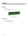
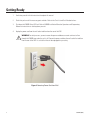
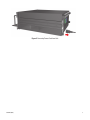
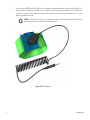
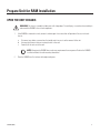
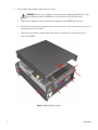
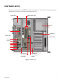
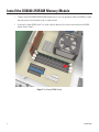
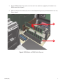
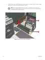
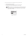
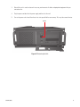
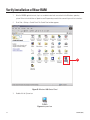
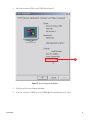
DX8000-256RAM
Installation Manual
DX8000 Digital Video Recorder
C1602M (6/04)
Protecting people and property in a million locations worldwide.
Introduction
The following instructions serve as a guide for the installation of the DX8000-256RAM memory expansion module.
PARTS LIST
Qty Description
1
256 MB double data rate (DDR) dual inline memory module (DIMM)
1
Adhesive-backed upgrade part label
Figure 1. 256 MB DIMM Module
TOOLS NEEDED
1
1
4
C1602M (6/04)
Phillips-head screwdriver #1 (nonmagnetic)
Properly grounded ESD wrist strap and mat
Small containers for storing screws (optional)
1
Getting Ready
1.
Familiarize yourself with the instructions throughout this manual.
2.
Check that you have all the necessary parts and tools. Refer to the Parts List and Tools Needed sections.
3.
Shut down the DX8000 Series DVR unit. Refer to DX8000 Installation Manual or Operations and Programming
Manual for instructions on shutting down your unit.
4.
Unplug the power cord from the wall socket and then from the rear of the DVR.
WARNING: For safety reasons, you must remove the power cord because current continues to flow
through the DX8000 even when the unit is off. Remove the power cord from the wall socket first and then
from the rear of the DVR. It is critical that the unit be unplugged for your safety.
Figure 2. Removing Power Cord from Wall
2
C1602M (6/04)
Figure 3. Removing Power Cord from Unit
C1602M (6/04)
3
5.
Ensure that the DX8000 Series DVR and all of its components are protected against electrostatic discharge (ESD).
Before handling any electronic components, you should take steps to ground yourself properly so that any built-up
static electric charges are dissipated away from the unit. The most effective method for combating ESD is to use a
properly grounded wrist strap.
NOTE: If you do not have access to a grounded wrist strap, you can discharge any built-up static by
periodically touching an unpainted section of the chassis.
Figure 4. ESD Protection
4
C1602M (6/04)
Prepare Unit for RAM Installation
OPEN THE UNIT CHASSIS
WARNING: The chassis assembly includes parts with sharp edges. To avoid injury, use caution when working in
and around the DX8000’s chassis and components.
1.
If the DX8000 is mounted in a rack, remove it and transport it to an area that will provide full access to the unit
chassis:
a.
b.
c.
Disconnect any cables or connections that might restrict access to or the removal of the unit.
Unscrew the fasteners that are securing the unit in the rack.
Carefully lift the unit out of the rack.
NOTE: Removing the DX8000 from a rack may require more than one person. Refer to the DX8000
Installation Manual for rack mounting information.
2.
C1602M (6/04)
Place the DX8000 on a flat surface with ample workspace.
5
3.
Using a Phillips-head screwdriver, remove the chassis cover:
WARNING: Make sure unit is turned off and you are wearing a properly grounded ESD wrist strap
before attempting to open the DX8000 chassis cover. Refer to the Getting Ready section.
a.
Remove the two top-most screws on the left and right side panels of the DX8000. Refer to Figure 5.
b.
Remove the four silver screws fastening the cover to the rear of the unit. These screws are the ones closest to
the top of the unit. Refer to Figure 5.
c.
Carefully remove the chassis cover by sliding it back and up. Set aside the cover. Figure 6 illustrates the
interior of the DX8000.
Figure 5. Removing Chassis Cover
6
C1602M (6/04)
COMPONENT LAYOUT
Figure 6 shows the location of your DX8000 Series DVR’s major components. Certain cables and components have been
omitted from the illustrations in this manual for the purpose of clarity.
DIMM SOCKETS (RAM)
POWER SUPPLY
CD-RW
CPU
HARD DRIVE
REAR OF DVR
FRONT OF DVR
VGA CARD
PCI SLOT 1
2
3
4
5
6
REAR CROSS-BRACE
MOTHERBOARD
IDE CONNECTORS
(SECONDARY)
FRONT CROSS-BRACE
MOTHERBOARD
IDE CONNECTORS
PRIMARY
Figure 6. DX8000 Interior
C1602M (6/04)
7
Install the DX8000-256RAM Memory Module
1.
Carefully remove the DX8000-256RAM DIMM module from its static-safe packaging. Handle the DIMM by its edges
and avoid contact with the module’s chips or conductive leads.
2.
Locate the first empty DIMM socket. This socket is directly adjacent to the socket containing the existing DIMM
module. Refer to Figure 7.
Figure 7. First Empty DIMM Socket
8
C1602M (6/04)
3.
Align the DIMM module with the socket so that the notch in the module lines up properly with the break in the
DIMM socket. Refer to Figure 8.
4.
Make sure that the white retaining clips are not in the locked position by pressing outward and down on each clip.
Refer to Figure 8.
3
4
Figure 8. DIMM Module and DIMM Socket Alignment
C1602M (6/04)
9
5.
Carefully, but firmly, push the DIMM module into the empty socket until it is properly seated. The module is properly
seated when the retaining clips snap back into place as in Figure 9.
NOTE: When inserting the DIMM module into the socket, use enough pressure to ensure that the
retaining clips snap back into place. Be careful, however, not to use excessive force that might damage
the DIMM module or surrounding components.
5
5
Figure 9. Seating and Securing the DIMM Module
10
C1602M (6/04)
Reassemble the Unit
1.
Replace the chassis cover using the same screws you removed from the side and rear of the unit. Refer to Figure 10.
Figure 10. Replacing Chassis Cover
C1602M (6/04)
11
2.
Attach the silver part label that came in your upgrade kit to the inside of your DVR’s front door.
a.
b.
c.
Remove the paper backing from the part label.
Carefully place the label, adhesive-side down, on a free section of the inside of the door.
Press down firmly to ensure that the label properly adheres to the inside of the door.
NOTE: In the event that your unit or its components require service, part labels must be present and
appropriately affixed to the unit’s door. Pelco product support personnel use these labels to identify
the exact components installed in your system. A separate part label is required for each upgrade
component installed on the DX8000.
DX8000-256RAM
04070-FDF-C6B6
Figure 11. Product Label
12
C1602M (6/04)
3.
Reinstall the unit in a rack enclosure if necessary, and reconnect all cables and peripheral equipment that you
removed earlier.
4.
Plug the power cord back into the power supply and then into the wall.
5.
Turn on the power switch and allow the unit to start up and find the new memory. This may take several minutes.
ON/OFF
Figure 12. Restarting the Unit
C1602M (6/04)
13
Verify Installation of New RAM
1.
After the DX8000 application starts, log in as an administrator level user and exit to the Windows® operating
system. Refer to the Installation or Operations and Programming manuals that came with your unit for instructions.
2.
Go to Start > Settings > Control Panel. The Control Panel window appears.
3
Figure 13. Windows 2000 Control Panel
3.
Double-click the System icon.
Figure 14. System Icon
14
C1602M (6/04)
4.
Verify that the amount of RAM is now 512 MB. Refer to Figure 15.
4
Figure 15. System Properties Dialog Box
5.
Click OK to exit the System Properties dialog box.
6.
Go to Start > Programs > DX8000 to start the DX8000 application and return the unit to service.
C1602M (6/04)
15
Notes
16
C1602M (6/04)
PRODUCT WARRANTY AND RETURN INFORMATION
WARRANTY
Pelco will repair or replace, without charge, any merchandise proved defective in material or workmanship for a period of one year after the date of
shipment.
Exceptions to this warranty are as noted below:
•
•
•
•
•
•
•
•
•
Five years on the following fixed camera models: CC3701H-2, CC3701H-2X, CC3751H-2, CC3651H-2X, MC3651H-2, and MC3651H-2X.
Three years on all other fixed camera models (including Camclosure® Integrated Camera Systems) and Genex® Series (multiplexers, server, and keyboard).
Two years on all standard motorized or fixed focal length lenses.
Two years on Legacy®, CM6700/CM6800/CM8500/CM9500/CM9700 Series Matrix, DF5 and DF8 Series Fixed Dome products.
Two years on Spectra®, Esprit®, and PS20 Scanners, including when used in continuous motion applications.
Two years on Esprit® and WW5700 series window wiper (excluding wiper blades).
Eighteen months on DX Series digital video recorders and NVR300 network video recorders.
One year (except video heads) on video cassette recorders (VCRs). Video heads will be covered for a period of six months.
Six months on all pan and tilts, scanners or preset lenses used in continuous motion applications (that is, preset scan, tour and auto scan modes).
Pelco will warrant all replacement parts and repairs for 90 days from the date of Pelco shipment. All goods requiring warranty repair shall be sent freight
prepaid to Pelco, Clovis, California. Repairs made necessary by reason of misuse, alteration, normal wear, or accident are not covered under this warranty.
Pelco assumes no risk and shall be subject to no liability for damages or loss resulting from the specific use or application made of the Products. Pelco’s
liability for any claim, whether based on breach of contract, negligence, infringement of any rights of any party or product liability, relating to the Products
shall not exceed the price paid by the Dealer to Pelco for such Products. In no event will Pelco be liable for any special, incidental or consequential damages
(including loss of use, loss of profit and claims of third parties) however caused, whether by the negligence of Pelco or otherwise.
The above warranty provides the Dealer with specific legal rights. The Dealer may also have additional rights, which are subject to variation from state to
state.
If a warranty repair is required, the Dealer must contact Pelco at (800) 289-9100 or (559) 292-1981 to obtain a Repair Authorization number (RA), and provide
the following information:
1. Model and serial number
2. Date of shipment, P.O. number, Sales Order number, or Pelco invoice number
3. Details of the defect or problem
If there is a dispute regarding the warranty of a product which does not fall under the warranty conditions stated above, please include a written explanation
with the product when returned.
Method of return shipment shall be the same or equal to the method by which the item was received by Pelco.
RETURNS
In order to expedite parts returned to the factory for repair or credit, please call the factory at (800) 289-9100 or (559) 292-1981 to obtain an authorization
number (CA number if returned for credit, and RA number if returned for repair).
All merchandise returned for credit may be subject to a 20% restocking and refurbishing charge.
Goods returned for repair or credit should be clearly identified with the assigned CA or RA number and freight should be prepaid. Ship to the appropriate
address below.
If you are located within the continental U.S., Alaska, Hawaii or Puerto Rico, send goods to:
Service Department
Pelco
3500 Pelco Way
Clovis, CA 93612-5699
If you are located outside the continental U.S., Alaska, Hawaii or Puerto Rico and are instructed to return goods to the USA, you may do one of the following:
If the goods are to be sent by a COURIER SERVICE, send the goods to:
Pelco
3500 Pelco Way
Clovis, CA 93612-5699 USA
If the goods are to be sent by a FREIGHT FORWARDER, send the goods to:
Pelco c/o Expeditors
473 Eccles Avenue
South San Francisco, CA 94080 USA
Phone: 650-737-1700
Fax: 650-737-0933
® Pelco, the Pelco logo, Spectra, Genex, Legacy, Coaxitron, Esprit and Camclosure are registered trademarks of Pelco.
™ Spectra II and Spectra III are trademarks of Pelco.
© Copyright 2004, Pelco. All rights reserved.
Worldwide Headquarters
3500 Pelco Way
Clovis, California 93612 USA
USA & Canada
Tel: 800/289-9100
Fax: 800/289-9150
International
Tel: 1-559/292-1981
Fax: 1-559/348-1120
www.pelco.com
ISO9001
United States | Canada | United Kingdom | The Netherlands | Singapore | Spain | Scandinavia | France | Middle East
® Pelco and the Pelco logo are registered trademarks of Pelco.
C1602M (6/04)
© Copyright 2004, Pelco. All rights reserved.