1
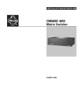
I N S TA L L AT I O N / O P E R AT I O N
ALM2064
®
Alarm Interface Unit
C1517M-A (11/02)
CONTENTS
Section
Page
IMPORTANT SAFEGUARDS AND WARNINGS .................................................................................................................................................................. 3
OVERVIEW .......................................................................................................................................................................................................................... 4
DESCRIPTION ............................................................................................................................................................................................................ 4
FRONT VIEW .............................................................................................................................................................................................................. 4
REAR VIEW ................................................................................................................................................................................................................ 5
INSTALLATION .................................................................................................................................................................................................................... 6
MOUNTING ............................................................................................................................................................................................................... 6
CONNECTING TO THE CM6800 ................................................................................................................................................................................ 6
WIRING ALARMS ...................................................................................................................................................................................................... 7
MAKING THE ALARM CONNECTIONS ........................................................................................................................................................... 10
WIRING EXTERNAL ALARM INPUTS USING ANALOG CIRCUITRY ................................................................................................................ 11
RELAY OUTPUT WIRING ........................................................................................................................................................................................... 12
SETTING THE DIP SWITCHES .................................................................................................................................................................................. 12
OPERATION ........................................................................................................................................................................................................................ 14
TROUBLESHOOTING .......................................................................................................................................................................................................... 15
APPENDIX A ...................................................................................................................................................................................................................... 16
SPECIFICATIONS ................................................................................................................................................................................................................ 18
REGULATORY NOTICES ..................................................................................................................................................................................................... 19
WARRANTY AND RETURN INFORMATION ...................................................................................................................................................................... 19
LIST OF ILLUSTRATIONS
Figure
1
2
3
4
5
6
7
8
9
10
11
12
13
14
15
16
Page
Front View of ALM2064 .................................................................................................................................................................................... 4
Rear View of ALM2064 .................................................................................................................................................................................... 5
Rack-Mount Installation ................................................................................................................................................................................... 6
Connection to the CM6800 .............................................................................................................................................................................. 6
DIP Switch Settings for Supervised/Unsupervised Modes ............................................................................................................................. 7
Supervised Alarm Input Wiring ........................................................................................................................................................................ 8
Unsupervised Alarm Input Wiring .................................................................................................................................................................... 9
Alarm Input Connectors ................................................................................................................................................................................... 10
TTL/CMOS External Alarm Wiring .................................................................................................................................................................. 11
Relay Output Connector .................................................................................................................................................................................. 12
Front Panel Removal ........................................................................................................................................................................................ 12
DIP Switch Location ........................................................................................................................................................................................ 12
SW1 & SW2 Functions .................................................................................................................................................................................... 13
Power Input Fuse Replacement ....................................................................................................................................................................... 15
DB9 Pin-Outs ................................................................................................................................................................................................... 15
ALM2064 Dimension Diagram ........................................................................................................................................................................ 18
LIST OF TABLES
Table
A
B
2
Page
Switch 1 ........................................................................................................................................................................................................... 13
Switch 2 ........................................................................................................................................................................................................... 13
C1517M-A (11/02)
IMPORTANT SAFEGUARDS AND WARNINGS
1. Read, keep, and follow these instructions.
2. Heed all warnings.
3. There are no user-serviceable parts inside this unit. Only authorized service personnel may open the unit.
4. Installation and servicing should only be done by qualified service personnel and conform to all local codes.
5. WARNING: To reduce the risk of fire or electric shock, do not expose this unit to rain or moisture if this unit is designed for indoor
use only.
6. Unless this unit is specifically marked as a NEMA Type 3, 3R, 3S, 4, 4X, 6 or 6P enclosure, it is designed for indoor use only and it
must not be installed where exposed to rain or moisture.
7. Do not expose this unit to dripping or splashing. Do not place objects filled with liquids, such as vases, on this unit.
8. Do not block any ventilation openings. Install in accordance with the manufacturer’s instructions.
9. The installation method and materials should be capable of supporting four times the weight of the unit and equipment.
10. Do not install near any heat source.
11. Only use attachments/accessories specified by the manufacturer.
12. Clean only with dry cloth.
13. Do not defeat the safety purpose of the polarized or grounding-type plug.
14. Protect the power cord from being walked on or pinched, particularly at plugs, convenience receptacles, and the point where they
exit from the unit.
15. Unplug this unit during lightning storms or when unused for long periods of time.
The product and/or manual may bear the following marks:
This symbol indicates that dangerous voltage constituting a risk
of electric shock is present within this unit.
This symbol indicates that there are important operating and
maintenance instructions in the literature accompanying this unit.
CAUTION:
RISK OF ELECTRIC SHOCK.
DO NOT OPEN.
Please thoroughly familiarize yourself with the information in this manual prior to installation and operation.
FOR QUALIFIED SERVICE PERSONNEL ONLY
1. Only use replacement parts recommended by Pelco.
2.
C1517M-A (11/02)
After replacement/repair of this unit’s electrical components, conduct a resistance measurement between line and exposed parts to
verify the exposed parts have not been connected to line circuitry.
3
OVERVIEW
DESCRIPTION
The ALM2064 Alarm Interface Unit provides alarm monitoring capability for up to 64 alarm inputs. Using Pelco’s proprietary M protocol,
the alarm unit communicates with Pelco’s CM6800 matrix switcher via an RS-485 communication interface. The alarm unit can be located
remotely from the system controller and still communicate back to the central system when an alarm occurs.
Other features include the following:
•
Multiple units can be cascaded to provide multiple alarm contact points on a single M port connection.
•
Alarm inputs can be configured in two groups of 32 for supervised or unsupervised mode.
•
The relay output activates when an alarm is triggered.
•
The unit is powered by an auto-ranging power supply.
•
The unit occupies one rack unit (1.75 inches or 4.45 cm), accommodating multiple types of mounting.
FRONT VIEW
The left side of the front panel includes the green power LED light. This light comes on at power-up.
The right side of the front panel includes the red alarm LED. When the light is a solid red, the alarm unit is online. When the light is off,
the unit is offline. In any valid alarm condition, this light starts blinking and only stops when the alarm is no longer active.
When you remove the front panel, you have access to a reset button and configuration DIP switches.
00706
Figure 1. Front View of ALM2064
4
C1517M-A (11/02)
REAR VIEW
The rear of the alarm unit includes the following:
1.
2.
3.
4.
5.
6.
7.
Four groups of alarm inputs (labeled I, II, III, and IV) with removable mating plugs
One alarm output relay
One RS-485 output communication port (RJ-45 connector)
One RS-485 input communication port (RJ-45 connector)
One RS-232 diagnostic communication port (DB9 connector)
A green power LED light, which mirrors the green LED light on the front panel
The grouped input power functions consisting of input power terminals, a fuse, and an on/off switch
POWER
LED, GREEN
SEE FIGURE 8
00707
Figure 2. Rear View of ALM2064
C1517M-A (11/02)
5
INSTALLATION
The following items are supplied:
•
•
•
ALM2064 Alarm Interface Unit
120 VAC power cord
220 VAC power cord
•
•
•
Pelco screwdriver
4 #10 screws with nylon washers
10-foot (3 m) straight RJ-45 cable (8-conductor)
MOUNTING
Install the alarm unit in a 19-inch (48.26 cm) rack. The unit occupies one rack unit (1.75 inches or 4.45 cm) of space. You can mount the
alarm unit to something other than a standard 19-inch rack by relocating the rack ears to another location.
STANDARD 19-INCH (48.26 CM) RACK MOUNT
00708
Figure 3. Rack-Mount Installation
CONNECTING TO THE CM6800
Connect the supplied RJ-45 straight cable from the ALM2064 OUT port to the CM6800 COM 3 port. The active pin-outs are associated
with the four outer pins: 1, 2, 7, and 8. Refer to Figure 4.
If you want to place the alarm unit some distance from the CM6800, the RS-485 communication from the alarm unit to the controller should
not exceed 4,000 feet (1,219 m). You need an RJ-45 wall-block terminal (part number CON12J008Z03G0Z) if operating from a remote site.
To cascade two alarm units, connect a straight cable from the OUT port of the second alarm unit to the IN port of the first alarm unit. The
first unit is the one you connect to the CM6800.
00709
Figure 4. Connection to the CM6800
6
C1517M-A (11/02)
WIRING ALARMS
All alarm wiring takes place using the four groups of connectors located on the rear of the alarm unit. The alarm unit has four groups of
inputs. Each group represents 16 alarm inputs:
•
•
•
•
Group I – 1-8, 9-16
Group II – 17-24, 25-32
Group III – 33-40, 41-48
Group IV – 49-56, 57-64
Each of the four groups of wired alarm inputs are classified into modes (or contact types): supervised and unsupervised. This is important
for the following reasons:
1.
The operational mode (supervised or unsupervised) for each 32-input group is determined solely by the DIP switch positions of SW1.
Refer to Figure 5.
2.
Integrating supervised and unsupervised wiring modes within the same group is not allowed.
3.
In unsupervised mode, it is not possible to have alarms wired for both normally open and normally closed operation in the same
alarm group.
4.
If wiring a group of alarm inputs as supervised, no unwired inputs are allowed as this would result in a constant alarm condition. All
unwired inputs should have a 10-kohm resistor wired across its input and associated GND connection. Refer to Figure 6.
5.
If wiring a group of alarm inputs as unsupervised and normally closed, no unwired inputs are allowed as this would also result in a
constant alarm condition. Alarm inputs not used must be shorted out between the alarm input and its associated GND connection.
Refer to Figure 7.
SW1 – SUPERVISED MODE
1
2
3
4
5
6
7
8
9
10
ON
ALM GROUP
1-32
7 — ON
8 — OFF
ALM GROUP
33-64
9 — ON
10 — OFF
SW1 – UNSUPERVISED MODE
1
2
3
4
5
6
7
8
9
10
ON
00710
ALM GROUP
1-32
7, 8 — OFF, OFF — N.O.
7, 8 — OFF, ON — N.C.
ALM GROUP
33-64
9, 10 — OFF, OFF — N.O
9, 10 — OFF, ON — N.C
Figure 5. DIP Switch Settings for Supervised/Unsupervised Modes
C1517M-A (11/02)
7
SUPERVISED MODE
Use this wiring mode if security is of utmost importance. Alarm inputs wired in supervised mode maximize the detection of tampering by
driving a constant current through a 10-kohm load. If a deviation in the steady current occurs, the alarm goes off. Please note that
unused inputs must also be wired. Refer to Figure 6.
INDIVIDUAL ALARM WIRING CONDITIONS
00711
Figure 6. Supervised Alarm Input Wiring
8
C1517M-A (11/02)
UNSUPERVISED MODE
This wiring mode is easily defeated and should not be used in critical situations. For example, if you wire an alarm as unsupervised and
normally open, and a wire is cut, the alarm does not go off. If wiring for a normally open condition, unused inputs can be left unwired. If
wiring for a normally closed condition, unused inputs must be shorted. Refer to Figure 7.
INDIVIDUAL ALARM WIRING CONDITIONS
00712
Figure 7. Unsupervised Alarm Input Wiring
C1517M-A (11/02)
9
MAKING THE ALARM CONNECTIONS
Each of the four groups contains two connectors with input mating plugs. The top of each mating plug has 16 screw terminals and the
front has 16 pins. The figure below indicates how the pins alternate between alarm inputs and their associated GND (ground) input
connection. For example, pins 1 and 2 are associated with alarm input 1. This applies to all four groups of alarm inputs.
Remove the mating plugs from the connectors to install the wiring. The top connector of each group is for the first eight alarm inputs, and
the bottom connector is for the last eight alarm inputs. The 16 screw terminals secure the alarm wires.
GROUP 1 ALARM INPUTS (1-16) WITH REMOVABLE MATING PLUGS
1
SCREW TERMINALS
ON EACH MATING
PLUG
8
1 2 3 4 5 6 7 8 9 10 11 12 13 14 15 16
ALARM
INPUTS
17 18 19 20 21 22 23 24 25 26 27 28 29 30 31 32
ASSOCIATED
GND INPUT
ADDITIONAL MATING PLUGS SUPPLIED
FOR EACH ALARM INPUT GROUP
MATING PLUG FOR
INPUTS 1-8
MATING PLUG FOR
INPUTS 9-16
ALARM INPUT WIRING SLOTS
NOTE: THE MATING PLUGS HAVE BEEN NUMBERED (1-16, 17-32) FOR DISCUSSION PURPOSES.
MATING PLUG
HEADER PIN #
ALARM INPUT #
MATING PLUG
HEADER PIN #
1
17
ALARM INPUT
18
GND
19
ALARM INPUT
20
GND
21
ALARM INPUT
22
GND
1
ALARM INPUT
2
GND
3
ALARM INPUT
4
GND
5
ALARM INPUT
6
GND
7
ALARM INPUT
8
GND
9
ALARM INPUT
10
GND
11
ALARM INPUT
12
GND
13
ALARM INPUT
14
GND
15
ALARM INPUT
16
GND
2
3
4
5
6
7
8
ALARM INPUT #
23
ALARM INPUT
24
GND
25
ALARM INPUT
26
GND
27
ALARM INPUT
28
GND
29
ALARM INPUT
30
GND
31
ALARM INPUT
32
GND
9
10
11
12
13
14
15
16
00713
Figure 8. Alarm Input Connectors
10
C1517M-A (11/02)
WIRING EXTERNAL ALARM INPUTS USING ANALOG CIRCUITRY
Figure 9 summarizes what is required in supervised and unsupervised modes to wire external alarm inputs using analog TTL/CMOS circuitry rather
than alarms.
ALARM
ALARM
ALARM
ALARM
ALARM
ALARM
00714
Figure 9. TTL/CMOS External Alarm Wiring
C1517M-A (11/02)
11
RELAY OUTPUT WIRING
The alarm unit activates the relay when a valid alarm condition is sensed.
To wire the relay output, you must do the following:
1.
2.
3.
Remove the mating plug from the relay output connector.
Place the wires into the relay out wiring slots.
Tighten the screws to secure the wires.
NOTE: Refer to the REL2064 Installation/Operation Manual for instructions
on wiring relays to peripheral equipment.
00715
Figure 10. Relay Output Connector
SETTING THE DIP SWITCHES
The positioning of the DIP switches for SW1 and SW2 determines how your alarm unit operates. You are able to set the baud rate, alarm
range, alarm group and mode, and local device address.
NOTE: You must recycle power if you make changes to the DIP switches after the alarm unit has been turned on.
1.
2.
3.
Remove the front panel by unscrewing the five flat-head Phillips screws. Refer to Figure 11.
Set the DIP switches. Refer to Tables A and B and Figures 12 and 13.
Replace the front panel.
00716
Figure 11. Front Panel Removal
RESET SWITCH ACCESS
DIP SWITCH 1
DIP SWITCH 2
00717
Figure 12. DIP Switch Location
12
C1517M-A (11/02)
Table A. Switch 1
SW1 – Communications/Alarm Type Selection
Baud
1200
2400
4800
9600
19200
38400
57600
115200
DIP Switch
Off
On
Off
On
Off
On
Off
On
1
Off
Off
On
On
Off
Off
On
On
2
Alarm Range
1-64
65-128
129-192
193-256
257-320
321-384
385-448
449
Off
Off
Off
Off
On
On
On
On
3
Off
On
Off
On
Off
On
Off
On
4
Off
Off
On
On
Off
Off
On
On
5
Off
Off
Off
Off
On
On
On
On
6
Alarm Mode
Norm. Open
(Unsupervised)
Off
Off
Off
Off
Norm. Closed
(Unsupervised)
Off
On
Off
On
Supervised
On
Off
On
Off
*Default to
Norm. Open
On
On
On
On
7
8
9
10
1-32
33-64
*The alarm modes default to normally open when DIP switches 7-10 are set to an invalid condition (all On).
Table B. Switch 2
Address
1
2
3
4
5
6
7
8
9
10
11
12
13
14
15
16
DIP Switch
1
2
3
4
5
6
7
Off
On
Off
On
Off
On
Off
On
Off
On
Off
On
Off
On
Off
On
1
8
Off
Off
On
On
Off
Off
On
On
Off
Off
On
On
Off
Off
On
On
2
9
Off
Off
Off
Off
On
On
On
On
Off
Off
Off
Off
On
On
On
On
3
1
10
Off
Off
Off
Off
Off
Off
Off
Off
Off
Off
Off
Off
Off
Off
Off
Off
7
2
Off
Off
Off
Off
Off
Off
Off
Off
Off
Off
Off
Off
Off
Off
Off
Off
8
3
4
Off
Off
Off
Off
Off
Off
Off
Off
Off
Off
Off
Off
Off
Off
Off
Off
9
5
Off
Off
Off
Off
Off
Off
Off
Off
Off
Off
Off
Off
Off
Off
Off
Off
10
6
7
8
9
10
ON
ON
SERIAL PORT 1
BAUD RATE
1200: OFF, OFF, OFF
2400: ON, OFF, OFF
4800: OFF, ON , OFF
9600: ON, ON, OFF
19200: OFF, OFF, ON
38400: ON, OFF, ON
57600: OFF, ON, ON
115200: ON, ON, ON
Off
Off
Off
Off
Off
Off
Off
Off
On
On
On
On
On
On
On
On
4
SW2 – Address
Off
Off
Off
Off
Off
Off
Off
Off
Off
Off
Off
Off
Off
Off
Off
Off
Off
Off
Off
Off
Off
Off
Off
Off
Off
Off
Off
Off
Off
Off
Off
Off
5
6
BEGIN ALARM RANGE
1-64: OFF, OFF, OFF
65-128: ON, OFF, OFF
129-192: OFF, ON, OFF
193-256: ON, ON, OFF
257-320: OFF, OFF, ON
321-384: ON, OFF, ON
385-448: OFF, ON, ON
449: ON, ON, ON
ALARM GROUP 33-64
N.O. UNSUP: OFF, OFF
N.C. UNSUP: OFF, ON
SUP: ON, OFF
DEFAULT N.O.: ON, ON
ALARM GROUP 1-32
N.O. UNSUP: OFF, OFF
N.C. UNSUP: OFF, ON
SUP: ON, OFF
DEFAULT N.O.: ON, ON
LOCAL DEVICE ADDRESS
NOT USED:
OFF
DIAGNOSTICS: OFF
DEFAULT SETTINGS: LOCAL DEVICE ADDRESS 1, DIP SWITCH 9 OFF, DIP SWITCH 10 ON
NOTE: REFER TO APPENDIX A FOR SETTING EACH DEVICE ADDRESS (1-253)
N.O. = NORMALLY OPEN
N.C. = NORMALLY CLOSED
SUP = SUPERVISED
UNSUP = UNSUPERVISED
DEFAULT SETTINGS: BAUD 19200, ALARM RANGE 1-64, ALARM GROUPS N.O.
00718
Figure 13. SW1 & SW2 Functions
C1517M-A (11/02)
13
OPERATION
The function of the alarm unit is to physically monitor all alarm inputs for a change of state.
Green LEDs on the front and rear panels light when the power is turned on.
The red alarm LED indicates whether the unit is offline or online. This light starts blinking in any valid alarm condition and only stops
when the alarm is no longer active.
For supervised inputs, the unit monitors each alarm input for a constant current through the wiring of the alarm circuit. The alarm consists
of either a 10-kohm resistor connected in series with a normally closed contact or a 10-kohm resistor connected in parallel with a normally
open contact.
For unsupervised inputs, the unit monitors each alarm input for a change of state from that previously defined by DIP switch positions as
being normally open or normally closed. A change from the defined state (normally open to normally closed or normally closed to normally
open) activates an alarm condition.
The alarm unit activates the relay whenever a valid alarm condition is sensed. If multiple alarm points are activated on a given alarm unit,
the relay remains engaged as long as any of these alarm conditions remain active.
14
C1517M-A (11/02)
TROUBLESHOOTING
PROBLEM
SOLUTION
Why is the unit not operating as it should?
Make sure the power cord is plugged in and the power switch is turned on. If the unit
still fails to operate, remove the front panel and press the reset button. Make sure the
DIP switch settings are correct. Check the input power fuse. You may need to replace
it. Refer to Figure 14.
What is the DB9 port used for?
This port is used for diagnostics. A technical support representative may ask you to
enable this feature should a problem arise with the unit. This port is not needed for the
every-day operation of the ALM2064.
00699
Figure 14. Power Input Fuse Replacement
00720
Figure 15. DB9 Pin-Outs
C1517M-A (11/02)
15
APPENDIX A
Address
1
2
3
4
5
6
7
8
9
10
11
12
13
14
15
16
17
18
19
20
21
22
23
24
25
26
27
28
29
30
31
32
33
34
35
36
37
38
39
40
41
42
43
44
45
46
47
48
49
50
51
52
53
54
55
56
57
58
59
60
61
62
0 = OFF
1 = ON
16
1
0
1
0
1
0
1
0
1
0
1
0
1
0
1
0
1
0
1
0
1
0
1
0
1
0
1
0
1
0
1
0
1
0
1
0
1
0
1
0
1
0
1
0
1
0
1
0
1
0
1
0
1
0
1
0
1
0
1
0
1
0
1
2
0
0
1
1
0
0
1
1
0
0
1
1
0
0
1
1
0
0
1
1
0
0
1
1
0
0
1
1
0
0
1
1
0
0
1
1
0
0
1
1
0
0
1
1
0
0
1
1
0
0
1
1
0
0
1
1
0
0
1
1
0
0
3
0
0
0
0
1
1
1
1
0
0
0
0
1
1
1
1
0
0
0
0
1
1
1
1
0
0
0
0
1
1
1
1
0
0
0
0
1
1
1
1
0
0
0
0
1
1
1
1
0
0
0
0
1
1
1
1
0
0
0
0
1
1
DIP Switch
4
5
0
0
0
0
0
0
0
0
0
0
0
0
0
0
0
0
1
0
1
0
1
0
1
0
1
0
1
0
1
0
1
0
0
1
0
1
0
1
0
1
0
1
0
1
0
1
0
1
1
1
1
1
1
1
1
1
1
1
1
1
1
1
1
1
0
0
0
0
0
0
0
0
0
0
0
0
0
0
0
0
1
0
1
0
1
0
1
0
1
0
1
0
1
0
1
0
0
0
0
1
0
1
0
1
0
1
0
1
0
1
0
1
1
1
1
1
1
1
1
1
1
1
1
1
6
0
0
0
0
0
0
0
0
0
0
0
0
0
0
0
0
0
0
0
0
0
0
0
0
0
0
0
0
0
0
0
0
1
1
1
1
1
1
1
1
1
1
1
1
1
1
1
1
1
1
1
1
1
1
1
1
1
1
1
1
1
1
7
0
0
0
0
0
0
0
0
0
0
0
0
0
0
0
0
0
0
0
0
0
0
0
0
0
0
0
0
0
0
0
0
0
0
0
0
0
0
0
0
0
0
0
0
0
0
0
0
0
0
0
0
0
0
0
0
0
0
0
0
0
0
8
0
0
0
0
0
0
0
0
0
0
0
0
0
0
0
0
0
0
0
0
0
0
0
0
0
0
0
0
0
0
0
0
0
0
0
0
0
0
0
0
0
0
0
0
0
0
0
0
0
0
0
0
0
0
0
0
0
0
0
0
0
0
Address
63
64
65
66
67
68
69
70
71
72
73
74
75
76
77
78
79
80
81
82
83
84
85
86
87
88
89
90
91
92
93
94
95
96
97
98
99
100
101
102
103
104
105
106
107
108
109
110
111
112
113
114
115
116
117
118
119
120
121
122
123
124
1
0
1
0
1
0
1
0
1
0
1
0
1
0
1
0
1
0
1
0
1
0
1
0
1
0
1
0
1
0
1
0
1
0
1
0
1
0
1
0
1
0
1
0
1
0
1
0
1
0
1
0
1
0
1
0
1
0
1
0
1
0
1
2
1
1
0
0
1
1
0
0
1
1
0
0
1
1
0
0
1
1
0
0
1
1
0
0
1
1
0
0
1
1
0
0
1
1
0
0
1
1
0
0
1
1
0
0
1
1
0
0
1
1
0
0
1
1
0
0
1
1
0
0
1
1
3
1
1
0
0
0
0
1
1
1
1
0
0
0
0
1
1
1
1
0
0
0
0
1
1
1
1
0
0
0
0
1
1
1
1
0
0
0
0
1
1
1
1
0
0
0
0
1
1
1
1
0
0
0
0
1
1
1
1
0
0
0
0
DIP Switch
4
5
1
1
1
1
0
0
0
0
0
0
0
0
0
0
0
0
0
0
0
0
1
0
1
0
1
0
1
0
1
0
1
0
1
0
1
0
0
1
0
1
0
1
0
1
0
1
0
1
0
1
0
1
1
1
1
1
1
1
1
1
1
1
1
1
1
1
1
1
0
0
0
0
0
0
0
0
0
0
0
0
0
0
0
0
1
0
1
0
1
0
1
0
1
0
1
0
1
0
1
0
0
1
0
1
0
1
0
1
0
1
0
1
0
1
0
1
1
1
1
1
1
1
1
1
6
1
1
0
0
0
0
0
0
0
0
0
0
0
0
0
0
0
0
0
0
0
0
0
0
0
0
0
0
0
0
0
0
0
0
1
1
1
1
1
1
1
1
1
1
1
1
1
1
1
1
1
1
1
1
1
1
1
1
1
1
1
1
7
0
0
1
1
1
1
1
1
1
1
1
1
1
1
1
1
1
1
1
1
1
1
1
1
1
1
1
1
1
1
1
1
1
1
1
1
1
1
1
1
1
1
1
1
1
1
1
1
1
1
1
1
1
1
1
1
1
1
1
1
1
1
8
0
0
0
0
0
0
0
0
0
0
0
0
0
0
0
0
0
0
0
0
0
0
0
0
0
0
0
0
0
0
0
0
0
0
0
0
0
0
0
0
0
0
0
0
0
0
0
0
0
0
0
0
0
0
0
0
0
0
0
0
0
0
(Continued on next page)
C1517M-A (11/02)
Address
125
126
127
128
129
130
131
132
133
134
135
136
137
138
139
140
141
142
143
144
145
146
147
148
149
150
151
152
153
154
155
156
157
158
159
160
161
162
163
164
165
166
167
168
169
170
171
172
173
174
175
176
177
178
179
180
181
182
183
184
185
186
187
188
189
1
0
1
0
1
0
1
0
1
0
1
0
1
0
1
0
1
0
1
0
1
0
1
0
1
0
1
0
1
0
1
0
1
0
1
0
1
0
1
0
1
0
1
0
1
0
1
0
1
0
1
0
1
0
1
0
1
0
1
0
1
0
1
0
1
0
2
0
0
1
1
0
0
1
1
0
0
1
1
0
0
1
1
0
0
1
1
0
0
1
1
0
0
1
1
0
0
1
1
0
0
1
1
0
0
1
1
0
0
1
1
0
0
1
1
0
0
1
1
0
0
1
1
0
0
1
1
0
0
1
1
0
3
1
1
1
1
0
0
0
0
1
1
1
1
0
0
0
0
1
1
1
1
0
0
0
0
1
1
1
1
0
0
0
0
1
1
1
1
0
0
0
0
1
1
1
1
0
0
0
0
1
1
1
1
0
0
0
0
1
1
1
1
0
0
0
0
1
DIP Switch
4
5
1
1
1
1
1
1
1
1
0
0
0
0
0
0
0
0
0
0
0
0
0
0
0
0
1
0
1
0
1
0
1
0
1
0
1
0
1
0
1
0
0
1
0
1
0
1
0
1
0
1
0
1
0
1
0
1
1
1
1
1
1
1
1
1
1
1
1
1
1
1
1
1
0
0
0
0
0
0
0
0
0
0
0
0
0
0
0
0
1
0
1
0
1
0
1
0
1
0
1
0
1
0
1
0
0
1
0
1
0
1
0
1
0
1
0
1
0
1
0
1
1
1
1
1
1
1
1
1
1
1
6
1
1
1
1
0
0
0
0
0
0
0
0
0
0
0
0
0
0
0
0
0
0
0
0
0
0
0
0
0
0
0
0
0
0
0
0
1
1
1
1
1
1
1
1
1
1
1
1
1
1
1
1
1
1
1
1
1
1
1
1
1
1
1
1
1
7
1
1
1
1
0
0
0
0
0
0
0
0
0
0
0
0
0
0
0
0
0
0
0
0
0
0
0
0
0
0
0
0
0
0
0
0
0
0
0
0
0
0
0
0
0
0
0
0
0
0
0
0
0
0
0
0
0
0
0
0
0
0
0
0
0
8
0
0
0
0
1
1
1
1
1
1
1
1
1
1
1
1
1
1
1
1
1
1
1
1
1
1
1
1
1
1
1
1
1
1
1
1
1
1
1
1
1
1
1
1
1
1
1
1
1
1
1
1
1
1
1
1
1
1
1
1
1
1
1
1
1
Address
190
191
192
193
194
195
196
197
198
199
200
201
202
203
204
205
206
207
208
209
210
211
212
213
214
215
216
217
218
219
220
221
222
223
224
225
226
227
228
229
230
231
232
233
234
235
236
237
238
239
240
241
242
243
244
245
246
247
248
249
250
251
252
253
1
1
0
1
0
1
0
1
0
1
0
1
0
1
0
1
0
1
0
1
0
1
0
1
0
1
0
1
0
1
0
1
0
1
0
1
0
1
0
1
0
1
0
1
0
1
0
1
0
1
0
1
0
1
0
1
0
1
0
1
0
1
0
1
0
2
0
1
1
0
0
1
1
0
0
1
1
0
0
1
1
0
0
1
1
0
0
1
1
0
0
1
1
0
0
1
1
0
0
1
1
0
0
1
1
0
0
1
1
0
0
1
1
0
0
1
1
0
0
1
1
0
0
1
1
0
0
1
1
0
3
1
1
1
0
0
0
0
1
1
1
1
0
0
0
0
1
1
1
1
0
0
0
0
1
1
1
1
0
0
0
0
1
1
1
1
0
0
0
0
1
1
1
1
0
0
0
0
1
1
1
1
0
0
0
0
1
1
1
1
0
0
0
0
1
DIP Switch
4
5
1
1
1
1
1
1
0
0
0
0
0
0
0
0
0
0
0
0
0
0
0
0
1
0
1
0
1
0
1
0
1
0
1
0
1
0
1
0
0
1
0
1
0
1
0
1
0
1
0
1
0
1
0
1
1
1
1
1
1
1
1
1
1
1
1
1
1
1
1
1
0
0
0
0
0
0
0
0
0
0
0
0
0
0
0
0
1
0
1
0
1
0
1
0
1
0
1
0
1
0
1
0
0
1
0
1
0
1
0
1
0
1
0
1
0
1
0
1
1
1
1
1
1
1
1
1
1
1
6
1
1
1
0
0
0
0
0
0
0
0
0
0
0
0
0
0
0
0
0
0
0
0
0
0
0
0
0
0
0
0
0
0
0
0
1
1
1
1
1
1
1
1
1
1
1
1
1
1
1
1
1
1
1
1
1
1
1
1
1
1
1
1
1
7
0
0
0
1
1
1
1
1
1
1
1
1
1
1
1
1
1
1
1
1
1
1
1
1
1
1
1
1
1
1
1
1
1
1
1
1
1
1
1
1
1
1
1
1
1
1
1
1
1
1
1
1
1
1
1
1
1
1
1
1
1
1
1
1
8
1
1
1
1
1
1
1
1
1
1
1
1
1
1
1
1
1
1
1
1
1
1
1
1
1
1
1
1
1
1
1
1
1
1
1
1
1
1
1
1
1
1
1
1
1
1
1
1
1
1
1
1
1
1
1
1
1
1
1
1
1
1
1
1
0 = OFF
1 = ON
C1517M-A (11/02)
17
SPECIFICATIONS
ELECTRICAL
Input Voltage:
Power:
Data Ports
Diagnostic:
Input:
Output:
Indicators:
100-240 VAC, 50/60 Hz, auto-ranging
30 VA
Fusing:
Relay Output:
RS-232, DB9 connector
RS-485, RJ-45 connector
RS-485, RJ-45 connector
Two green power LEDs
One red alarm LED
500 mA, 250V
Load rating for relay contacts: 0.50A at 125 VAC or 1A at 25 VAC
GENERAL
Dimensions:
Operating Temperature:
Unit Weight:
See Figure 16.
32° to 122°F (0° to 50°C)
7 lb (3.17 kg)
MECHANICAL
Connectors
Alarms:
Power:
RS-485:
RS-232:
Relay Output:
Four dual-header, 32-input connectors with mating plugs
3-wire receptacle, #18 AWG
Two RJ-45 connectors
One DB9 connector (factory use only)
One 3-pin header with mating plug
(Design and product specifications subject to change without notice.)
8.15
(20.70)
19.00 (48.26)
1.75
(4.45)
PWR
ALARM
ALM2064
Alarm Interface Unit
Made in USA
17.40 (44.20)
00721
Figure 16. ALM2064 Dimension Diagram
18
C1517M-A (11/02)
REGULATORY NOTICES
This equipment has been tested and found to comply with the limits of a Class B digital device, pursuant to part 15 of the FCC rules. These
limits are designed to provide reasonable protection against harmful interference in a residential installation. This equipment generates,
uses, and can radiate radio frequency energy and, if not installed and used in accordance with the instructions, may cause harmful
interference to radio communications. However there is no guarantee that the interference will not occur in a particular installation. If this
equipment does cause harmful interference to radio or television reception, which can be determined by turning the equipment off and on,
the user is encouraged to try and correct the interference by one or more of the following measures:
•
•
•
•
Reorient or relocate the receiving antenna.
Increase the separation between the equipment and the receiver.
Connect the equipment into an outlet on a circuit different from that to which the receiver is connected.
Consult the dealer or an experienced radio/TV technician for help.
WARRANTY AND RETURN INFORMATION
WARRANTY
Pelco will repair or replace, without charge, any merchandise proved defective in material or
workmanship for a period of one year after the date of shipment. Exceptions to this warranty are
as noted below:
• Five years on Pelco manufactured cameras (CC3500/CC3600/CC3700 and MC3500/MC3600
Series); two years on all other cameras.
• Three years on Genex® Series (multiplexers, server, and keyboard) and 090 Series Camclosure®
Camera System.
• Two years on 100/150, 200, and 300 Series Camclosure Camera Systems.
• Two years on all standard motorized or fixed focal length lenses.
• Two years on Legacy®, CM6700/CM6800/CM8500/CM9500/CM9740/CM9760 Matrix, DF5
and DF8 Series Fixed Dome products.
• Two years on Spectra®, Esprit®, and PS20 Scanners, including when used in continuous
motion applications.
• Two years on Esprit and WW5700 series window wiper (excluding wiper blades).
• Eighteen months on DX Series digital video recorders.
• One year (except video heads) on video cassette recorders (VCRs). Video heads will be
covered for a period of six months.
• Six months on all pan and tilts, scanners or preset lenses used in continuous motion applications (that is, preset scan, tour and auto scan modes).
Pelco will warrant all replacement parts and repairs for 90 days from the date of Pelco
shipment. All goods requiring warranty repair shall be sent freight prepaid to Pelco, Clovis,
California. Repairs made necessary by reason of misuse, alteration, normal wear, or accident
are not covered under this warranty.
Pelco assumes no risk and shall be subject to no liability for damages or loss resulting from the
specific use or application made of the Products. Pelco’s liability for any claim, whether based on
breach of contract, negligence, infringement of any rights of any party or product liability, relating
to the Products shall not exceed the price paid by the Dealer to Pelco for such Products. In no
event will Pelco be liable for any special, incidental or consequential damages (including loss of
use, loss of profit and claims of third parties) however caused, whether by the negligence of
Pelco or otherwise.
The above warranty provides the Dealer with specific legal rights. The Dealer may also have
additional rights, which are subject to variation from state to state.
If a warranty repair is required, the Dealer must contact Pelco at (800) 289-9100 or (559) 292-1981 to
obtain a Repair Authorization number (RA), and provide the following information:
1. Model and serial number
2. Date of shipment, P.O. number, Sales Order number, or Pelco invoice number
3. Details of the defect or problem
If there is a dispute regarding the warranty of a product which does not fall under the warranty conditions
stated above, please include a written explanation with the product when returned.
Method of return shipment shall be the same or equal to the method by which the item was received by
Pelco.
RETURNS
In order to expedite parts returned to the factory for repair or credit, please call the factory at (800) 2899100 or (559) 292-1981 to obtain an authorization number (CA number if returned for credit, and RA
number if returned for repair).
All merchandise returned for credit may be subject to a 20% restocking and refurbishing charge.
Goods returned for repair or credit should be clearly identified with the assigned CA or RA number and
freight should be prepaid. Ship to the appropriate address below.
If you are located within the continental U.S., Alaska, Hawaii or Puerto Rico:
Service Department
Pelco
3500 Pelco Way
Clovis, CA 93612-5699
If you are located outside the continental U.S., Alaska, Hawaii or Puerto Rico:
Intermediate Consignee
Ultimate Consignee
American Overseas Air Freight
Pelco
320 Beach Road
3500 Pelco Way
Burlingame, CA 94010
Clovis, CA 93612-5699
USA
USA
REVISION HISTORY
Manual #
C1517M
C1517M-A
Date
5/01
11/02
Comments
Original version.
Updated manual to new format. Revised Table A and updated Table B.
® Pelco, the Pelco logo, Spectra, Genex, Esprit, Camclosure, and Legacy are registered trademarks of Pelco.
C1517M-A (11/02)
© Copyright 2002, Pelco. All rights reserved.
19
®
World Headquarters
3500 Pelco Way
Clovis, California 93612 USA
USA & Canada
Tel: 800/289-9100
Fax: 800/289-9150
International
Tel: 1-559/292-1981
Fax: 1-559/348-1120
www.pelco.com
ISO9001
Orangeburg, New York Las Vegas, Nevada Eindhoven, The Netherlands Wokingham, United Kingdom Montreal, Canada
20
C1517M-A (11/02)