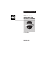
1
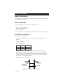
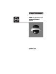
INSTALLATION/OPERATION
®
150 Series Camclosure®
Integrated Camera System
with LowLight™ DSS Technology
In-Ceiling Mount
C2461M-A (7/03)
CONTENTS
Section
Page
IMPORTANT SAFEGUARDS AND WARNINGS ..................................................................................... 3
WELCOME .......................................................................................................................................... 4
INSTALL THE BACK BOX .................................................................................................................... 5
REMOVE THE LOWER DOME .................................................................................................... 5
INSTALL THE BACK BOX ........................................................................................................... 5
ATTACH DIRECTLY TO A WALL/CEILING ......................................................................... 5
ATTACH TO A 4S DEEP ELECTRICAL BOX ........................................................................ 6
INSTALL IN A CEILING TILE .............................................................................................. 7
INSTALL THE CAMERA MODULE ....................................................................................................... 8
CHECK HEATER JUMPER ........................................................................................................... 8
INSTALL AND POSITION THE CAMERA .................................................................................... 9
MAKE CAMERA SETTINGS ................................................................................................................ 10
ZOOM/FOCUS ........................................................................................................................... 10
DIGITAL SLOW SHUTTER (DSS) ............................................................................................... 11
AGC (AUTOMATIC GAIN CONTROL) ........................................................................................ 11
BLC (BACK LIGHT COMPENSATION) ........................................................................................ 11
VERTICAL PHASE ADJUSTMENT (24 VAC OPERATION ONLY) ................................................ 12
HOW TO ADJUST THE PHASE CONTROL ....................................................................... 12
VARIFOCAL LENS AUTO IRIS LEVEL ADJUSTMENT ................................................................ 12
REINSTALL THE DOME AND TRIM RING ........................................................................................... 13
SPECIFICATIONS ............................................................................................................................... 14
WARRANTY AND RETURN INFORMATION ......................................................................................... 15
LIST OF ILLUSTRATIONS
Figure
1
2
3
4
5
6
2
Page
Installation Directly to Wall/Ceiling ..................................................................................... 5
Installation to 4S Deep Electrical Box .................................................................................. 6
Ceiling Tile Installation ......................................................................................................... 7
Heater Jumper and Camera Connector Locations ................................................................ 8
Default Switch Settings and Location of Camera Adjustments .......................................... 10
Dome and Trim Ring Installation .......................................................................................... 13
C2461M-A (7/03)
IMPORTANT SAFEGUARDS AND WARNINGS
1. Installation and servicing should be done only by qualified service personnel and conform to all
local codes.
2. Unless the unit is specifically marked as a NEMA Type 3, 3R, 3S, 4, 4X, 6, or 6P enclosure, it is
designed for indoor use only and must not be installed where exposed to rain and moisture.
3. Use only installation methods and materials capable of supporting four times the maximum
specified load.
4. Use stainless steel hardware to fasten the enclosure to outdoor surfaces.
5. To prevent damage from water leakage when installing an enclosure outdoors, apply sealant
around the bolt holes between the enclosure and mounting surface.
CAUTION
Heater elements could be hot! When camera power is on, use caution
when adjusting the camera.
REGULATORY NOTICES
This equipment has been tested and found to comply with the limits of a Class B digital device,
pursuant to part 15 of the FCC rules. These limits are designed to provide reasonable protection
against harmful interference in a residential installation. This equipment generates, uses, and can
radiate radio frequency energy and, if not installed and used in accordance with the instructions,
may cause harmful interference to radio communications. However there is no guarantee that the
interference will not occur in a particular installation. If this equipment does cause harmful
interference to radio or television reception, which can be determined by turning the equipment off
and on, the user is encouraged to try to correct the interference by one or more of the following
measures:
• Reorient or relocate the receiving antenna.
• Increase the separation between the equipment and the receiver.
• Connect the equipment into an outlet on a circuit different from that to which the receiver is
connected.
• Consult the dealer or an experienced radio/TV technician for help.
C2461M-A (7/03)
3
WELCOME
Thank you for purchasing Pelco’s Camclosure® integrated camera system with LowLight™, DSS
(digital slow shutter) technology. Your new ICS150 Series in-ceiling dome system includes a highresolution, low light, color camera with auto iris and varifocal lens.
The LowLight color camera has extended DSS settings to enhance the low light performance of the
camera by automatically adjusting the number of fields of integration. This slows the picture frame
rate and increases the camera’s sensitivity in low light conditions.
Prior to installation and operation of your new system thoroughly familiarize yourself
with the information in this manual.
4
C2461M-A (7/03)
INSTALL THE BACK BOX
REMOVE THE LOWER DOME
Loosen the tamper-resistant screws with the supplied 1/8-inch hollow screwdriver bit. Remove the
lower dome and place it to the side.
INSTALL THE BACK BOX
The installation methods for the ICS150 back box include the following:
• Attach Directly to a Wall/Ceiling
• Attach to a 4S Deep Electrical Box
• Install in a Ceiling Tile
Select the best method for your installation, and then refer to the following pages for instructions.
Attach Directly to a Wall/Ceiling
Refer to Figure 1 for the following steps.
1. Cut a hole 3.5 inches (9 cm) in diameter in the ceiling or wall using the adapter plate as a
template.
2. Connect the video cable.
3. Connect the power wires.
Voltage
Red Wire
Black Wire
12 VDC
+
Ground
24 VAC
~
~
AC Operation Only – If you are wiring more than one Camclosure system to the same
transformer, connect one side of the transformer to the red wire on all units, and connect the
other side of the transformer to the black wire on all units. Failure to connect all of the units
the same way will cause the cameras to be out of phase with each other and may produce a
vertical roll when switching between cameras.
4. Attach the back box to the wall/ceiling.
MOUNTING
HARDWARE
(NOT SUPPLIED)
WALL OR
CEILING
BACK BOX
Figure 1. Installation Directly to Wall/Ceiling
C2461M-A (7/03)
5
Attach to a 4S Deep Electrical Box
Refer to Figure 2 for the following steps. The installation instructions assume that the 4S box was
previously installed.
1. Attach adapter plate to the 4S box with the two 8-32 x .750-inch screws supplied.
2. Connect the video cable.
3. Connect the power wires.
Voltage
Red Wire
Black Wire
12 VDC
+
Ground
24 VAC
~
~
AC Operation Only – If you are wiring more than one Camclosure system to the same
transformer, connect one side of the transformer to the red wire on all units, and connect the
other side of the transformer to the black wire on all units. Failure to connect all of the units
the same way will cause the cameras to be out of phase with each other and may produce a
vertical roll when switching between cameras.
4. Attach the back box to the adapter plate with the four 8-32 x .375-inch screws supplied.
4S DEEP
ELECTRICAL
BOX
8.32 X .750 SCREW
(SUPPLIED)
WALL OR
CEILING
ADAPTER PLATE
BACK BOX
8.32 X .375 SCREW
(SUPPLIED)
Figure 2. Installation to 4S Deep Electrical Box
6
C2461M-A (7/03)
Install in a Ceiling Tile
Refer to Figure 3 for the following steps.
1. Cut a hole 3.5 inches (9 cm) in diameter in the ceiling tile for the back box. Use the adapter
plate as a template.
2. Punch four screw holes in the ceiling tile. Use the four threaded screw holes in the adapter
plate as a template.
3. Attach the back box to the ceiling tile and adapter plate with the four 8-32 x 1.25-inch screws
supplied.
4. Replace the ceiling tile.
5. Remove an adjacent ceiling tile and connect the video cable.
6. Connect the power wires.
Voltage
Red Wire
Black Wire
12 VDC
+
Ground
24 VAC
~
~
AC Operation Only – If you are wiring more than one Camclosure system to the same
transformer, connect one side of the transformer to the red wire on all units, and connect the
other side of the transformer to the black wire on all units. Failure to connect all of the units
the same way will cause the cameras to be out of phase with each other and may produce a
vertical roll when switching between cameras.
ADAPTER PLATE
CEILING TILE
8-32 X 1.25
MOUNTING
HARDWARE
(SUPPLIED)
BACK BOX
Figure 3. Ceiling Tile Installation
C2461M-A (7/03)
7
INSTALL THE CAMERA MODULE
CHECK HEATER JUMPER
The Camclosure is equipped with a heater to defrost the dome. Some installations may not require
this heater. If the unit will never be subjected to a frost temperature, you can disable the heater,
saving power requirements. To disable the heater, remove the jumper cover from the J1 jumper
block (refer to Figure 4). It is recommended that the jumper cover be left in the unit by installing it
on one of the jumper pins.
CAMERA CONNECTOR
J1 JUMPER
Figure 4. Heater Jumper and Camera Connector Locations
8
C2461M-A (7/03)
INSTALL AND POSITION THE CAMERA
1. Plug the video connector from the camera into the mating connector inside the back box (refer
to Figure 4).
2. Position the camera so that the tab on the camera bracket is pointing out of the enclosure,
away from the ceiling or wall. Refer to the following illustrations for proper camera installation.
CAMERA BRACKET
TAB ALWAYS POINTS
OUT OF THE
ENCLOSURE
TOP OF
CAMERA
CAMERA BRACKET
TAB ALWAYS POINTS
OUT OF THE
ENCLOSURE
Wall Mounting - The camera bracket tab
points out of the enclosure and the top of the
camera points up towards the tab.
Ceiling Mounting - The camera bracket tab
points out of the enclosure and the top of the
camera is pointed in the opposite direction.
3. Install the camera bracket. Gently squeeze the bracket, place it against the shoulder inside the
back box, and gently release.
4. Turn on power to the camera and monitor.
C2461M-A (7/03)
9
MAKE CAMERA SETTINGS
CAUTION: Heater elements could be hot! When camera power is on, use caution when adjusting
the camera. This applies to all models.
DSS2
DSS1
AGC
BLC
ON
OFF
WHITE INDICATES
SWITCH SETTING
LEVEL
PHASE
N
W
ZOOM
FOCUS
T
Figure 5. Default Switch Settings and Location of Camera Adjustments
ZOOM/FOCUS
1. Select a field of view by turning the zoom adjustment ring clockwise/counterclockwise. Refer
to Figure 5.
2. Tighten the zoom locking screw.
3. Adjust the focus by moving the focus locking screw clockwise/counterclockwise.
4. Tighten the focus locking screw.
10
C2461M-A (7/03)
DIGITAL SLOW SHUTTER (DSS)
Digital slow shutter slows the picture frame rate and increases the camera sensitivity under low
light conditions. Depending on the number of fields of integration the picture will develop a
granular appearance and motion may show some lag, resulting in a stereoscopic effect or streaking
on fast moving objects. These effects increase as the number of fields of integration increase.
Available settings include the following:
ON OFF
30 fields of integration maximum (default setting) – 1/2-second scene update rate.
16 fields of integration maximum – 1/4-second scene update rate.
4 fields of integration maximum – 1/15-second scene update rate.
OFF – Disables the DSS mode.
Digital slow shutter automatically adjusts the number of fields of integration depending on the light
level of the viewed scene, up to the maximum determined by the switch settings.
AGC (AUTOMATIC GAIN CONTROL)
AGC automatically adjusts the image to compensate for changes in light levels.
ON (Default setting) - Enables the AGC mode.
OFF - Disables the AGC mode.
BLC (BACK LIGHT COMPENSATION)
The BLC (backlight compensation) feature compensates for backlit scenes by enhancing objects in
the center of the scene.
OFF (Default setting) - Disables the BLC mode.
ON - Enables the BLC mode. Use this setting if a bright backlight is present and the subject in the
center of the picture appears dark or as a silhouette.
C2461M-A (7/03)
11
VERTICAL PHASE ADJUSTMENT (24 VAC OPERATION ONLY)
When using more than one camera power supply, a brief vertical roll may occur on the monitor
when a camera view is switched. To eliminate vertical roll reverse the 24 VAC connections on one
camera. If both cameras are connected to the same transformer, this should solve the problem. If
reversing the connections does not solve the problem, adjust the phase control by synchronizing, or
line-locking, the cameras to one another.
How to Adjust the Phase Control
It may be necessary to have two people in communication when synchronizing the cameras: one
person at the camera and another person at the monitor to observe the vertical roll and the effect
of any adjustments made at the camera.
To synchronize the cameras:
1. Choose a reference camera to which all other cameras will be phased.
2. Select a camera and synchronize it to the reference camera by turning the phase adjustment
control (refer to Figure 5) clockwise and/or counterclockwise.
3. Each time an adjustment is made, switch back and forth between the camera you are adjusting
and the reference camera. Repeat this process as many times as necessary, until the roll
between the cameras is no longer noticeable.
4. Adjust the phase of all other cameras by repeating steps 2 through 3. Always adjust to the
reference camera selected in step 1.
NOTE: The preferred method for camera phase adjustment is to use a dual trace oscilloscope to align
the vertical synchronization pulses of the reference camera to the selected camera(s).
VARIFOCAL LENS AUTO IRIS LEVEL ADJUSTMENT
To adjust the auto iris level, turn the level adjustment counterclockwise to decrease the brightness
and clockwise to increase the brightness level.
12
C2461M-A (7/03)
REINSTALL THE DOME AND TRIM RING
Place the trim ring and dome over the back box. If the dome has a liner, position the viewing window
over the lens of the camera. Tighten the tamper-resistant screws with the supplied 1/8-inch hollow
screwdriver bit. Note that the screws are installed at an angle.
PRODUCT WARRANTY AND RETURN INFORMATION
Figure 6. Dome and Trim Ring Installation
WARRANTY
Pelco will repair or replace, without charge, any merchandise proved defective in material or
workmanship for a period of one year after the date of shipment.
Exceptions to this warranty are as noted below:
• Five years on FR/FT/FS Series fiber optic products and TW3000 Series unshielded twisted
pair transmission products.
• Three years on Genex® Series products (multiplexers, server, and keyboard).
• Three years on Camclosure® and fixed camera models, except the CC3701H-2,
CC3701H-2X, CC3751H-2, CC3651H-2X, MC3651H-2, and MC3651H-2X camera models,
which have a five-year warranty.
• Three years on PMCL200/300/400 Series LCD monitors.
• Two years on standard motorized or fixed focal length lenses.
• Two years on Legacy®, CM6700/CM6800/CM9700 Series matrix, and DF5/DF8 Series fixed
dome products.
• Two years on Spectra®, Esprit®, ExSite™, and PS20 scanners, including when used in
continuous motion applications.
• Two years on Esprit® and WW5700 Series window wiper (excluding wiper blades).
• Two years (except lamp and color wheel) on Digital Light Processing (DLP®) displays.
The lamp and color wheel will be covered for a period of 90 days. The air filter is not
covered under warranty.
• Eighteen months on DX Series digital video recorders, NVR300 Series network video
recorders, and Endura™ Series distributed network-based video products.
• One year (except video heads) on video cassette recorders (VCRs). Video heads will be
covered for a period of six months.
• Six months on all pan and tilts, scanners or preset lenses used in continuous motion
applications (that is, preset scan, tour and auto scan modes).
Pelco will warrant all replacement parts and repairs for 90 days from the date of Pelco
shipment. All goods requiring warranty repair shall be sent freight prepaid to Pelco, Clovis,
California. Repairs made necessary by reason of misuse, alteration, normal wear, or accident
are not covered under this warranty.
Pelco assumes no risk and shall be subject to no liability for damages or loss resulting from
the specific use or application made of the Products. Pelco’s liability for any claim, whether
based on breach of contract, negligence, infringement of any rights of any party or product liability, relating to the Products shall not exceed the price paid by the Dealer to Pelco for such
Products. In no event will Pelco be liable for any special, incidental or consequential damages
(including loss of use, loss of profit and claims of third parties) however caused, whether by
the negligence of Pelco or otherwise.
The above warranty provides the Dealer with specific legal rights. The Dealer may also have
additional rights, which are subject to variation from state to state.
If a warranty repair is required, the Dealer must contact Pelco at (800)þ289-9100 or
(559) 292-1981 to obtain a Repair Authorization number (RA), and provide the following
information:
1. Model and serial number
2. Date of shipment, P.O. number, Sales Order number, or Pelco invoice number
3. Details of the defect or problem
If there is a dispute regarding the warranty of a product which does not fall under the
warranty conditions stated above, please include a written explanation with the product when
returned.
Method of return shipment shall be the same or equal to the method by which the item was
received by Pelco.
RETURNS
In order to expedite parts returned to the factory for repair or credit, please call the factory at
(800) 289-9100 or (559) 292-1981 to obtain an authorization number (CA number if returned for
credit, and RA number if returned for repair).
All merchandise returned for credit may be subject to a 20% restocking and refurbishing
charge.
Goods returned for repair or credit should be clearly identified with the assigned CA or RA
number and freight should be prepaid. Ship to the appropriate address below.
If you are located within the continental U.S., Alaska, Hawaii or Puerto Rico, send goods to:
Service Department
Pelco
3500 Pelco Way
Clovis, CA 93612-5699
If you are located outside the continental U.S., Alaska, Hawaii or Puerto Rico and are
instructed to return goods to the USA, you may do one of the following:
If the goods are to be sent by a COURIER SERVICE, send the goods to:
Pelco
3500 Pelco Way
Clovis, CA 93612-5699 USA
If the goods are to be sent by a FREIGHT FORWARDER, send the goods to:
Pelco c/o Expeditors
473 Eccles Avenue
South San Francisco, CA 94080 USA
Phone: 650-737-1700
Fax: 650-737-0933
The materials used in the manufacture of this document and its components are compliant to the requirements of Directive 2002/95/EC.
ThisThis
equipment
contains
electrical
or electronic
components
that must
be must
recycled
comply with
Directive
of the European
Union
equipment
contains
electrical
or electronic
components
that
be properly
recycledtoproperly
to comply
with2002/96/EC
Directive 2002/96/EC
of the
European Union
regarding the disposal of waste electrical and electronic equipment (WEEE). Contact your local dealer for procedures for recycling this equipment.
regarding the disposal of waste electrical and electronic equipment (WEEE). Contact your local dealer for procedures for recycling this equipment.
C2461M-A (7/03)
13
SPECIFICATIONS
BACKBOX
Electrical
Input Voltage:
Power Consumption:
Video Connector:
12 VDC or 24 VAC, ±10%, auto-sensing
13 watts or less
BNC
General
Operating Temperature: -50° to 122°F (-46° to 50°C)
De-ices to 25°F (-4°C)
Pan/Tilt Adjustment:
Manual; 360° pan; 180° tilt
Construction:
Aluminum with steel camera mounting bracket and polycarbonate dome
Finish:
White polyester powder coat
Dimensions
Above Ceiling:
1.75 (H) x 3.50 (W) inches
(4.45 x 8.89 cm)
Below Ceiling:
2.42 (H) x 5.48 (W) inches
(6.15 x 13.90 cm)
Bubble:
3.75-inch diameter
Environment:
Indoor/outdoor
Weight:
1.70 lb (0.77 kg)
CAMERA
Signal System:
Imaging Device:
Resolution:
Min. Illumination:
Lens:
Synchronize:
Iris Control:
Signal to Noise:
AGG:
BLC:
Auto Iris Type:
Shutter:
Video Level:
NTSC/PAL
1/3-inch interline transfer CCD
480 TV lines
0.75 lux @ 40 IRE, DSS off, f1.6 @ wide angle
1.20 lux @ 50 IRE, DSS off, f1.6 @ wide angle
0.025 lux @ 40 IRE, 30 fields of DSS, f1.6 @ wide angle
0.040 lux @ 50 IRE, 30 fields of DSS, f1.6 @ wide angle
2.6-6.0 mm or 4.0-9.0 mm varifocal, D-mount, f1.6
Adjustable AC line lock/internal, auto select
Electronic/automatic
50 dB
Selectable, on/off
DIP switch selectable, ON/OFF
DC drive
1/60-1/100,000 electronic, auto
Adjustable
CERTIFICATIONS
NTSC Models:
PAL Models:
UL, cUL, and FCC Class B
CE Class B, UL, cUL, and FCC Class B
(Design and product specifications subject to change without notice.)
14
C2461M-A (7/03)
WARRANTY AND RETURN INFORMATION
WARRANTY
Pelco will repair or replace, without charge, any merchandise proved defective in material or workmanship for a period of one year after the date of
shipment. Exceptions to this warranty are as noted below:
•
•
•
•
•
•
•
•
•
•
Five years on Pelco manufactured cameras (CC3500/CC3600/CC3700 and MC3500/MC3600 Series); two years on all other cameras.
Three years on Genex® Series (multiplexers, server, and keyboard) and 090 Series Camclosure® Camera System.
Two years on 100/150, 200, and 300 Series Camclosure Camera Systems.
Two years on all standard motorized or fixed focal length lenses.
Two years on Legacy®, CM6700/CM6800/CM6800E/CM8500/CM9500/CM9740/CM9760 Matrix, DF5 and DF8 Series Fixed Dome products.
Two years on Spectra®, Esprit®, and PS20 Scanners, including when used in continuous motion applications.
Two years on Esprit and WW5700 series window wiper (excluding wiper blades).
Eighteen months on DX Series digital video recorders.
One year (except video heads) on video cassette recorders (VCRs). Video heads will be covered for a period of six months.
Six months on all pan and tilts, scanners or preset lenses used in continuous motion applications (that is, preset scan, tour and auto scan modes).
Pelco will warrant all replacement parts and repairs for 90 days from the date of Pelco shipment. All goods requiring warranty repair shall be sent
freight prepaid to Pelco, Clovis, California. Repairs made necessary by reason of misuse, alteration, normal wear, or accident are not covered under
this warranty.
Pelco assumes no risk and shall be subject to no liability for damages or loss resulting from the specific use or application made of the Products.
Pelco’s liability for any claim, whether based on breach of contract, negligence, infringement of any rights of any party or product liability, relating to
the Products shall not exceed the price paid by the Dealer to Pelco for such Products. In no event will Pelco be liable for any special, incidental or
consequential damages (including loss of use, loss of profit and claims of third parties) however caused, whether by the negligence of Pelco or
otherwise.
The above warranty provides the Dealer with specific legal rights. The Dealer may also have additional rights, which are subject to variation from
state to state.
If a warranty repair is required, the Dealer must contact Pelco at (800) 289-9100 or (559) 292-1981 to obtain a Repair Authorization number (RA), and
provide the following information:
1. Model and serial number
2. Date of shipment, P.O. number, Sales Order number, or Pelco invoice number
3. Details of the defect or problem
If there is a dispute regarding the warranty of a product which does not fall under the warranty conditions stated above, please include a written
explanation with the product when returned.
Method of return shipment shall be the same or equal to the method by which the item was received by Pelco.
RETURNS
In order to expedite parts returned to the factory for repair or credit, please call the factory at (800) 289-9100 or (559) 292-1981 to obtain an
authorization number (CA number if returned for credit, and RA number if returned for repair).
All merchandise returned for credit may be subject to a 20% restocking and refurbishing charge.
Goods returned for repair or credit should be clearly identified with the assigned CA or RA number and freight should be prepaid. Ship to the
appropriate address below.
If you are located within the continental U.S., Alaska, Hawaii or
Puerto Rico:
Service Department
Pelco
3500 Pelco Way
Clovis, CA 93612-5699
If you are located outside the continental U.S., Alaska, Hawaii or
Puerto Rico:
Intermediate Consignee
Ultimate Consignee
American Overseas Air Freight
Pelco
320 Beach Road
3500 Pelco Way
Burlingame, CA 94010
Clovis, CA 93612-5699
USA
USA
® Pelco, the Pelco logo, Spectra, Genex, Esprit, Camclosure, and Legacy are registered trademarks of Pelco.
© Copyright 2003, Pelco. All rights reserved.
REVISION HISTORY
Manual #
C2461M
C2461M-A
Date
4/03
7/03
C2461M-A (7/03)
Comments
Preliminary manual for beta testing.
Final version.
15
®
World Headquarters
3500 Pelco Way
Clovis, California 93612 USA
USA & Canada
Tel: 800/289-9100
Fax: 800/289-9150
International
Tel: 1-559/292-1981
Fax: 1-559/348-1120
www.pelco.com
ISO9001
Orangeburg, New York Las Vegas, Nevada Eindhoven, The Netherlands Wokingham, United Kingdom Montreal, Canada