1
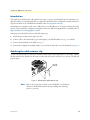
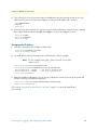
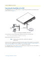
For
For Quick
Quick
Start
Start Installation
Installation
SmartNode 4400
IpChannel Bank
Quick Start Guide
Important
This is a Class A device and is intended for use in a light industrial environment. It is not intended nor approved for use in an industrial
or residential environment.
Sales Office: +1 (301) 975-1000
Technical Support: +1 (301) 975-1007
E-mail: [email protected]
WWW: www.patton.com
Part Number: 07MSN4400-QS, Rev. B
Revised: January 13, 2010
Patton Electronics Company, Inc.
7622 Rickenbacker Drive
Gaithersburg, MD 20879 USA
Tel: +1 (301) 975-1000
Fax: +1 (301) 869-9293
Support: +1 (301) 975-1007
Web: www.patton.com
E-mail: [email protected]
Trademark Statement
The terms SmartNode, SmartWare, and SmartView are trademarks of Patton
Electronics Company. All other trademarks presented in this document are the property of their respective owners.
Copyright © 2010, Patton Electronics Company. All rights reserved.
The information in this document is subject to change without notice. Patton Electronics assumes no liability for errors that may appear in this document.
Important Information
To use virtual private network (VPN) and/or AES/DES/3DES encryption capabilities
with the SmartNode 4400, you may need to purchase additional licenses, hardware,
software, network connection, and/or service. Contact [email protected] or
+1 (301) 975-1000 for assistance.
Warranty Information
The software described in this document is furnished under a license and may be used
or copied only in accordance with the terms of such license. For information about the
license, go to www.patton.com.
Patton Electronics warrants all SmartNode router components to be free from defects,
and will—at our option—repair or replace the product should it fail within one year
from the first date of the shipment.
This warranty is limited to defects in workmanship or materials, and does not cover
customer damage, abuse or unauthorized modification. If the product fails to perform
as warranted, your sole recourse shall be repair or replacement as described above.
Under no condition shall Patton Electronics be liable for any damages incurred by the
use of this product. These damages include, but are not limited to, the following: lost
profits, lost savings and incidental or consequential damages arising from the use of or
inability to use this product. Patton Electronics specifically disclaims all other warranties, expressed or implied, and the installation or use of this product shall be deemed
an acceptance of these terms by the user.
SmartNode 4400 Quick Start Guide
Safety when working with electricity
The SmartNode contains no user serviceable parts. The equipment shall be
returned to Patton Electronics for repairs, or repaired by qualified service personnel. Opening the SmartNode case will void the warranty.
Mains Voltage: Do not open the case the when the power cord is attached.
Line voltages are present within the power supply when the power cords are
connected. The mains outlet that is utilized to power the device shall be
within 10 feet (3 meters) of the device, shall be easily accessible, and protected by a circuit breaker.
For AC powered units, ensure that the power cable used meets all applicable
standards for the country in which it is to be installed, and that it is connected
to a wall outlet which has earth ground.
The Model SN4400 is not shipped with power cables. For AC powered units,
ensure that the power cable used meets all applicable standards for the country in which it is to be installed, and that it is connected to a wall outlet which
has earth ground.
Hazardous network voltages are present in WAN ports regardless of whether
power to the SmartNode is ON or OFF. To avoid electric shock, use caution
when near WAN ports. When detaching the cables, detach the end away from
the SmartNode first.
Because telephone line voltages can be dangerous, when detaching the network cables, disconnect the end away from the SmartNode first.
Do not work on the system or connect or disconnect cables during periods of
lightning activity.
In accordance with the requirements of council directive 2002/
96/EC on Waste of Electrical and Electronic Equipment (WEEE),
ensure that at end-of-life you separate this product from other
waste and scrap and deliver to the WEEE collection system in
your country for recycling.
Safety when working with electricity
3
SmartNode 4400 Quick Start Guide
Introduction
This Quick Start Guide leads you through the basic steps to set up a new SmartNode and to download a configuration. Please note that this guide does not replace the detailed Software Configuration Guide and the Getting Started Guide on the CD-ROM and available online at www.patton.com/voip.
SmartNodes can be used for a wide variety of IP and voice over IP applications. To support and ease the configuration of the SmartNodes, configuration templates for the most important applications are available online at
http://www.patton.com/voip/appnotes.shtml.
Setting up a new SmartNode consists of the following steps:
1. Attach the power cable retainer clip to the unit
2. Connect a PC to the SmartNode, log in and configure your LAN IP address (see page 5 for details)
3. Connect the SmartNode to the LAN (see page 7)
4. Download a configuration example, adapt it to your network, and load it onto the SmartNode (see page 8)
Attaching the cable retainer clip
To secure the power cord, it is necessary to attach the metal retainer clip (if applicable to your model). Squeeze
the clip and insert into the holes in the screws on either side of the power connector on your unit. The clip will
pop into place.
Power cable
retainer clip
Figure 1. Attaching the cable retainer clip
Note
Introduction
Refer to the Getting Started Guide on the CD-ROM or on the Patton
website for detailed instrauctions about grounding and connecting
power to your unit.
4
SmartNode 4400 Quick Start Guide
Connecting a PC, logging in, and configuring the LAN IP address
Connecting power and configuring the default IP address
Connect the SmartNode to the mains power supply using the included power supply and cable. When the
RUN LED stops blinking and remains lit, the SmartNode is ready.
The factory default IP settings are listed in table 1. If these addresses do not work with your network they must
be changed. Contact your network administrator if you are not sure which IP address to use in
your installation.
Table 1. Factory default IP address and network mask configuration
IP Addresss(es)
Network Mask
DHCP
DHCP
192.168.1.1
255.255.255.0
192.168.1.10-192.168.1.19
255.255.255.0
Item
WAN interface Ethernet 0 (ETH 0/0)
LAN interface Ethernet 1 (ETH 0/1)
DHCP server address range
Note
The DHCP server is running on the ETH 0/1 of the SN4400 Series
models. All Ethernet ports are pre-configured and active.
lco
Te
IT
DI
UN
IN
IC
EQ
SC UI
PP
ON
ED
BE NE
FO CT WIT
RE BO H
DU
SE TH
AL
RV SU
SU
PP PP
G LIE LIE
S S
Connecting to a PC and logging in
1. To access the SmartNode configuration, connect a PC equipped with an RS-232 console port to the Console port on the front of the SmartNode. Use the included black Ethernet cable and RJ45 to DB-9 adapter
for this purpose (Model 16F-561).
0V
24
0- Hz)
10 60 P
0(5 AM
1
rts
Po
50
ole
ns
Co
t
se
Re
H
Console port
0/0
ET
H
0/1
ET
Model 16F-561
adapter and cable
Laptop PC
Figure 2. Connecting to the PC
2. Open a Terminal connection to the SmartNode. Use the Terminal program included with most PC operating systems (e.g. Hyper Terminal on Windows). The CD-ROM also includes some recommended terminal programs.
Connecting a PC, logging in, and configuring the LAN IP address
5
SmartNode 4400 Quick Start Guide
3. Type administrator as the login prompt and press the Enter key after the password prompt (do not type
anything for the password). A prompt will appear consisting of the IP address and > character.
login:administrator
password:
172.16.40.1>
4. Following log in, the SmartNode is in operator execution mode (indicated by > character in the command
line prompt). With the commands enable and configure, you enter the configuration mode.
172.16.40.1>enable
172.16.40.1#configure
172.16.40.1(cfg)#
Changing the IP address
1. Select the context IP mode to configure an IP interface.
172.16.40.1(cfg)#context ip router
172.16.40.1(ctx-ip)[router]#
2. Set the IP address and network mask for the each IP interface (eth0, for example).
Note
For the examples in this guide, a private network (172.16.1) IP
address is used.
172.16.40.1(ctx-ip)[router]#interface eth0
172.16.40.1(if-ip)[eth0]#ipaddress 172.16.1.10 255.255.255.0
2002-10-29T00:09:40 : LOGINFO
: Link down on interface eth0.
2002-10-29T00:09:40 : LOGINFO
: Link up on interface eth0.
172.16.1.10(if-ip)[eth0]#
3. Make this modified configuration your new start-up configuration. On the next start-up the system will
initialize itself using the modified configuration.
172.16.1.10 (if-ip)[eth0]#copy running-config startup-config
172.16.1.10 (if-ip)[eth0]#
Go to section “Connecting the SmartNode to the LAN” on page 7 to connect the SmartNode to
your network.
Connecting a PC, logging in, and configuring the LAN IP address
6
SmartNode 4400 Quick Start Guide
Connecting the SmartNode to the LAN
UN
IN
IC
IT
EQ
DI
SC UI
PP
ON
ED
BE NE
FO CT WIT
RE BO H
DU
SE TH
AL
RV SU
SU
PP PP
G LIE LIE
S S
The 4400 Ethernet ports are auto MDX, therefore a straight-through wired cable can be used for host and
switch connections (see figure 3).
lco
Te
rts
Po
50
ole
ns
Co
t
se
Re
H
0/0
ET
H
0/1
ET
WAN
(ETH 0/0)
LAN
Network
interface
PC or workstation
or Telnet
LAN (ETH 0/1)
Internet or
WAN (optional)
Figure 3. Connecting the SmartNode to the network
You can check the connection with the ping command to another host on the local LAN.
172.16.1.99(if-ip)[eth0]#ping <IP Address of the host>
Respectively from the host: ping 172.16.1.99
Note
To ping outside your local LAN, you will need to configure the
default gateway.
You may now start to configure the SmartNode from scratch using the CLI commands, but we recommend
that you start your configuration from a template. See “Downloading a configuration example, adapting it to
your network, and loading it onto the SmartNode” on page 8 for further details.
For a detailed description of the CLI refer to the SmartWare Software Configuration Guide (SCG) available on
the CD-ROM and online at: www.patton.com/voip.
Connecting the SmartNode to the LAN
7
SmartNode 4400 Quick Start Guide
Downloading a configuration example, adapting it to your network,
and loading it onto the SmartNode
Patton provides a collection of configuration templates on the CD-ROM that came with the SmartNode
device—and also on the support page at www.patton.com/voip/appnotes.shtml—one of which may be similar enough to your application that you can use it to speed up configuring the SmartNode. Simply download
the configuration note that matches your application to your PC. Adapt the configuration as described in the
configuration note to your network (remember to modify the IP address) and copy the modified configuration
to a TFTP server. The SmartNode can now load its configuration from this server.
Note
Patton regularly adds new configuration templates to the collection at
www.patton.com/voip/appnotes.shtml, so if you do not see your application on the CD-ROM, it may have been added to the website.
Note
If your application is unique and not covered by any of Patton’s configuration templates, you can manually configure the SmartNode instead of loading a configuration file template. In that case, refer to the SmartNode Series
SmartWare Software Configuration Guide for information on configuring the
SmartNode device.
In this example we assume the TFTP server on the host with the IP address 172.16.1.11 and the configuration
named SN.cfg in the root directory of the TFTP server.
172.16.1.99(if-ip)[eth0]#copy tftp://172.16.1.11/SN.cfg startup-config
Download...100%
172.16.1.99(if-ip)[eth0]#
After the SmartNode has been rebooted the new startup configuration will be activated.
IMPORTANT
When you issue the reload command, the SmartNode will ask
if you want to copy the running configuration to the startup configuration. Since you just downloaded a configuration file to the
startup configuration you must answer this question with NO.
Otherwise, the downloaded configuration will be overwritten
and lost!
172.16.1.99(if-ip)[eth0]#reload
Running configuration has been changed.
Do you want to copy the 'running-config' to the 'startup-config'?
Press 'yes' to store, 'no' to drop changes : no
Press 'yes' to restart, 'no' to cancel : yes
The system is going down
Additional information
For detailed information about configuring and operating guidance, set up procedures, and troubleshooting,
refer to the SmartNode Series SmartWare Software Configuration Guide and the SmartNode Getting Started Guide
on the enclosed Patton VoIP CD-ROM or at http://www.patton.com/voip/. On the CD-ROM you will also
find numerous freeware and shareware tools, including TFTP servers, Telnet clients, etc..
Downloading a configuration example, adapting it to your network, and loading it onto the SmartNode
8
SmartNode 4400 Quick Start Guide
Compliance
EMC compliance:
• FCC Part 15, Class A
• EN55022, Class A
• EN55024
• EN-61000-3-2 Harmonics
• EN-61000-3-3 Flicker
• EN-61000-4-2 ESD
• EN-61000-4-3 Radiated Immunity
• EN-61000-4-4 EFT
• EN-61000-4-5 Surge
• EN-61000-4-6 Low Frequency Common Immunity
• EN-61000-4-11 Voltage Dips and Sags
Safety compliance:
• UL60950-1/CSA C22.2 No. 60950-1
• IEC/EN 60950-1
• AS/NZS 60950-1
CE Declaration of Conformity
This equipment conforms to the requirements of Council Directive 1999/5/EC on the approximation of the
laws of the member states relating to Radio and Telecommunication Terminal Equipment and the mutual recognition of their conformity.
The safety advice in the documentation accompanying this product shall be obeyed. The conformity to the
above directive is indicated by CE sign on the device.
The signed Declaration of Conformity can be downloaded at www.patton.com/certifications.
Authorized European Representative
D R M Green
European Compliance Services Limited.
Avalon House, Marcham Road
Abingdon,
Oxon OX14 1UD, UK
Compliance
9
SmartNode 4400 Quick Start Guide
NOTES
NOTES
10
SmartNode 4400 Quick Start Guide
NOTES
NOTES
11
SmartNode 4400 Quick Start Guide
NOTES
NOTES
12