1
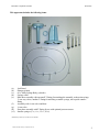
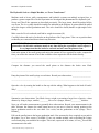
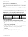
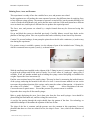
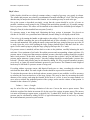
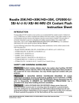
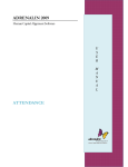
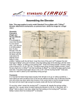
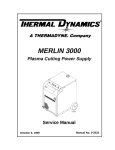
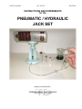
PASCO scientific 012-12537A INSTRUCTIONS AND EXPERIMENTS for the PNEUMATIC / HYDRAULIC JACK SET Designed and manufactured by… SE-8764A Pneumatic / Hydraulic Jack Set SE-8764A Notes to the Teacher Description The Transparent Devices Hydraulic/Pneumatic Jack Set includes a rugged stand that holds a large cylinder-and-piston syringe, four smaller syringes, and flexible tubing assemblies with valves and quick-connect fittings, together with this manual. Purpose This set makes possible a number of teacher demonstrations and student experiments involving fluids and air. These include: The operation of a pump The hydraulic/pneumatic jack as a force transformer (simple machine) The difference in the ability of gases to compress compared to liquids Force, area, and the concept of pressure Boyle’s law, using air or other gases Care and use Some simple precautions will help ensure that this set provides years of use: When lifting a load such as a stack of books, center the load, do not lift too heavy a load, and do not lift the load above the 40 cc mark on the syringe. If lubrication of the syringes is needed, use only glycerin or silicone oil. Do not use petroleumbased lubricants, as this will quickly damage the seals. Use only light finger pressure on the quick-connect fittings. Do not over-tighten. If lost or damaged, replacement parts are available. Safety Please teach and expect safe behavior in your classroom and lab. Safety considerations call for supervision of students at all times, safety eyewear, no horseplay, and immediate reporting to the instructor of accidents or breakages, among others. Copyright Notice and Copy Permission This manual is copyrighted, and all rights are reserved. However, permission is granted to non-profit educational institutions for reproduction of any part of the manual, providing the copies are used only for their classrooms and laboratories and are not sold for profit. Any other reproduction without the written permission of the copyright holder is prohibited. © 2001 James M. Housley, Transparent Devices 1 Pneumatic / Hydraulic Jack Set SE-8764A This apparatus includes the following items: (c) (b) (d) (a) (i-l) (e) (h) (f) (g) (a) (b) (c) (d) (e) (f) (g) (h) (i-l) Jack Stand Plunger (piston) 60 cc Main Syringe Body (cylinder) Syringe collar Main hose assembly with one small T-fitting for attaching the assembly to the main syringe, 2 one-way valves, another T-fitting for attaching a smaller syringe, and a quick-connect fitting Assembly with ¼ turn valve and hose ¼ turn valve Extra hose assembly with T-fitting for use with optional pressure sensor Smaller syringes (3 cc, 6 cc, 12 cc, 20 cc) *Handbook of Chemistry and Physics not included © 2001 James M. Housley, Transparent Devices 2 Pneumatic / Hydraulic Jack Set SE-8764A Setting up the apparatus and observing the action of a pump Thread the syringe collar (d) rounded-side-up onto the 60 cc main syringe body (c). rounded side Now push the 60 cc main syringe body (c) into the jack stand (a) such that the scale of the syringe is 900 to the right of the window of the jack stand. Do NOT seat the syringe collar on the stand yet. 900 to the right of the window Jack stand window Now find the small T-fitting on the main hose assembly and push it against the tip of the 60 cc main syringe through the bottom of the jack stand. Then turn the entire 60 cc main syringe clockwise 900 until its scale appears in the jack stand window while pushing upward with your thumb on the small Tfitting. This should lock the T-fitting in place at the end of the syringe. Do not over-tighten. Once the hose is connected, push down on the syringe collar to seat it on the jack stand. Tip of main syringe Small T-fitting © 2001 James M. Housley, Transparent Devices 3 Pneumatic / Hydraulic Jack Set SE-8764A Turn clockwise while holding the T-fitting with your finger. Do not over-tighten. Do NOT lower and tighten the syringe collar until the hose T-fitting is attached Insert the piston (b) into the 60 cc main body syringe (c). Push it in all the way. Install the 6 cc syringe onto the sidearm of the T-fitting (between the two one-way valves) of the main hose assembly (e). Do not over tighten. Now attach the assembly hose (f) to the main assembly hose (e) by fitting the ¼ turn valve (g) onto the free end of the main assembly hose. Do not over tighten. Main hose assembly (e) Hose assembly (f) with ¼ turn valve (g) (If the apparatus is to be used with air or other gases, the setup is complete. If the unit is to be used with water as a hydraulic system, or if an understanding of the action of the pump is desired, continue with the following steps.) Place the unattached ends of the tubing (e) and (f) in the bottom of a beaker or similar container of water. The valve should be opened (on) with the handle in line with tubing, as shown in the diagram. Pull out the small syringe to the limit of the measuring graduation marks. Push it all the way in. Repeat this several times, watching the movement of the fluid and air bubbles. Make sure the ends of the tubing do not come out of the water. Describe the fluid movement during the pull stroke. ________________________________________ Describe the movement during the push stroke. ____________________________________________ © 2001 James M. Housley, Transparent Devices 4 Pneumatic / Hydraulic Jack Set SE-8764A Close the valve (g) by turning the handle one-quarter turn, so that the handle is at right angles to the tubing. Pump the small syringe 3 or 4 times. Tell what happens, and tell why it happens. _______________________________________________ __________________________________________________________________________________ __________________________________________________________________________________ Without allowing the ends of the tubing to come out of the water, turn the main piston and cylinder assembly upside down. Open the valve, push in the main piston to expel any air, and close the valve. Return the main piston and cylinder assembly to its normal upright position. The process of eliminating air from a hydraulic system is referred to as “bleeding the system”. © 2001 James M. Housley, Transparent Devices 5 Pneumatic / Hydraulic Jack Set SE-8764A The Hydraulic Jack as a Simple Machine, or “Force Transformer” Machines such as levers, pulley arrangements, and hydraulic systems can multiply an input force, to produce a greater output force. In this experiment we investigate this phenomenon in a hydraulic jack. Set up and "bleed" the apparatus as described previously. The large piston should be pushed all the way down. The 6 cc syringe should be installed as indicated in the diagram. Its piston should be pulled out to the largest volume graduation mark. The valve should be closed (handle at right angles to the tubing.) Make a stack of 4 to 6 textbooks, and find its weight in newtons (N). Carefully balance the stack of textbooks on the platform of the large piston. Take care to position them so that they are centered and do not lean in any direction. CAUTION! The load should not exceed 6 textbooks. To prevent breakage, do not pump the piston above the 40 cubic centimeter mark at any time during the experiment. And to repeat, it is very important that the books be centered and not cause the piston to lean. Push in the piston of the small syringe and notice the amount of force required. In words, compare the force you used to the amount of force that would have been required to lift the books directly. __________________________________________________________________________________ __________________________________________________________________________________ Compare the distance you moved the small piston to the distance the books were lifted. __________________________________________________________________________________ Pump the piston of the small syringe several times. Record your observations. ___________________ __________________________________________________________________________________ Open the valve by turning the handle to line up with the tubing. What happens to the load of books? Why? _____________________________________________________________________________ __________________________________________________________________________________ Summarize your observations: You lifted a heavy weight, overcoming a large force of gravity, a short distance by using a (larger, smaller) _________force over a (longer, shorter) __________ distance. Next you will make measurements to quantify these observations. Record your measurements in the table. Measure the distance the small piston moves as you move it from a starting position at the largest graduation mark to the zero mark. Use a ruler, not the graduations on the syringe. This is DistanceIn. Pull out the small piston to the largest graduation mark. Now measure the force required as you push in the piston. Use a force sensor if available. If not, use another method, such as holding the syringe vertical and piling on stackable lab weights. This result, expressed in Newtons, is ForceIn. Record this measurement in the table. © 2001 James M. Housley, Transparent Devices 6 Pneumatic / Hydraulic Jack Set SE-8764A Open the valve to lower the load. Then close the valve again. Note the position of the large piston that supports the books. Pump the small piston for 5 strokes. Count the strokes, and use a ruler to measure the distance the piston moved. Also note the volume of fluid that entered the syringe. Divide the distance by the number of strokes to find the distance out for one stroke Repeat the above measurements for some or all of the other small syringes, as directed by your instructor. In this table ForceIn and DistanceIn are the force and distance involved in operating the small syringe. ForceOut is the weight of the stack of books, and DistanceOut is the distance they were lifted as a result of one stroke of the small piston. Explanations for calculating work, AMA (actual mechanical advantage), IMA (ideal mechanical advantage), and efficiency may be found in your textbook or in another reference. Syringe Force In Distance In Force Out Distance Out AMA IMA Work In Work Out Efficiency 6cc Challenge Questions and Calculations 1. What are some examples of hydraulic systems being used in industry or everyday life? 2. Find the AMA, the IMA, WorkIn, WorkOut, and the Efficiency for each system tried to complete the table. 3. Which is larger, the AMA, or the IMA? Why is this true? Under what sort of ideal conditions would the AMA and the IMA be the same amount? 4. Consider the cylinder diameter, cylinder cross sectional area, volume of fluid transferred, and forces and distances. Which of these is the same for the small and large syringe? 5. The ratio of two distances can be used to calculate the IMA. What other ratio of items in Question 4 gives the IMA? 6. Is the efficiency different for different systems? If so, is there a trend? 7. There are two ways to calculate efficiency from the preceding values in the table. What are they? © 2001 James M. Housley, Transparent Devices 7 Pneumatic / Hydraulic Jack Set SE-8764A Relating Force, Area, and Pressure This experiment is a study of how the variables force, area, and pressure are related. In this experiment we will produce the same amount of pressure four different times by applying force to four different syringe pistons. The amount of pressure created will be just the amount needed to lift a stack of books on the hydraulic jack, and is thus the same each time. Each small piston has a different cross-sectional area, and requires a different force to produce the required pressure. The force, area, and pressure are related by a simple formula that may be discovered using this apparatus. Set up and bleed the system as described previously. Carefully balance several large books on the platform of the large piston. Take care to position the books so that they do not lean in any direction. Caution! To prevent breakage, do not pump the piston above the 40 cubic centimeter (cc) mark at any time during the experiment. If a pressure sensor is available, connect it to the sidearm of part of the included extra T-fitting (h), which is connected between parts (f) and (e), as shown below. (h) (f) (e) With the smallest piston installed on the sidearm of the T-fitting in part (e), measure the force required to push in the plunger and lift the stack of books. Use a force sensor or “push-type” spring scale if available. If not, use another method such as holding the syringe vertical and piling on stackable lab weights. Express the force in newtons (N). Find the cross-sectional area of the small syringe. This may be done by measuring the inside diameter of the syringe, and using the formula for the area of a circle. A more accurate method is to use a ruler to measure the graduated portion of the syringe, and to note the volume of that portion. A formula for the volume of a cylinder, Volume = Area x Length allows calculation of the area. Convert the area to square meters. Record the pressure if a pressure sensor is available. Repeat the above steps for all four small syringes. Make a graph displaying the (area, force) data pairs from the four small syringes. Area should be plotted along the horizontal axis, and force along the vertical axis. A straight line passing through the origin should show the pattern of the data. Use technology or traditional techniques to determine the equation of this best-fit line. The slope of the line is constant, and the pressure was also constant in this experiment. It seems plausible that these two facts are related. In fact, the slope is Force / Area, which is the definition of pressure. © 2001 James M. Housley, Transparent Devices 8 Pneumatic / Hydraulic Jack Set SE-8764A If a pressure sensor was available during this experiment, compare the pressure to the slope, and comment. (If the pressure sensor is calibrated in units of pascals, (Pa), note that one pascal is the same as one newton per square meter. or N/m2) __________________________________________________________________________________ __________________________________________________________________________________ __________________________________________________________________________________ Calculate the pressure by considering the weight of the books, and the area of the piston supporting them. Make the necessary measurements, and calculate the pressure in newtons / square meter. __________________________________________________________________________________ __________________________________________________________________________________ __________________________________________________________________________________ Compare the pressure just calculated to the slope of the graph and comment. _____________________ __________________________________________________________________________________ __________________________________________________________________________________ © 2001 James M. Housley, Transparent Devices 9 Pneumatic / Hydraulic Jack Set SE-8764A Boyle’s Law: Unlike liquids, which have a relatively constant volume, a sample of gas may vary greatly in volume. The volume and pressure are related by a mathematical formula called Boyle’s Law. This lab provides data that may be analyzed to discover this formula. Air or another gas may be used as the gas. Set up the system as described previously, except that the system should be as free of water as possible. Attach any small syringe to the T-fitting of the main hosing assembly (e). If possible, arrange to use a pressure sensor. The sensor will be attached to the sidearm of the included special adaptor Tfitting (h). Part (h) is then installed between parts (f) and (e). If a pressure sensor is not being used, lubricating the large syringe is important. Use glycerin or silicone oil. Do NOT use a petroleum based lubricant, because doing so will rapidly ruin the seals. Close valve (g) by turning the handle at right angles to the tubing. If a gas other than air is to be used, connect a balloon containing the gas to the unattached end of hose assembly (f). If air is to be used, leave the end unattached. Now pump the small syringe until the large syringe piston goes up to the 20 cc mark. Open the valve while pushing the large syringe platform down, and then close the valve again. Use the small syringe to pump the large syringe piston up to the 50 cc mark. If a pressure sensor is attached, add one book at a time to the platform, carefully balancing the stack each time. Use a maximum of six books. Record the pressure and corresponding volume each time. If a pressure sensor is being used that measures absolute pressure, then these readings should be recorded under “total pressure” in the table, and the column “pressure due to books” may be left blank. If the pressure sensor measures “gauge pressure”, then the readings should be recorded under “pressure due to books”. Then the total pressure may be calculated by adding 101 KPa (a typical barometric pressure at sea level), or, better, the actual barometric pressure at your location. The column for total weight of books may be left blank if a pressure sensor is being used. If working without a pressure sensor, add identical books one at a time, recording the volume after each book has been added. The total weight of books should be expressed in newtons (N). To calculate the pressure due to the books when a pressure sensor is not available, it will be necessary to calculate the cross-sectional area of the large syringe. This may be done by measuring the inside diameter of the syringe, and using the formula for the area of a circle. A more accurate method is to use a ruler to measure the graduated portion of the syringe, and to note the volume of that portion. A formula for the volume of a cylinder, Volume = Area x Length may be solved for area, allowing calculation of the area. Convert the area to square meters. Then divide the weight of the books in newtons (N) by the area of the syringe in square meters. The answer is in units of newtons per square meter, or pascals (Pa). To obtain KPa, divide by 1000. Then the total pressure may be calculated by adding 101 KPa (a typical barometric pressure at sea level), or, better, the actual barometric pressure at your location. © 2001 James M. Housley, Transparent Devices 10 Pneumatic / Hydraulic Jack Set #of books volume total wt of books SE-8764A pressure due to books total pressure for later use 1 2 3 4 5 6 Boyle’s Law states that the Pressure of a gas sample times its Volume is constant, assuming constant temperature. Test this by calculating P x V for the gas sample for each of the 6 pressures. © 2001 James M. Housley, Transparent Devices 11