1
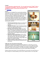
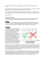
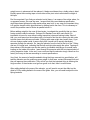
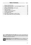
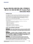
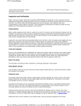
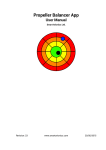
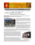
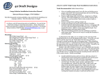
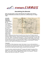
Design | Manufacture | Database | Galleries | Issues | Competitions | Projects | Files | Records | Stories | Links | Yahoo Group
Assembling the Elevator
Note: This page applies to early model Standard Cirrus gliders with T-fitting(1)
Elevator attachment mechanisms, as pictured here. (Click the image for a larger
view.)
Assembly
Procedure
(Flight and
Service Manual,
pg. 19)
It is advisable to
mount the Elevator
by one person
only. Lock the trim
in a front position
first. Put the
Elevator onto the
top of the vertical
tail plane with the
nose about 45
degrees down.
Keep it in this
position, holding it with the left hand. Insert the hook of the push rod(4) between the ball
bearings of fitting(3) and push it forward. Drop the trailing edge of the Elevator until the lower
end of the T-fitting(1) is sitting on the locking bolt(8). Push the locking handle(9) forward, using
a bar of about 8 to 10 mm, 3/8" dia. The plane drops when moving it slightly forward. Insert
the two short pins on fitting(1) into their bushings on fitting(6) by rocking the plane gently back
and forth. The plane drops again about 5 mm, 3/16". Pull the locking handle(9) fully back,
where it is held in place by two separately acting springs.
Comments
It is important to follow these steps exactly if the elevator is to go on without problems. I
have spent as much as half an hour in the hot sun without success, only to discover that the
trim was all the way back rather than forward. If the control stick is not far enough forward,
the hook will not reach high enough to properly mate with the two ball bearings.
On my ship, when I retract the locking bolt(8), it remains aft, despite the springs pulling
against it. So I usually retract it before setting the Elevator on the fin. In that case, the Tfitting(1) falls in place in one step, rather than first resting on the locking bolt(8) and then
falling in place when the locking bolt(8) is retracted.
Caution!
Your life depends on getting this right! You can easily secure the T-fitting(1) without
engaging the ball bearings. This is extremely dangerous! A Standard Cirrus pilot
was killed on August 10, 2002 for this very reason. See
the NTSB report.
Checks
Every owner of a Standard Cirrus occasionally assembles
the Elevator incorrectly. They know from experience what to
look for. It is very easy to spot the error. They never attach
the Elevator without immediately checking their work. The
risk is for new owners, who have never seen it done
incorrectly and indeed may assume that if it went together, it
must be right. If they are not careful, they will accept any
response of the Elevator to the control stick as evidence that
they got it right. Always perform the following checks to
ensure proper assembly:
•
•
•
•
•
Use the inspection hole (window) in the elevator to
verify that the hook properly mates with the ball
bearings.
Swing the Elevator through its full range of motion. It
should move smoothly, without rattling or the sound
of the hook rubbing inside the faring.
Move the control stick fore and aft, from stop to
stop. Do this slowly and rapidly while watching the
elevator. The elevator should follow every movement
of the control stick smoothly and exactly. It should be
evident that the control linkage is both pushing and
pulling the elevator.
Notice the angle of the Elevator with the control
stick fully aft. The fairing should be fully concealed
within the vertical fin. If the hook is not properly
mated with the ball bearings the leading edge of the
Elevator will not dip far enough.
Perform a positive control check! This will confirm
that the hook is both pushing and pulling the nose of
the Elevator.
A Look Inside (Stefan Melber)
Access Holes
Spar Connection
T-Fitting
A Message from Tom Knauff (26 Aug 2002)
Yesterday, we intentionally incorrectly installed the Elevator on a Std Cirrus. It's not too
difficult to do, however, once installed, it is very obvious it is not correct. When the control
stick is moved back and forth, the push rod makes a lot of noise as it bangs around inside
the Elevator. There is no movement up. The fairing on the bottom, leading edge of the
Elevator is well above the normal position so you can see the bottom of the fairing.
Doing a positive control check, if you hold the Elevator in one position, the control stick can
feel as though it is connected when you pull or push, however, there is a lot of slop when
you switch from pull to push. A slight jiggle cases the elevator push rod to make a lot of
noise.
If your clear vision disc is no longer clear so you can see to inspect the connection, consider
removing the disc and taping over the hole until you replace the disc.
After installing the Elevator correctly, consider painting two thin lines on the rudder to show
the normal travel limits of the elevator. This may become an FAA recommendation as well.
Thomas Knauff
Worst Case Scenario
This scenario is offered to help you recognize your error quickly in the unlikely event that
you improperly attach the Elevator and then fail to perform the required checks.
Disclaimer:
I must plead ignorance of the geometric relationship between the Elevator pivot and the
center of lift, as well as the aerodynamics needed for a proper analysis. So, the following
analysis may be flawed. But I am confident that you will agree with the main points.
The Problem:
The T-fitting(1) is secured by the locking
bolt(8), but the hook does not engage
the lower bearing. So the hook is free
to move about laterally. The lower
bearing rests on top of the hook
pushing it against the forward edge of
the bearing access slot, and the front of
the Elevator is abnormally high.
Perhaps the hook engaged the edge of
the access slot, so that there is some
control in both directions. The front
edge of the access slot is not strong
stuff, and the fiberglass will break when
aerodynamic forces on the Elevator jam
the hook between it and the bearings.
Correc
t and Incorrect Assembly
Click for larger image.
Drawing by Bob Kuykendall.
With the control stick fully forward, the front of the Elevator will be forced up; however, if the
access slot is not hung up on the hook, it is free to go still higher since the stop is located at
the control stick, not in the Elevator. On the other hand, with the stick fully aft, the hook will
be at its lowest position and the Elevator, if the edge of the access slot is not hooked, will be
free to swing down as far as the hook allows.
If the glider is in motion, you can expect the Elevator to flip from one limit or the other. Either
the leading edge will be up (pitching the glider down), or it will be down (either pitching the
glider up or reducing the downward pitching, to some degree, depending on the position of
the stick and the damage to the bearing access slot). This is not a pretty picture!
The Ground Roll:
For a normal launch, the trim will be in a forward position, anticipating the airspeed on tow.
The stick will be somewhat forward or will be moved forward, as airspeed builds, to lift the
tail, giving the ship a proper attitude for a gentle lift off. This action forces the front of the
Elevator high, although it is free to move yet higher. So, the tail will lift off as expected, but
you may be surprised that it stays high even though you have pulled the stick back to a
center position. When the tail stays up, you continue to pull the stick aft. ... Airspeed is
building as are forces acting on the Elevator.
The Decision Point:
You're getting concerned (or annoyed) because you have enough airspeed to lift off, but the
tail is too high still and it isn't responding even with the stick farther aft than necessary.
Perhaps the tow plane has lifted off and you're still on the ground. At this point you are
well behind the curve! Already, you should have seen the signs, pulled the release,
pulled the airbrakes, and squeezed the wheel brake for all it's worth! But, you're not
inclined to panic, nothing bad is happening and instinct urges you to pull the stick all the
way...and you do. Now the push rod(4) is fully down and the Elevator has maximum
freedom.
The Launch:
Now the tail wheel runs over a bump, and the Elevator decides to swing the other way, all
the way the other way! The leading edge flips down as far as the stick allows, considering
the rigging error. And with all that airspeed, the glider shoots up into the sky. Now you
panic! Now you shove the stick all the way forward, forcing the front of the elevator up. If
you were quick enough, the glider heels over, and you pull back on the stick to control your
rate of descent. But the elevator stays up and the glider noses down too steeply. If you're
lucky, on the way down, the elevator decides to flip, leading-edge down, and recovers from
the dive. By then, however, you've pulled the stick all the way back again, so the the
Elevator swings too far and you go shooting up into the sky again. ... You get the idea. In all
the panic, you completely forget to pull the release.
The Crash:
On the first or second up swing (if you get that far) the rope breaks because it has a proper
weak link. Perhaps this saves the tow pilot and tug, since he didn't have time to pull his
release because everything happened so quickly. Now the glider has an extremely nose
high attitude and you are forcing it down with full forward stick, shoving the front of the
Elevator up. It may heel over, or it stall and fall nose down, or it may tail slide. Most likely
you will hit the ground at a very steep nose-down attitude, perhaps past vertical. ... The rest
you can imagine.
The Moral:
•
•
•
•
Love your wife!
Install the Elevator correctly!
Perform the assembly checks and a positive control check!
Release at the very first sign of something unexpected! Don't think! Don't wait for
trouble! Just release!
Conclusions
•
•
•
The Standard Cirrus is a good bird. Nearly seven hundred have been flying for over
thirty years with an excellent safety record.
Even modern gliders sometimes launch with improperly attached tail assemblies.
The Standard Cirrus is no worse than others in this regard.
The elevator is the most critical control on your aircraft. Get it wrong and your
chance of survival after lift off is nil.
Jim Hendrix
Balancing the Elevator
Pages 28 and 29 of the Flight and Service Manual give specifications for weight and balance
of control surfaces. The manual specifies a maximum weight for the elevator of 7.1 kg
(15.65 lb). The maximum hinge moment is 0.143 m*kg (1.03 ft*lb).
Weighing the elevator is easy. The maximum weight includes the T-fitting, so you can
merely place the whole assembly on a scale an take the reading.
The T-fitting design makes balancing this elevator easy too. All you need to do is fix the
stem of the T-fitting in a vice to hold the elevator horizontal, with complete freedom of
movement. Take care not to over tighten the vice with consequent damage to the T-fitting.
Cloth cushioning in the vice jaws is a good idea. Mount the elevator so that it's aft edge is
over a work surface where you can place a small, accurate scale, like a postage scale. For
better accuracy, use a scale with the smallest range possible.
Zero the scale, then stand a stick or rod on the scale and rest the rear edge of the elevator
on it. The length of the stick should be such that the elevator chord is horizontal. Read the
weight and subtract the weight of the stick. For the hinge moment, multiply this weight times
the moment arm, the distance from the hinge axis to the support point where the elevator
rests on the stick. For better accuracy, the stick may have a pointed end or the elevator may
be supported at it's trailing edge.
To measure the moment arm, you need to find the hinge axis. Since the hinge bearings are
buried within the elevator this is difficult to do. However, Stefan Melber opened up his
elevator and removed the T-fitting, bearings and brackets. He has measured the distance
from the elevator hinge axis to the center of the two locator pins on the T-fitting. This
distance is 27.6 mm (1.087"). So, to get the moment arm, you can measure from the aft
support point to the center of the locator pins on the T-fitting and add 27.6 mm.
The longer the moment arm, the better the accuracy. This is because the down force on the
scale will be less and you can use a more sensitive scale, also, the error in your
measurement of the moment arm will be less significant if the moment arm is longer. One
way to lengthen the moment arm is to tape a beam in the chordwise direction to the elevator
so that it extends aft to say two or three times the normal moment arm. The weight of the
beam will not affect the result if it is balanced over the hinge axis, so you should let it extend
forward just as far as it extends aft of the hinge axis. Furthermore, if the beam is light
weight, errors in placement will be reduced. A balsa wood beam from a hobby shop is ideal.
Equally space the mounting tape on both sides of the pivot axis to eliminate the weight of
the tape.
Don't be surprised if you find your elevator too tail heavy. I am aware of two ships where, for
no apparent reason, this was the case. I suspect that the current balance specification
might have been tightened up after earlier ships were built. In any case, the important thing
is to get the elevator within specifications by adding lead to the nose. This is necessary to
control the possible onset of flutter at speeds below Vne.
Before adding weight to the nose of the elevator, investigate the possibility that you have
foreign matter inside the elevator. Perhaps Dirt Daubers have built nests inside. It's
impossible to know for sure without cutting inspection holes and looking inside. Short of
that, you could pound on the surfaces with your hand to flex the skin causing the dirt nests
to break loose and rattle around inside. Flushing with water might also loosen them. If you
do have foreign matter inside, it seems likely that it would not be equally distributed
spanwise through the elevator. So, hang the elevator from the hole at the tip of the T-fitting
and see if it hangs level, indicating that the left and right sides weigh the same. Tapping on
the surfaces of the elevator can also be used to give audible indications of unusual mass
loading on the inside of the skins. I went through this exercise with #60 but stopped short of
cutting inspection holes. In the end, I was convinced that the elevator simply came from the
factory too heavy at the rear according to current specifications.
Very likely, the amount of weight needed to bring the hinge moment into specification, will
take the elevator over the maximum gross weight. In that case, contact Schempp-Hirth and
they will approve the modification. They will tell you that the important thing is reducing the
hinge moment. If the elevator must go over gross to do that, then it must be done.
After adding ballast to the nose of the elevator, you will need to correct the effect on the
glider's CG by adding ballast to the nose of the glider. Also, you will need to adjust the trim
spring tensions.