1
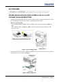
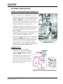
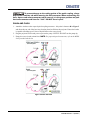
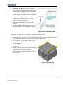
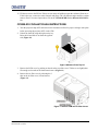
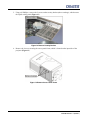
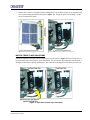
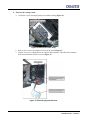
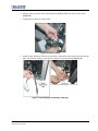
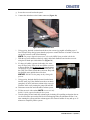
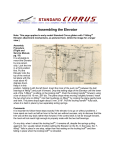
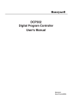
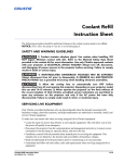
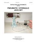
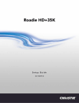
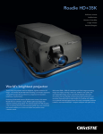
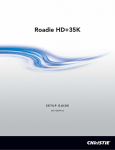
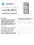
Roadie 25K/HD+30K/HD+35K, CP2000-S/SB/-h/-i/-X/-XB/-M/-MR/-ZX Coolant Flush
Instruction Sheet
INTRODUCTION
If using Jeffcool E105 coolant in your system, it is recommended the coolant system is flushed out
every 32,000 hours (or earlier if needed) and refilled with clean coolant. Using other coolants is not
recommended and may increase the frequency that the system must be flushed. This procedure is
extremely important to prevent overheating and sudden operation failure. For coolant refill
instructions, refer to the Coolant Refill Instruction Sheet (P/N: 020-100686-xx). For additional
information refer to the specific projector Service Manual.
Use the following instructions when performing routine maintenance on the coolant system in the
following projectors:
•
•
•
•
•
•
•
Roadie 25K/HD+30K/HD+35K (P/N: 38-DCP500-xx/113-002101-xx/113-105107-xx)
CP2000-S/SB (P/N: 38-DCP301-xx/106-004101-xx)
CP2000-h (P/N: 38-DCP301-xx)
CP2000-i (P/N: 38-DCP301-xx)
CP2000-X/XB (P/N: 38-DCP301-xx/101-001101-xx)
CP2000-M/MR (P/N: 119-001101-xx/119-002103-xx)
CP2000-ZX (P/N: 116-001101-01/03, 116-001113-xx/116-001124-xx)
SAFETY AND WARNING GUIDELINES
Coolant contains ethylene glycol. Use caution when handling. DO NOT
ingest. Minimize contact with skin. Refer to the Material Safety Data Sheet provided in
the coolant kit for more information. Use only Christie approved coolants with your
projector.
1) QUALIFIED SERVICE TECHNICIANS REQUIRED! All module
replacement procedures must be performed by qualified service technicians. 2) NONINSULATED DANGEROUS VOLTAGES MAY BE EXPOSED! Always disconnect from AC
prior to disassembly. 3) OBSERVE ALL ELECTROSTATIC PRECAUTIONS! Use a
grounded wrist strap when handling electronic assemblies.
1) HIGH VOLTAGES MAY BE EXPOSED! Always power down and
disconnect power sources prior to servicing. Once the projector is powered down,
allow the cooling fans to automatically turn OFF before disconnecting from AC and
opening the projector. Depending on your projector model this can take 10-15 minutes.
2) Never operate the projector (or the fans) without all the covers installed.
Roadie 25K/HD+30K/HD+35K, CP2000-S/-SB/-h/-i/-X/-XB/-M/-MR/-ZX Coolant Flush Instruction Sheet
020-100179-03 Rev. 1 (03-2011)
1 of 12
KITS REQUIRED
• #003-001667-xx Coolant Drain Kit (1m tubing with quick coupling and gear clamp specific for each model, instructions)
• #003-001837-xx Coolant Refill Kit (includes JeffCool E105 jug of coolant, refill bottle, funnel, MSDS sheet)
ROADIE 25K/HD+30K/HD+35K & CP2000-S/-SD/-H/-I/-X/-XB
COOLANT FLUSH INSTRUCTIONS
1. Turn the projector lamp OFF and wait at least 10 minutes to allow for proper cooling to take place
before powering the projector OFF via the Control Display Panel (CDP).
2. Remove the projector lid:
• On the Roadie 25K/HD+30K/HD+35K or CP2000-X/-XB, open the igniter door (Figure 1,
left).
• On a CP2000-S/-SB/-i/-h (Figure 1, right), open the non-operator side pedestal door, and
advance to Step 3.
Figure 1 Access Cooling System
3. On the CP2000-X/-XB or Roadie 25K/HD+30K/HD+35K, remove the center (8 screws) and front
belly pans (4 screws), as shown in Figure 2.
Figure 2 Remove Belly Pans
2 of 12
Roadie 25K/HD+30K/HD+35K, CP2000-S/-SB/-h/-i/-X/-XB/-M/-MR/-ZX Coolant Flush Instruction Sheet
020-100179-03 Rev. 1 (03-2011)
DISCONNECT RESERVOIR HOSE
CP2000-X/-XB OR ROADIE 25K/HD+30K/HD+35K
Disconnect the reservoir hose ONLY at the quick coupling
connector in the light engine area (Figure 3), as follows:
1. Follow the route of the reservoir hose directly from the
reservoir to the hose link cover in the light engine area
(Figure 3). NOTE: Reservoir hose quick coupling
connection location may be different in the various
projector models. Ensure that you disconnect the reservoir hose and NOT the heat exchanger hose.
2. Standing on the lamp side of the projector, reach
between the cardcage and the hose link cover and into
the finger access hole (quick release access label,
shown in Figure 3).
3. Depress the appropriate connector release tab, pushing
toward the front of the projector, to release the
reservoir hose quick coupling connector.
4. Gently pull the reservoir hose free at the underside of
the projector. NOTES: 1) For better access on the
CP2000-X/-XB and Roadie 25K/HD+30K/HD+35K,
you may want to remove the small hose link cover
shown in Figure 3 (4 screws) to increase visibility,
particularly for re-connection. 2) Have a rag handy as
you disconnect the hose to catch any drips.
Figure 3 Disconnect Reservoir Hose
(CP2000-X/-XB shown)
CP2000-S/-SB/-H/-I
1. Within the pedestal (near the front),
release the reservoir hose quick coupling
connector at the top edge of the pedestal
(Figure 4). NOTE: The physical location
of this quick coupling connector may vary
from model-to-model and from unit-tounit – i.e., the reservoir may connect near
the lamp side, or it may connect near the
igniter side. Make sure to disconnect the
reservoir hose in all cases.
Figure 4 Hose Connections in CP2000-S/-SB/-h/-i
Roadie 25K/HD+30K/HD+35K, CP2000-S/-SB/-h/-i/-X/-XB/-M/-MR/-ZX Coolant Flush Instruction Sheet
020-100179-03 Rev. 1 (03-2011)
3 of 12
To prevent damage to the sealing gasket of the quick coupling, always
depress the connector tab while removing the hose connector. When reconnecting the
hose, depress and release connector tab to ensure it is in the proper position and push
hose onto connector and listen for “click”. DO NOT force in place.
DRAIN AND FLUSH
1. Attach the 1m hose to the exposed quick coupling connector – this point is shown as A in Figure 5
and direct the raw end of the hose into a bucket placed well below the projector. Ensure the bucket
is capable of holding up to 2 liters of liquid. Remove the reservoir cap.
2. Plug the projector back in and power-up to run the pump. NOTICE: DO NOT run the pump dry.
3. Empty the reservoir and coolant lines. NOTE: For proper disposal instructions, refer to the MSDS
sheet provided with the kit.
Figure 5 Drain and Flush
4 of 12
Roadie 25K/HD+30K/HD+35K, CP2000-S/-SB/-h/-i/-X/-XB/-M/-MR/-ZX Coolant Flush Instruction Sheet
020-100179-03 Rev. 1 (03-2011)
4. Fully Flush and Rinse: As the system begins to
empty, add plain distilled water to thoroughly flush
and rinse all hoses (Figure 6). Watch carefully for
air locks (including under the projector) and make
sure the pump does not run dry, as this can damage
the pump. Draining will happen very quickly.
5. Continue adding distilled water to the reservoir
until the system appears to be free of coolant
residue and waster liquid is clear.
6. Drain fully and immediately power down the
projector.
7. To drain and flush the disconnected reservoir line,
add water to the reservoir and push on the end of
the quick coupling connector until the line is clean.
Figure 6 Flush with Distilled Water
CP2000-M/MR COOLANT FLUSH INSTRUCTIONS
1. Turn the projector lamp OFF and wait at least 10 minutes to allow for proper cooling to take place
before powering the projector OFF via the Control Display Panel (CDP).
2. Use a #2 Phillips™ to loosen the 7 captive screws
securing the top lid to the projector
housing (Figure 7).
3. Unlock the rear access door using the low
security key.
4. Lift the lid up from the rear of the projector and pull it
away from the two tabs on the front skin.
5. When installing, align the front two tabs and reverse
the above steps.
Figure 7 Remove Top Lid
Roadie 25K/HD+30K/HD+35K, CP2000-S/-SB/-h/-i/-X/-XB/-M/-MR/-ZX Coolant Flush Instruction Sheet
020-100179-03 Rev. 1 (03-2011)
5 of 12
6. Remove access panel:
a. Use a #2 Phillips™ to remove the 2 screws at
each corner of the skin (Figure 8).
b. Use a 4mm hex key to remove the 5 socket
head cap screws along the bottom edge of
the skin (Figure 8).
c. Pull the skin forward and out.
d. Reverse the above steps to re-install the
skin. NOTES: 1) Ensure the front and rear
corners interlock before reinstalling the
screws. 2) To remove the access panel separately loosen the two captive screws securing it to the skin.
7. Disconnect the Blue DMD hose at the reservoir
end. Keep the hose to the Red DMD intact.
Figure 8 Remove Access Panel
8. Attach the coolant hose to the spare length of
hose provided in the flush kit. NOTE: You may need to swap out the coupling on the hose supplied
to fit with the connector of the Blue DMD hose.
9. Insert the open end of the coolant hose into a waste jug capable of holding up to 2 liters of liquid.
Position the jug lower than the reservoir to allow gravity to drain the liquid from the cooling
system (Figure 9).
10. Before the reservoir completely
empties, raise the waste jug and hose to
Reservoir
stop draining. Set it down on a
surface higher than the reservoir.
To Blue DMD
11. Using the fill bottle provided, slowly add
distilled water into the reservoir until it
reaches the fill line.
12. In short intervals, turn the pump ON and To Red DMD
Attach reservoir hose
OFF by pressing PWR ON and PWR
to hose from kit
OFF on the CDP. This is done to flush the
system out. Keep adding distilled water
until the hoses run clear. NOTICE! DO
NOT let the reservoir run dry during this
Gravity will
process.
drain the line
13. With the coolant hose still in the waste
jug, lower the jug as before to drain the
distilled water out of the coolant system.
Waste Jug
If the distilled water does not drain
Figure 9 Drain Coolant
completely by itself, add some coolant to
the reservoir and flush the water out by
turning the pump ON and OFF.
14. With the coolant system now flushed out, reconnect the hose to the Blue DMD and add coolant to
the reservoir using the fill bottle provided in the kit. NOTE: For proper disposal instructions,
refer to the MSDS sheet provided with the kit.
6 of 12
Roadie 25K/HD+30K/HD+35K, CP2000-S/-SB/-h/-i/-X/-XB/-M/-MR/-ZX Coolant Flush Instruction Sheet
020-100179-03 Rev. 1 (03-2011)
15. Fill the reservoir to the fill line. If there are too many air bubbles present the coolant will not move.
If this is the case, remove the entire fan pack and pump. Tilt it at different angles until the coolant
starts to flow. For removal procedures refer to the CP2000-M/MR Service Manual (020-100124xx).
CP2000-ZX COOLANT FLUSH INSTRUCTIONS
1. Turn the projector lamp OFF and wait at least 10 minutes to allow for proper cooling to take place
before powering the projector OFF via the CDP.
2. Unlock the front lid using the high security key.
Raise the lid and slide it out from the opposite
side (Figure 10).
Figure 10 Remove Front Top Lid
3. Remove the PCM cover by pushing on the tab at the top of the cover. Tilt the cover slightly then
lift enough to clear tabs at the bottom and remove (Figure 11).
4. Remove the air filter cover by releasing the 2
tabs on the air filter cover, lift and remove
(Figure 11).
Figure 11 Remove PCM and Air Filter Covers
Roadie 25K/HD+30K/HD+35K, CP2000-S/-SB/-h/-i/-X/-XB/-M/-MR/-ZX Coolant Flush Instruction Sheet
020-100179-03 Rev. 1 (03-2011)
7 of 12
5. Using a #2 Phillips™, remove the 2 screws on the security bracket (above cardcage), which secures
the liquid cooling panel (Figure 12).
Figure 12 Remove Security Bracket
6. Remove the 4 screws securing the access panel frame, which is located on the input side of the
projector (Figure 13).
Figure 13 Remove Access Panel Frame
8 of 12
Roadie 25K/HD+30K/HD+35K, CP2000-S/-SB/-h/-i/-X/-XB/-M/-MR/-ZX Coolant Flush Instruction Sheet
020-100179-03 Rev. 1 (03-2011)
7. Remove the 5 screws securing the liquid cooling panel. Four of these screens are on the panel and
one is located along the bottom of the panel (Figure 14) . Swing the panel out and hang it on the
screws located on the frame.
Figure 14 Liquid Cooling Panel Overview
NOTICE! TRIPLE FLASH PROJECTORS
Determine whether or not your unit is a triple flash projector. Refer to Figure 15. If your projector is a
pre-triple flash unit it will not have quick disconnects. You will need to disconnect the hose from the tfitting and connect the required draining hose, provided. Drain the liquid from the hose you removed.
Figure 15 Triple Flash and Pre-Triple Flash Units
Roadie 25K/HD+30K/HD+35K, CP2000-S/-SB/-h/-i/-X/-XB/-M/-MR/-ZX Coolant Flush Instruction Sheet
020-100179-03 Rev. 1 (03-2011)
9 of 12
8. Flush out the cooling system.
a. Unclip the 2 clips securing the pump to its rubber housing (Figure 16).
Figure 16 Remove Reservoir Pump
b. Remove the 2 screws securing the reservoir to the panel (Figure 17).
c. Flip the reservoir so it hangs below the t-intersection connector. This allows the coolant to
drain around the back into the reservoir (Figure 17).
Figure 17 ZX Cooling System Overview
10 of 12
Roadie 25K/HD+30K/HD+35K, CP2000-S/-SB/-h/-i/-X/-XB/-M/-MR/-ZX Coolant Flush Instruction Sheet
020-100179-03 Rev. 1 (03-2011)
d. Using needle nose pliers remove the clamp from the Blue DMD side of the t-intersection
(Figure 18).
e. Unplug the hose from the t-intersection.
Figure 18 Remove Clamp
f. Install a quick disconnect line into one end of the t-intersection and a female connector into the
other end. Slide the clamp over the female connector to prevent leaking (Figure 19).
Figure 19 Install Stopper and Female Connector
Roadie 25K/HD+30K/HD+35K, CP2000-S/-SB/-h/-i/-X/-XB/-M/-MR/-ZX Coolant Flush Instruction Sheet
020-100179-03 Rev. 1 (03-2011)
11 of 12
g. Secure the reservoir back to the panel.
h. Connect the drain hose to the female connector (Figure 20).
Figure 20 Connect Drain Hose
i.
j.
k.
l.
m.
n.
o.
12 of 12
Using gravity, drain the coolant from the hoses into a waste jug capable of holding up to 2
liters of liquid. Keep the jug lower than the projector to control the flow of coolant. Loosen the
cap on the reservoir to aid in fluid draining.
NOTE: For proper disposal instructions, refer to the MSDS sheet provided with the kit.
With the reservoir and hoses relatively empty, add a little distilled water into the reservoir
using the fill bottle provided with the kit (Figure 21).
If a large air bubble is present in the tubes, the water
may not flow freely. If this is the case fill the reservoir
to the top fill line and in short intervals, turn the pump
ON and OFF by pressing PWR ON and PWR OFF on
the CDP. This is done to flush the system out. Keep adding distilled water until the hoses run clear.
NOTICE! DO NOT let the pump run dry during this
process.
Using gravity, drain the distilled water from the hoses
into the waste jug. If the distilled water does not drain
completely by itself, add some coolant to the reservoir.
Flush the water out by turning the pump ON and OFF.
Disconnect waste line and reassemble coolant system.
Figure 21 Fill Reservoir
Fill the reservoir with coolant. NOTE: A reservoir only
holds 1/2 of the required coolant for the system.
Turn the pump ON and watch the coolant begin circulating. Keep adding coolant into the reservoir as needed to prevent the fluid level from dropping below the minimum fill line. Continue running the system until the coolant appears free from air bubbles. It may take up to 15
minutes to completely fill the system.
Roadie 25K/HD+30K/HD+35K, CP2000-S/-SB/-h/-i/-X/-XB/-M/-MR/-ZX Coolant Flush Instruction Sheet
020-100179-03 Rev. 1 (03-2011)