1
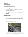
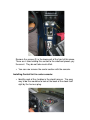
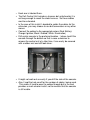
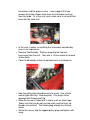
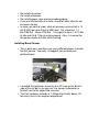
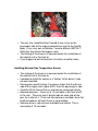
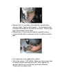
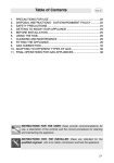
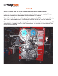
Gauge install for Subaru
Impreza WRX STi
NOTE: Perform this install at your own risk. I am providing this as a
guide so that you may have some assistance in performing an install.
I am in no way responsible should you mess anything up or should
something go wrong.
About gauges in general:
In my experience, I have found that most Japanese manufacturers
(Defi, Blitz, Greddy, SARD) make gauges that are FAR superior in
quality than American manufacturers (Autometer). The hardware
supplied with the JDM kits are of much higher quality and are usually
designed to provide a much longer life span.
Installation:
This installation will cover the wiring of Defi BF series gauges. Some
of the steps used in this install are specific for these gauges and will
not apply for other types of gauges.
Tools needed:
•
•
•
•
•
•
•
•
8-mm, 10-mm, 12-mm, 13-mm, 14-mm, 17-mm sockets
8-mm, 10-mm, 12-mm, 13-mm, 14-mm, 15-mm, 17-mm open
end Wrenches
17-mm Crow’s foot.
Drill
Various drill bits
1/8 ” NPT Tap for EGT bung
Dremel (for making holes in plastic as well as the heat shield)
Screwdrivers: Phillips and flat head (its nice to have a longer flathead
sometimes too)
•
•
•
Various needle nose pliers and wire strippers/crimpers
Soldering gun (If you plan to solder the wiring like I did)
Various additional wiring if you plan to extend some cables.
This install covers:
Control Unit II
Defi BF Boost Gauge
Defi BF Oil Temperature Gauge
Defi BF Exhaust Gas Temperature Gauge
Defi Pod (GDA/GDB Impreza chassis)
Before the fun begins…
• If necessary, write down all the radio stations saved in the
memory of the radio presets.
• Using a 10mm wrench/socket, remove negative battery terminal
from battery.
Removing clock pod.
• This takes a great amount of force, so come prepared. Start by
pulling the area closest to the windshield and then unclip the
rear.
• Remove harness plug from clock unit.
• If you look behind the clock, you will notice that the appropriate
wires have been conveniently labeled so that you don’t have to
spend extra time looking around for a multi-tester and/or other
threads on various sites or how-tos.
• There are four wires in the clock harness. They will all be used.
Battery, Ground, Illumination, Ignition.
Installing Defi Pod
• This also takes some doing. Many people have broken a tab
when installing this unit. In all the units that I’ve installed, I
always start by inserting the front of the pod first and then work
my way around to the back. Just push down pretty hard on all
the edges until the unit clicks into place.
Removing center section of 2005 WRX/STi (console install)
• Remove the center console from vehicle. First undo the
buttons from the e-brake and the shifter boots.
• Push up on shifter boot surround to lift this part out of the way.
You may choose to remove the harness/light from the ashtray
area.
• Open center console. Using a Phillips screwdriver, remove 2
screws from the front area of the console, and 2 screws from
the bottom of the console itself.
• Remove 2 screws from the front of the center section, on the
sides of where the ashtray used to be.
• You can now remove the top of the center section. Please
make sure to unplug the two harnesses under the DCCD and
mirror controls.
• Remove the cover of the radio HVAC controls. In the 05 STi,
this will require the removal of two screws that hold the bottom
end of the cover. After these have been removed, pry the
cover from the bottom up. The bottom comes off fairly easily,
the top requires more force. Use good judgment to ensure that
you do not damage this piece.
• To remove the bottom of the center section. Remove the screw
in the middle of the section, behind the shifter.
Remove the screws (2) in the lower part of the front of this piece.
There are 4 tabs holding this section to the side/front pieces, pry
these out. They do not take much effort.
• You can now remove the center section with the console.
Installing Control Unit in center console:
• Identify each of the 4 cables in the clock harness. The easy
way to do this would be to look at the back of the clock itself
right by the harness plug.
•
•
•
•
•
Each one is labeled there.
The Defi Control Unit includes a harness but unfortunately it is
not long enough to reach the clock harness. So these cables
must be extended.
In the case of this install, I decided to solder the cables for the
extension, you may choose to use butt connectors or any other
means.
Connect the cables to the appropriate colors (Red: Battery;
Orange: Ignition; Black: Ground; White: Illumination)
Drill center console in the preferred location. I chose to drill the
console through the bottom so that in case a decision to
remove the control unit at a later time, it can easily be covered
with a rubber mat and still look clean.
• It might not work out so easily if you drill the side of the console.
• Also, I kept the hole small for the number of cables being used.
This makes it hard to pass the cables through but in the end,
provides a much cleaner install, not to mention that the console
is still usable.
• At this time, if you haven’t done so already, run all the sensor
harnesses through the firewall. I chose to run them through the
plug by the clutch. Make sure that the wire harness is not in an
area that will interfere with driving duties and what not.
• Run all the necessary harnesses through the hole that you
have drilled out.
• When cables are ready, go ahead and stick on the tape to the
control unit.
• Plug harnesses into the appropriate plugs.
• NOTE: If you are installing Defi BF gauges, use Output 2
for the gauge harness. If installing Link series, use Output
1.
• Stick Control Unit into desired spot.
• Re-install all panels and harnesses in reverse process to what
had been described above.
• Re-connect battery if you are finished with all electrical
installations.
Installing Oil Pressure/Temperature sensor
• The two sensors are different in size and shape, but they can
both be installed in the same manner.
• Remove intercooler. You will need a 12-mm socket, 10-mm
open end wrench, 8-mm socket with extension, and or flat head
screwdriver. Start by removing the lines around the front of the
intercooler and the bypass valve. I also suggest that you
remove the turbo silicone hose from the intercooler and not
from the turbo. Or at the very least, make sure to re-install that
hose into the turbo first.
• In the end, it makes re-installing the intercooler considerably
easy in my experience.
• Remove throttle body. Start by removing the two wire
harnesses from the unit. Then use a 10-mm socket to remove
all four bolts.
• Cover throttle body so that no contaminants are allowed in.
• Now the galley plug should be easy to reach. Use a 8mm
socket-type allen key. Remove plug. This plug is to be
replaced with Subaru part No.
• Wrap the sensor’s thread with a sealer such as teflon tape.
Make sure that you do not use too much and that only the
threads are covered. The factory plug already has thread
sealer.
• Screw the sensor into the tapped galley plug and tighten until
snug.
•
•
•
•
•
Hand screw the new galley plug/sensor into the hole and when
the time comes, use the 17-mm Crow’s foot to tighten the
Galley plug. Tighten to 18.1 ft-lbs, or 25 Nm.
Plug harness to sensor.
Secure harness to preferred areas.
The routing of the harness is covered under the installation of
the control unit in this how-to.
Reinstall throttle body. The service manual recommends that
you use a new throttle body gasket. Your stock gasket will
most likely still be in new condition, but do keep in mind that it
might also not be. Be prepared. Tighten to 5.8 ft-lbs or 8 Nm
Re-install harnesses.
Re-install intercooler.
Re-install bypass valve and surrounding piping.
If you are finished with all installs, check for leaks after the car
has been started.
• In case you want to know, stock oil pressure service limit is 14
psi @ 800 rpm and 43 psi at 5000 rpm. For reference: 14
psi=0.95 Bar 43 psi=2.93 Bar It is typical to have 1.5-2.0 Bar
at idle and 5.6-6.1 Bar at cruising speed. Also, it is normal for
the gauge needle to flutter while cruising.
•
•
•
•
Installing Boost Sensor
• This is quite easy and there are many different places to locate
the Defi sensor. Honestly, I’d suggest you just pick your
preferred spot.
• I installed this particular sensor by the AC lines on the driver’s
side of the car but in my own car, the sensor is placed on a
bracket next to the wiper fluid reservoir.
• The Defi hardware includes a T-fittings that frankly doesn’t fit
too many lines in the engine compartment.
• The only line I could find that it would fit was a line on the
passenger side of the engine compartment next to the throttle
body. In my very own installation, I used a different METAL Tfitting that was tied to the bypass valve.
• The routing of the harness is covered under the installation of
the control unit in this how-to
• If you happen to be finished with all installs, check for leaks.
Installing Exhaust Gas Temperature Sensor
• The routing of the harness is covered under the installation of
the control unit in this how-to
• I decided to install the sensor in a “button” of the driver’s side
exhaust manifold.
• During more recent testing, it has been shown that the driver’s
side of the engine runs higher EGTs than the passenger’s side.
• Carefully lift the front of the car and secure using jack-stands.
• Remove belly pan. There are 3 12-mm bolts in the front and 2
in the rear. There are also 2 plastic tabs on each side of the
pan, for a total of 4. There are tab removers available, but a flat
head screwdriver will work if one is not available.
• Remove driver’s side exhaust manifold heat shield. This is
secured by 3 12-mm bolts.
• Remove the 2 14-mm bolts in that hold the manifold to the
crossover pipe. Hold on to that gasket. You will need at least
one open end wrench for this, but two are useful. Ratchet type
open end wrenches are the best.
• Remove the 3 14-mm nuts that hold the manifold in place.
• Locate the little button in between the No. 2 and No.4 exhaust
pipe.
• Drill a pilot hole in the middle of the “button”.
• Drill a hole using a 11/32” drill bit. Make sure to use some type
of lubricant to cool and help out the bit. Also, regulate the
speed so that you can cut into the metal more efficiently.
Faster really isn’t better here.
• Start to tap your thread using the 1/8” NPT tap. Get some help
for this as it requires some incredible amount of force. It is not
typically recommended to back out of the thread very often
when using a NPT tap.
• And when you think you have gone far enough and hard
enough, back it out, clean the threads, and go again a little
harder until it REALLY is impossible.
• Clean the threads and the interior of the manifold to remove
metal shavings.
• Install the fitting. Use discretion when torquing it down.
• If you plan on re-using the heat shield, do not install the sensor
just yet.
• Mark the heat shield in the appropriate location and use either a
HUGE bit (bigger than 3/8”) or use a dremel to obtain the
desired size.
• Install the manifold back to the engine and crossover pipe.
Don’t forget the gasket!
• Install heat shield.
• Install sensor. Do not over-tighten.
• Plug sensor harness.
• The routing of the harness is covered under the installation of
the control unit in this how-to
• When starting the car, you might experience some smoke due
to the lubricant used during the drilling process. Other than
that, check for leaks.