1
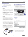
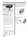
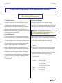
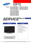
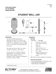
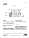
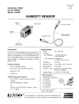
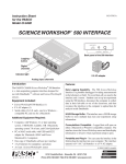
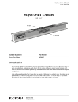
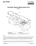
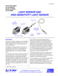
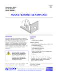
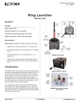
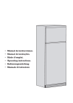
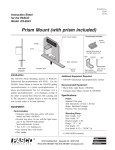
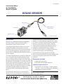
012-06296B Instruction Sheet for the PASCO Model CI-6506B SOUND SENSOR DIN connector interface cable with DIN connectors Sound Sensor 6B 50 -6 CI D UN R SONSO SE aperture for sensor to computer interface Introduction The PASCO CI-6506B Sound Sensor is designed to be used with a PASCO computer interface to make measurements of relative intensity of sound. The sensing element of the Sound Sensor is an electret condenser microphone, which consists of an electret membrane, metal electrode, and field effect transistor that are in an efficient configuration yielding superior signalto-noise ratios (>60 dB) and excellent frequency response (20 to 16,000 Hz). with the Sound Sensor: the Oscilloscope allows the student to view the Sound Sensor output directly, and the FFT function will transform the time domain signal from the sensor to a frequency domain display. These two functions allow the student to investigate the frequency composition of sound produced by the human voice, a tuning fork, or loud speaker driven by a complex waveform such as a square wave. Both the Oscilloscope and FFT functions may be used simultaneously. The Sound Sensor can be plugged directly into any PASCO computer interface box or can be connected to the interface box using the supplied cable with 8-pin DIN connectors. Two stages of amplification are provided to condition the low-level signal from the microphone for input into the ScienceWorkshop computer interface. The output from the sensor is bipolar and ranges between ±10 volts. When the sensitivity is raised to high in ScienceWorkshop (700 interface only), the Sound Sensor detects voltage levels as low as 0.0005 volts, corresponding to sound levels that are barely audible to the human ear. Sound levels ranging from classroom background noise (45 dB) to levels exceeding 100 dB are easily detected with the Sound Sensor. Additional Equipment Required: • Any PASCO ScienceWorkshop computer interface (300, 500, or 700 series for Macintosh or Windows) or the 6500 series interface for DOS The Oscilloscope and Fast Fourier Transform (FFT) functions of Science Workshop may be used effectively © 1997 PASCO scientific Author: Sunny Bishop Equipment Included: • sound sensor in sensor box • 6-foot cable with 8-pin DIN connectors Sound Sensor 012-06296B Additional Equipment Suggested: • Tuning Forks (SE-9325 or SE-9326) • Organ Pipe with Sliding Piston (SF-9328) • Acoustics Demonstration Disk (SF-9410) Figure 1. Connecting the Sound Sensor into the computer interface. ➁ Open the Experiment Setup window in Setup Procedure ➀ Connect the Sound Sensor and any analog channel on ScienceWorkshop. Click and drag the analog plug icon to the analog channel icon that matches the analog port you are using for the Sound Sensor (Figure 2). the computer interface box with interface cable (Figure 1A), or insert the DIN plug of the Sound Sensor into the jack of any analog channel on the computer interface box (Figure 1B). The sound level, which is measured in decibels can be calculated from amplitude of the voltage. The formula is. B = 10 * log(A^2/A(0)^2) Where A is the amplitude of the voltage and A(0) is the theoretical amplitude for a sound level of 0 dB. At a frequency of 440 Hz, A(0) = 10 ^ -4 volts approximately. To have Data Studio perform this calculation, click on th Calculate button and type the following equation: sound level = 10*log(amplitude (10,10,.001, v^2)/(10^8). In the Variables section of the Calculator, define v as Voltage, Ch A. This equation is optimized for a sine wave at 440 Hz, so you may need to adjust the third argument of the amplitude function (it should be about equal to the period of the wave). The value of 10^-4 volts is also optimized for 440 Hz. Since the response of the sound sensor varies with frequency, you may want to calibrate the equation for a different frequency. To do so, you would need a stand-alone sound level meter. Measure the sound level of as sound (B) with the meter, and the voltage amplitude (A) with the sound sensor. Use these values to solve for A(0) in the first equation above. ScienceWorkshop™ ® A s Figure 3. Setting up the Sound Sensor in Science Workshop. ANALOG CHANNELS B n C Interface 2 G 1 (Figure 3). ON DIGITAL CHANNELS GAIN=1,10:ISOLATED GAIN = 1,10: REF TO GND GAIN = 1: REF TO GND B ScienceWorkshop™ 500 P T 6B 50 CI-6 D UN R SONSO SE RES S Plug into any analog channel. O L O 1 ® A s ➃ Open a display window, such as the Oscilloscope ANALOG CHANNELS B n C display, by dragging and dropping the appropriate display icon to the Sound Sensor icon (Figure 4). Interface 2 ON DIGITAL CHANNELS GAIN=1,10:ISOLATED GAIN = 1,10: REF TO GND GAIN = 1: REF TO GND Plug into any analog channel. CI-65 06B T L O G RES S P 500 O ➂ Select "Sound Sensor" from the drop-down menu SESO NSUN ORD A Figure 2. Activating the analog channel in Science Workshop. 2 ® Sound Sensor 012-06296B Mounting on an Experimental Apparatus ➀ Use the 1/4-20 screw connector located on the bottom of the sensor box to secure the Sound Sensor to an experimental apparatus (Figure 6). The alignment hole fits over an alignment pin included on some PASCO apparatuses. alignment hole 1/4-20 screw connector Figure 4. Opening a Display window in ScienceWorkshop. ➄ Additional display windows can be opened by following the procedure in step 4. Calibration and Sensitivity Adjustment in ScienceWorkshop ➀ To open the Sound Sensor's calibration window, Figure 6. Mounting connector and alignment hole. double-click on the Sound Sensor icon in the Experiment Setup window (see Figure 4). DIN Connector Specifications ➁ The sensitivity (gain) of channels A and B of the 300, 1: analog output (+), 0 to 10 V 2: analog output (-), signal ground 6 3: (no connection) 1 4: + 5 V DC power 5: power ground 4 6: +12 VDC power 7: -12 VDC power 8: (no connection) 500, and 700 interfaces in ScienceWorkshop can be adjusted by selecting the appropriate level from the drop-down menu (Figure 5). If the Sound Sensor is producing voltage above 1 V, the sensitivity should be set to Low (1x). If the Sound Sensor is producing voltages between +1 V and -1 V, select Medium (10x). With the ScienceWorkshop 700 interface, the sensitivity can be set to High (100x) if the voltage is very low (between +0.1 V and -0.1 V). Refer to the User's Guide for ScienceWorkshop for more details concerning calibration and adjusting the sensitivity setting. Figure 5. Dialog box for calibrating and adjusting the gain for the Sound Sensor in ScienceWorkshop. ® 3 7 8 3 5 2 Sound Sensor 012-06296B Copyright, Warranty, and Equipment Return Please—Feel free to duplicate this manual subject to the copyright restrictions below. Copyright Notice Equipment Return The PASCO scientific 012-06296A instruction sheet is copyrighted and all rights reserved. However, permission is granted to non-profit educational institutions for reproduction of any part of the Sound Sensor instruction sheet providing the reproductions are used only for their laboratories and are not sold for profit. Reproduction under any other circumstances, without the written consent of PASCO scientific, is prohibited. Should the product have to be returned to PASCO scientific for any reason, notify PASCO scientific by letter, phone, or fax BEFORE returning the product. Upon notification, the return authorization and shipping instructions will be promptly issued. ➤ NOTE: NO EQUIPMENT WILL BE ACCEPTED FOR RETURN WITHOUT AN AUTHORIZATION FROM PASCO. Limited Warranty When returning equipment for repair, the units must be packed properly. Carriers will not accept responsibility for damage caused by improper packing. To be certain the unit will not be damaged in shipment, observe the following rules: PASCO scientific warrants the product to be free from defects in materials and workmanship for a period of one year from the date of shipment to the customer. PASCO will repair or replace, at its option, any part of the product which is deemed to be defective in material or workmanship. The warranty does not cover damage to the product caused by abuse or improper use. Determination of whether a product failure is the result of a manufacturing defect or improper use by the customer shall be made solely by PASCO scientific. Responsibility for the return of equipment for warranty repair belongs to the customer. Equipment must be properly packed to prevent damage and shipped postage or freight prepaid. (Damage caused by improper packing of the equipment for return shipment will not be covered by the warranty.) Shipping costs for returning the equipment after repair will be paid by PASCO scientific. ➀ The packing carton must be strong enough for the item shipped. ➁ Make certain there are at least two inches of packing material between any point on the apparatus and the inside walls of the carton. ➂ Make certain that the packing material can not shift in the box, or become compressed, allowing the instrument come in contact with the edge of the packing carton. 4 Address: PASCO scientific 10101 Foothills Blvd. P.O. Box 619011 Roseville, CA 95678-9011 Phone: (916) 786-3800 FAX: (916) 786-8905 email: [email protected] ®