1
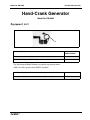
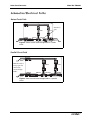
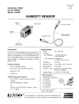
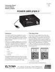
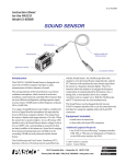
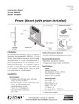
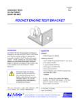
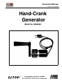
Instruction Manual
Manual No. 012-08330A
Hand-Crank
Generator
Model No. EM-8090
Model No. EM-8090
Table of Contents
Equipment List........................................................... 3
Introduction ............................................................. 4
Suggested Activities .................................................... 4
Demonstrating the Electrical Path through a Series Circuit ..........................................................4
Demonstrating the Electrical Path through a Parallel Circuit ........................................................5
Other Suggested Activities.............................................................................................................5
Schematics: Electrical Pathways....................................... 6
Appendix A: Technical Support ........................................ 7
Appendix B: Copyright and Warranty Information ................... 7
2
®
Model No. EM-8090
Hand-Crank Generator
Hand-Crank Generator
Model No. EM-8090
Equipment List
1
Included Equipment
1. Generator with cables (1), maximum output: 25 Watts, 12 volts
2. Bag, 5” x 9” (1) (not shown above)
Replacement
Model Number*
EM-8090
NSS
*Use Replacement Model Numbers to expedite replacement orders.
NSS= not sold separately from PASCO scientific
Additional Equipment Recommended (for experiments)
Series/Parallel Circuit Board (with five 12-volt light bulbs)
®
EM-8677
3
Hand-Crank Generator
Model No. EM-8090
Introduction
The Hand Crank Generator
(EM-8090) consists of a
permanent magnet DC motor
and is used for demonstrating
how manual work can be
applied to energy conversion.
The generator plugs into the
EM-8677 Series/Parallel
Circuit Board, allowing the
demonstration of both series
and parallel circuit pathways.
Red (+)
lead
Black (-)
lead
Turning
handle
Generator
Cover
Figure 1: Hand-Crank Generator
As a person cranks the handle
on the generator, mechanical energy is transferred to electrical energy
in the circuit and lights the bulb filament(s).
Suggested Activities
Equipment required: You will need the Hand-Crank Generator (EM8090) and a Series/Parallel Circuit Board (EM-8677) to perform the
following suggested activities.
Demonstrating the Electrical Path through a Series Circuit:
1. Connect the black lead to the COMMON port (ground) and the red
lead to the SERIES port of the Series/Parallel Circuit Board (EM8677).
WARNING: To avoid the
risk of shock or damaging
the generator, never
connect the Hand-Crank
Generator to another
power source, disassemble
the generator, use the
generator in or around
water, or try to repair the
generator yourself.
Always keep the plastic
covering over the
generator to protect the
leads from corrosion,
damage, etc. For
assistance with a faulty
generator, see Technical
Support in Appendix A and
the Warranty in Appendix
B.
2. Close Switch 1 (Move the switch handle down into the metal slot.)
Note: Keep Switch 2 open. Switch 2 is used for demonstrating parallel
circuits.
3. Rotate the Hand Crank Generator in the positive direction (shown
by the arrow on label of the generator) at approximately 1 to 2
revolutions per second. Both bulb filaments on the circuit board
will light. (Figure 2 on page 6 shows the electrical pathway.)
4
Note: Rotating the handle
backwards generates a
negative voltage on the
red wire.
®
Model No. EM-8090
Hand-Crank Generator
Demonstrating the Electrical Path through a Parallel Circuit:
1. Insert the black lead into the COMMON port and the red lead into the
PARALLEL port of the Series/Parallel Circuit Board (EM-8677).
2. With Switches 1 and 2 open, rotate the Hand Crank Generator in the positive direction
(shown by the arrow on the label of the generator) at approximately 1 to 2 revolutions per
second. Note what happens.
3. With the leads still connected, close Switch 1 by moving the switch handle down into the
metal slot. Crank the handle. Note what happens.
4. Close both Switch 1 and 2 and crank the handle again. Note what happens. (Figure 3 on
page 6 shows the electrical pathway.)
Other Suggested Activities
a) Plug in two Hand-Crank Generators (using stacked banana plugs) into the EM-8677
Series/Parallel Circuit Board. Have one student rotate the handle of the first generator
forwards (according to the direction arrow on the generator label) and a second student rotate
the handle of the second generator forwards and note what happens. Then have the first
student rotate the handle forwards and the second student rotate the handle backwards and
note what happens.
b) Obtain two Hand-Crank Generators and lay them on the table. Connect the Generators to
each other (through the openings in the back of the banana plugs). Ask a student to crank the
handle of the second generator and note what happens.
®
5
Hand-Crank Generator
Model No. EM-8090
Schematics/Electrical Paths
Series Circuit Path
PARALLEL
BULB 1
COMMON
SWITCH 1
BULB 2
SWITCH 2
Switch 2 is
open.
SERIES
Figure 2: Path of current travel through bulbs in a series
circuit.
Parallel Circuit Path
PARALLEL
Note: If switch 2
is kept open, the
current only
travels through
bulb 1.
BULB 1
COMMON
SWITCH 1
SWITCH 2
BULB 2
SERIES
Figure 3: Path of current travel through bulbs in a parallel
circuit
6
®
Model No. EM-8090
Hand-Crank Generator
Appendix A: Technical Support
For assistance with the EM-8090 Hand Crank Generator or any other
PASCO products, contact PASCO as follows:
Address: PASCO scientific
10101 Foothills Blvd.
Roseville, CA 95747-7100
Phone:
(916) 786-3800
FAX:
(916) 786-3292
Web:
www.pasco.com
Email:
[email protected]
Appendix B:
Copyright and Warranty
Copyright Information
The PASCO scientific 012-08330A Hand Crank Generator Manual is copyrighted and all
rights reserved. However, permission is granted to non-profit educational institutions for
reproduction of any part of the 012-08330A Hand Crank Generator Manual, providing the
reproductions are used only for their laboratories and are not sold for profit. Reproduction
under any other circumstances, without the written consent of PASCO scientific, is
prohibited.
Limited Warranty
PASCO scientific warrants the product to be free from defects in materials and workmanship
for a period of one year from the date of shipment to the customer. PASCO will repair or
replace, at its option, any part of the product which is deemed to be defective in material or
workmanship. The warranty does not cover damage to the product caused by abuse or
improper use. Determination of whether a product failure is the result of a manufacturing
defect or improper use by the customer shall be made solely by PASCO scientific.
Responsibility for the return of equipment for warranty repair belongs to the customer.
Equipment must be properly packed to prevent damage and shipped postage or freight
prepaid. (Damage caused by improper packing of the equipment for return shipment will not
be covered by the warranty.) Shipping costs for returning the equipment after repair will be
paid by PASCO scientific.
®
7