1
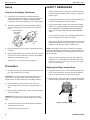
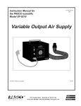
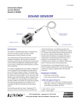
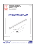
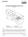
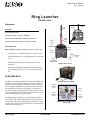
Instruction Sheet
012-13681A
Ring Launcher
EM-8661-220V
Equipment
DISCONNECT INPUT POWER
BERFORE REPLACING FUSE
DO NOT REMOVE COVER REFER
SERVICING TO QUALIFIED PERSONNEL.
Aluminum RIngs (2), 2.5 cm diameter
TO AVIOD ELECTRIC SHOCK THE POWER
CORD GROUNDING CONDUCTOR MUST BE
CONNECTED TO GROUND.
Ring Launcher-220V
FOR CONTINUED FIRE
PROTECTION. REPLACE
ONLY WITH 8A, 250V,
TYPE F FUSE,
(PER IEC 127-2/III)
Included
Rear
view
Rod
Clamp
Iron
Rod
RISK OF ELECTRIC SHOCK
DO NOT OPEN
Copper
Wire
Coil
Universal Grounded Input Adapter (not shown)
Power
Cord
Voltage Transformer, 1000 W (two spare fuses)
Fuse
Recommended
Launch
Switch
Ring Launcher Accessory: EM-8662, includes the following:
•
Copper Ring: 2.5 cm inside diameter, 2.5 cm long, 48.6 g
•
Split Aluminum Ring: 2.5 cm inside diameter, 2.4 cm length,
12.9 g
•
Small Aluminum Ring: 2.5 cm inside diameter, 1.2 cm
length, 6.8 g
•
Induction Coil and Bulb: tungsten filament light bulb in a
plastic holding base (6.5 by 4 cm) with a copper induction
coil
Power
Light
Aluminum
Rings
High
Temperature
Warning Light
EM-8661 Ring Launcher
Introduction
The EM-8661-220V Ring Launcher is used for demonstrating the
principles of electromagnetic induction and magnetic force. It is
an electrically powered projectile launcher. Using a conducting
but non-magnetic aluminum ring (included), you can show how
the alternating current in the electromagnetic coil induces an
alternating current in the aluminum ring, which produces a magnetic field opposed to the field of the electromagnetic coil. As a
result, the aluminum ring is pushed upward.
The optional Ring Launcher Accessory (EM-8862) includes a
heavy copper ring, a lightweight aluminum ring, a split aluminum ring with a gap, and a small light bulb connected to a copper
coil that can be used for more demonstrations of electromagnetic
induction and magnetic force.
800-772-8700
+1 916-786-3800
Fuses
Voltage Transformer, 1000 W
Induction
Coil and
Bulb
Copper
Rings
Small
Aluminum
Rings
Split
Aluminum
Rings
EM-8662 Ring Launcher Accessory
(not included)
[email protected]
Ring Launcher
EM -8661-220V
Setup
SAFETY REMINDERS
Connect to the Voltage Transformer
•
Do not attempt to remove any portion of the back casing or
immerse the Ring Launcher in water. Doing so could cause
shock or injury.
•
Do not plug the adapter on the end of the transformer power
cord into a non-grounded electrical receptacle.
•
Do not plug the Ring Launcher power plug into an adapter
and then try to plug the adapter into an electrical receptacle.
PLUG THE RING LAUNCHER POWER CORD INTO
THE 110V OUTPUT PORT ON THE TRANSFORMER
ONLY.
•
Do not overheat the copper coil by holding the launch switch
down continuously for more than 20 seconds.
•
Do not use any rings that are different than the ones included
with the Ring Launcher or the Ring Launcher Accessory. For
example, do not use paper, plastic, or rubber items
1.
2.
On the back of the transformer, check that the INPUT
VOLTAGE SELECTION switch is in the correct position:
down for 220V. Make sure that the POWER SOURCE
switch on the front of the transformer is in the OFF position.
Attach the included Universal Grounded Input Adapter to
the three prong plug on the end of the transformer power
cord.
Universal Grounded
Input Adapter
(Example)
Three-prong
Plug
3.
Plug the transformer power cord into a grounded electrical
receptacle.
4.
Plug the Ring Launcher power cord into the 110V OUTPUT
port on the front of the transformer, and move the POWER
SOURCE switch from OFF to ON.
•
NOTE: If the copper coil becomes overheated, the red High
Temperature Warning Light will come on, and the launcher will
not function. Wait until the red warning light turns off before trying more launches.
•
When the power is on, the green power light is lit.
If the green Power Light goes out at any time, replace the
launcher’s fuse. Always unplug the launcher before replacing the fuse, and use only the same type of fuse as a replacement (8A, 250V Type F).
1.
1.
Unplug the launcher’s power cord. Insert a flat bladed screwdriver into the slotted fuse cap on the back of the launcher
and turn counterclockwise to remove the fuse holder.
2.
Replace the fuse in the fuse holder, put the fuse holder back
into the launcher, and turn the fuse cap clockwise to tighten.
In a spacious room, place the Ring Launcher on a stable support, such as the floor or a low table.
CAUTION: To prevent the rings from hitting other objects or
people, allow a one meter radius of space around the Ring
Launcher and a two meter distance above the Ring Launcher.
2.
DO NOT REMOVE COVER REFER
SERVICING TO QUALIFIED PERSONNEL.
TO AVIOD ELECTRIC SHOCK THE POWER
CORD GROUNDING CONDUCTOR MUST BE
CONNECTED TO GROUND.
Before launching, position yourself to the side of the
launcher and be prepared to catch the projected ring as it
falls.
DISCONNECT INPUT POWER
BERFORE REPLACING FUSE
Replacing the Ring Launcher Fuse
FOR CONTINUED FIRE
PROTECTION. REPLACE
ONLY WITH 8A, 250V,
TYPE F FUSE,
(PER IEC 127-2/III)
Procedure
Fuse
Cap
RISK OF ELECTRIC SHOCK
DO NOT OPEN
3.
Slip one of the aluminum rings over the iron rod and copper
coil of the launcher.
WARNING: Do not place your face or any part of you body
directly over the top of the iron rod or anywhere in the launch
path.
4.
To launch, push down on the Launch Switch momentarily
and then release the switch.
•
The ring will rise about two meters.
2
Replacing the Ring Launcher fuse
www.pasco.com
Ring Launcher
EM-8661-220V
Using the Induction Bulb (part of the optional
EM-8662 Ring Launcher Accessory)
The Induction Bulb in the optional EM-8662 Ring Launcher
Accessory allows you to show how voltage induced from the
copper coil on the launcher can light the bulb.
Hold the plastic base of the induction bulb over the iron rod so
that the copper coil on the plastic base is near the copper coil on
the Ring Launcher. While holding the induction bulb near the
copper coil, use the other hand to briefly hold down the Launch
Switch.
•
To show how the properties of the iron rod enhance the electromagnetic repulsion, attempt to launch a ring with the iron rod
removed. You will notice that the height of the launched ring is
about one half of the height reached when the iron rod is inserted
into the copper coil.
Try launching multiple rings simultaneously. The experimental
model changes, challenging students to think more deeply about
the concepts. The inductive effects occur within the closed rings,
and all other rings are pushed up by the induced rings.
Credit to the Originators of the Classroom
“Jumping Ring”
The small light bulb will light up..
Induction
Bulb
Copper
Coil
The PASCO EM-8661 Ring Launcher is modeled after the classroom “jumping ring” designed by Carl S. Schneider and John P.
Ertel, Physics Department, United States Naval Academy,
Annapolis, Maryland, USA.
An article describing their design is available in the American
Journal of Physics, 66 (8), August 1998, pages 686 to 692.
Launch
Switch
Induction Bulb with the Ring Launcher
Background
The alternating current (AC) power source generates an alternating current in the copper coil of the launcher. The changing current induces an alternating electromagnetic field. When a
conducting ring is on the Ring Launcher, the alternating electromagnetic field induces a current in the ring. The current in the
ring generates another electromagnetic field, opposed to the one
generated by the launcher. The magnetic repulsion between the
two fields pushes the ring upward.
Closed metal rings are conductors of electricity, and therefore
respond to the changing electromagnetic field. In the Split Aluminum Ring (part of the optional EM-8662 Ring Launcher
Accessory), the ring cannot conduct an electric current. The circuit is “open”. Without current, no electromagnetic repulsion
occurs, and the split aluminum ring is not pushed upward.
Experimental Variations and Notes
If desired, you can place the Ring Launcher in a horizontal or
angular launching position. Use the Rod Clamp on the back of
the launcher to mount the launcher on a support rod.
www.pasco.com
3
Ring Launcher
EM -8661-220V
Specifications
Launcher Dimensions
10 by 10 by 25 cm
Voltage
120 VAC
Fuse
8A, 250V, Type F
Maximum Temperature
60°C
Closed Aluminum Rings
2.5 cm ID, 2.5 cm length, 13.95 g
Technical Support
For assistance with any PASCO product, contact PASCO at:
Address: PASCO scientific
10101 Foothills Blvd.
Roseville, CA 95747-7100
Phone:
+1 916-786-3800 (worldwide)
800-772-8700 (U.S.)
Web:
www.pasco.com
Email:
[email protected]
For the latest information about the EM-8661 Ring Launcher, go
to the PASCO web site and enter EM-8661 in the Search window.
Limited Warranty For a description of the product warranty, see the
PASCO catalog.
Copyright The PASCO scientific 012-13681A Ring Launcher Instruction
Sheet is copyrighted with all rights reserved. Permission is granted to
non-profit educational institutions for reproduction of any part of this manual, providing the reproductions are used only in their laboratories and
classrooms, and are not sold for profit. Reproduction under any other circumstances, without the written consent of PASCO scientific, is prohibited.
Trademarks PASCO and PASCO scientific are trademarks or registered
trademarks of PASCO scientific, in the United States and/or in other countries. All other brands, products, or service names are or may be trademarks or service marks of, and are used to identify, products or services
of, their respective owners. For more information visit
www.pasco.com/legal.
---------------------------------------------------------------Replacing the Transformer Fuse
•
The voltage transformer includes two spare fuses.
•
The fuse holder cap is clearly labeled on the back of the
transformer under the INPUT VOLTAGE selection switch.
•
Turn the fuse holder cap by hand counterclockwise to open
the fuse holder.
•
Replace the nonfunctional fuse with one of the spare fuses.
•
Put the fuse holder back into the transformer and twist the
fuse cap by hand clockwise to tighten.
4
www.pasco.com