1
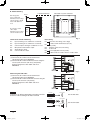
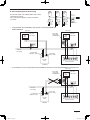
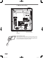
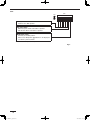
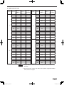
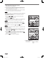
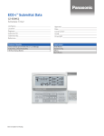
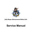
INSTALLATION INSTRUCTIONS
System Controller
Model No. CZ-64ESMC1U
85464369524010
CZ-64ESMC1U_eng.indd 1
2011/09/20 19:14:56
Contents
Page
Product Information ............................................................................................... 2
Alert Symbols ........................................................................................................ 2
Installation Location ............................................................................................... 3
Electrical Requirements......................................................................................... 3
Safety Instructions ................................................................................................. 3
1. General .............................................................................................................. 4
2. Installation site selection .................................................................................... 4
3. How to install the system controller ................................................................... 4
Installation procedure ................................................................................ 5
Electrical Wiring......................................................................................... 6
Basic wiring diagram of control wiring ....................................................... 7
4. Address switch setting ....................................................................................... 8
5. Mode setting .................................................................................................... 11
6. How to perform zone registration ..................................................................... 12
ZONE registration table ........................................................................... 13
(a) Zone registration using the remote controller ......................................... 14
(b) Zone registration using the system controller ......................................... 15
(c) Automatic zone registration using the system controller ............................ 16
7. How to check overlapping of central address no. ............................................ 17
8. Memory back up switch ................................................................................... 18
9. Test run ............................................................................................................ 18
Product Information
If you have problems or questions concerning your Air Conditioner, you will need
the following information. Model and serial numbers are on the nameplate on the
bottom of the cabinet.
Model No.
CZ-64ESMC1U
____________________
Serial No. ____________________
Date of purchase _______________________________________________
Dealer’s address _______________________________________________
Phone number
_______________
Alert Symbols
The following symbols used in this manual, alert you to potentially
dangerous conditions to users, service personnel or the appliance:
This symbol refers to a hazard or unsafe
practice which can result in severe personal
injury or death.
CAUTION
This symbol refers to a hazard or unsafe
practice which can result in personal injury
or product or property damage.
2
CZ-64ESMC1U_eng.indd 2
2011/09/20 19:14:57
Installation Location
•
We recommend that this system controller be installed properly by
qualified installation technicians in accordance with the Installation
Instructions provided with the system controller.
•
•
Do not install this system controller where there are fumes or
flammable gases, or in an extremely humid space such as a
greenhouse.
Do not install the system controller where excessively high heatgenerating objects are placed.
Electrical Requirements
1. All wiring must conform to the local electrical codes. Consult your dealer or a
qualified electrician for details.
2. Wiring must be done by a qualified electrician.
To warm up the system, the power mains must be turned on at least five
(5) hours before operation. Leave the power mains ON unless you will
not be using this appliance for an extended period.
CAUTION
Safety Instructions
•
Read this booklet carefully before using this system controller. If you
still have any difficulties or problems, consult your dealer for help.
The air conditioner is designed to give you comfortable room
conditions. Use this only for its intended purpose as described in the
Operating Instructions.
•
•
•
•
CAUTION
•
•
•
•
Never touch the unit with wet hands.
Never use or store gasoline or other flammable vapor or liquid near
the air conditioner — it is very dangerous.
The air conditioner has no ventilator for intaking fresh air from
outdoors. You must open doors or windows frequently when you use
gas or oil heating appliances in the same room, which consume a lot
of oxygen from the air. Otherwise there is a risk of suffocation in an
extreme case.
Do not turn the air conditioner on and off from the power mains
switch. Use the ON/OFF operation button.
Do not stick anything into the air outlet of the outdoor unit. This is
dangerous because the fan is rotating at high speed.
Do not let children play with the air conditioner.
Do not cool or heat the room too much if babies or invalids are
present.
3
CZ-64ESMC1U_eng.indd 3
2011/09/20 19:14:57
1. General
This booklet briefly outlines where and how to install the system controller.
Please read over the entire set of instructions for the indoor and outdoor units
and make sure all accessory parts listed are with the controller before beginning.
NOTE
Give these instructions to the customer after finishing the installation.
Part Name
Figure
Q’ty
System Controller
1
Rubber bushing
(7/8 in.)
4
Screws for fixture
(1-3/16 in.)
2
Wire joints
2
Switch box
1
T10 cable
1
CRV cable
1
Identification label
1
2. Installation site selection
•
•
Install the system controller at a height of between 3 and 5 ft. above the floor.
Do not install the system controller in a place where it will be exposed to
direct sunlight or near a window or other place where it will be exposed to the
outside air.
Be sure to install the system controller vertically, such as on a wall.
•
3. How to install the system controller
CAUTION
•
•
•
Do not twist the control wiring together with the power wiring or run it
through the same metal conduit, because this may cause a malfunction.
Install the system controller away from sources of electrical noise.
Install a noise filter or take other appropriate action if electrical noise
affects the power supply circuit of the unit.
Do not supply power to the unit or try to operate it until the tubing and
wiring to the outdoor unit is completed.
4
CZ-64ESMC1U_eng.indd 4
2011/09/20 19:14:57
Installation procedure
(1) Remove the flat-top screw on the bottom of the back case. When you open up the decorative cover, you will see two
notches under the controller. Inset a coin or other flat object into these notches and pry off the back case. (Fig.1)
(2) Connect the wires to terminal base of the system controller (see next page).
(3) Attach the back case with the 2 screws (1-3/16 in.) provided.
(4) To finish, fit the back tabs of the back case into the system controller and mount it using the flat-top screw.
Gap
Gap
Switch box
(with cover)
2 screws (1-3/16 in.)
Back case
System
controller
Flat-top Screw
Fig. 1
5
CZ-64ESMC1U_eng.indd 5
2011/09/20 19:14:57
Electrical Wiring
SYSTEM CONTROLLER
<Back side of system controller>
DC24V
DC voltage pulse
Photocoupler input
Allowable contact voltage
and current: 24 V, 10 mA
Pulse width: 300 ms or
more
A1
A2
A3
COM
No-voltage a-contact
static output
Allowable contact voltage
and current: 30 V, 0.5 A
A4
Digital
Input
A5
A6
Terminals for remote monitoring
A1:
Input for turning on air conditioners concurrently.
A2:
Input for turning off air conditioners concurrently.
A3:
Common input for turning air conditioners on or off.
A4:
ON operation state indicator output.
A5:
Alarm indicator output.
A6:
Common indicator output.
Fig. 2
Basic wiring
B1:
Inter-unit control wiring. (Low voltage)
To indoor unit 2P terminal base (U1, U2)
B2:
*No polarity
B3:
Auxiliary of inter-unit control wiring
B4:
Not be used
B5:
Power supply: DC 12 V *No polarity
B6:
To CRV connector or T10 connector on indoor PCB
When using the T10 cable:
(1) Connect B1, B2 to indoor unit 2P terminal base.
(*No polarity). Wire size is AWG#W18.
(2) Connect B5, B6 to indoor PCB T10 connector using the
accessory 6P connector. (with fuse) (*No polarity)
Total wire length is less than 330 ft. and size is
AWG#W18.
Fig. 3
When using the CRV cable:
(1) Connect B1, B2 to indoor unit 2P terminal base.
(*No polarity). Wire size is AWG#W18.
(2) Connect B5, B6 to indoor PCB CRV connector using the
accessory 2P connector. (*No polarity)
Total wire length is less than 330 ft. and size is
AWG#W18.
Fig. 4
NOTE
Connectors are different depending on the indoor unit PCB.
Select the cable according to the indoor unit PCB.
T10 cable
T10 connector
Use the T10 cable.
T10 cable
T10 connector
CRV cable
CRV connector
Use the CRV cable.
6
CZ-64ESMC1U_eng.indd 6
2011/09/20 19:14:57
Basic wiring diagram of control wiring
A max.of 64 indoor units and 30 outdoor units can be
connected in 1system.
Up to 10 system controllers can be connected in
1 systems.
Outdoor
unit-1
Outdoor
unit-2
Outdoor
unit-3
Indoor
unit1-1
Indoor
unit2-1
Indoor
unit3-1
Inter-unit
control wiring
System controller
Remote
controller
•
Remote
controller
Remote
controller
Using Schedule Timer(CZ-ESWC2) with System Controller(CZ-64ESMC1U)
BASIC DIAGRAM
Indoor unit
T10
(YEL)
Indoor unit
Electric Wire
supplied with
CZ-64ESMC1U
Indoor unit
control PCB
U1
Indoor unit
control PCB
T10
(YEL)
U2
U1
U2
Inter-unit
control wiring
Communication
wiring(pink + blue)
Power wiring
(white + black)
B6 B5 B4 B3 B2 B1
Schedule
Timer
System Controller
CZ-ESWC2
•
CZ-64ESMC1U
It is prohibited to connect the Schedule Timer(CZ-ESWC2) with System Controller(CZ-64ESMC1U) simultaneously.
Indoor unit
Electric Wire
supplied with
CZ-64ESMC1U
T10
(YEL)
Indoor unit
control PCB
U1
U2
Inter-unit
control wiring
Power wiring
(white + black)
Communication
wiring (pink + blue)
Schedule
Timer
B6 B5 B4 B3 B2 B1
System Controller
CZ-ESWC2
CZ-64ESMC1U
7
CZ-64ESMC1U_eng.indd 7
2011/09/20 19:14:58
4. Address switch setting
To avoid an electric shock hazard,
DO NOT touch any terminal on the
WA RNI NG Printed Circuit Board with a metal
rod, a screwdriver edge nor a bare
handwhen power is supplied.
To Installers,
After installation and adjustment, be sure to turn the
BACK UP switch ON.
All bits are set off
when shipped from
factory.
PCB of the controller
Dip switch
How to reach the P.C. board
Remove the flat-top screw on the bottom of the back case. When you open
up the decorative cover, you will see two notches under the controller. Inset
a coin or other flat object into these notches and pry off the back case. The
P.C. board on the back of the controller is now visible.
Gap
Gap
8
CZ-64ESMC1U_eng.indd 8
2011/09/20 19:14:58
SW1
Main/sub selection switch
OFF: System controller operates as main controller.
ON: System controller operates as sub-controller.
SW1
ON
1
2
3
4
5
6
7
8
OFF
ALL/ZONE mode selection switch
ALL mode:
All indoor units can be controlled by system controller
ZONE 1, 2, 3, 4 mode:
Indoor units in one of zone 1, 2, 3, or 4 can be
controlled by system controller. All indoor units cannot
be set.
ALL mode
ZONE 1 mode
ZONE 2 mode
ZONE 3 mode
ZONE 4 mode
2
OFF
OFF
ON
OFF
ON
3
OFF
OFF
OFF
ON
ON
4
OFF
5
OFF
ON
ON
ON
ON
Central control/Remote control mode selection switch
OFF: Central control mode.
Individual setting by remote controller can be inhibited
by system controller.
ON: Remote control mode.
Setting by system controller is inhibited by other central
control equipments.
Central control Main/Sub selection switch
(OFF: Main, ON: Sub)
① When AMY adaptor etc. is used with system
controller, set the switch to ON position.
② When only one system controller is used, set the
switch to OFF position.
③ Except ①, when multiple system controllers are
used, set only one system controller to OFF position
others to ON position.
ALL mode system controller to be OFF position.
(recommended)
(Central control) button operation switch
(Central control) button operation is permitted.
OFF:
ON :
button operation is inhibitted.
*All switches are OFF position at shipment.
Fig. 5
9
CZ-64ESMC1U_eng.indd 9
2011/09/20 19:14:58
SW2
SW2
ON
1
2
3
4
5
6
7
8
OFF
Auxilaly switch
Must be set to OFF position.
Beep tone switch
OFF: Beep tone when each button is pushed.
ON: No tone when each button is pushed.
Indication switch
Normally set to OFF position.
When set to ON position, indication is not displayed
on LCD of system controller.
*All switches are OFF position at shipment.
Fig. 6
10
CZ-64ESMC1U_eng.indd 10
2011/09/20 19:14:58
5. Mode setting
According to function of each system controller, set
SW1 as Fig. 7.
(1) Central control/Remote control mode
Central control mode
System controller is used as central control
equipment.
Individual setting by remote controller can be
inhibitted by system controller.
Remote control mode
System controller is used as remote controller.
Setting by system controller is inhibitted by other
central control equipments.
(2) ALL/ZONE mode
ALL mode
All indoor units can be controlled by system
controller.
ZONE mode
Indoor units in one of ZONE 1, 2, 3 or 4 can be
controlled by system controller.
(3) Function of system controller is 10 types according
to combination of central control/remote control
mode and ALL/ZONE mode setting as the table 1.
(4) Stick the system controller unit label in a
conspicuous position.
Central control
mode
Remote control
mode
2 3 4 5 6
2 3 4 5 6
ON
OFF
ON
OFF
ALL
central control
ALL
remote control
Inter-unit control wiring
2 3 4 5 6
2 3 4 5 6
ON
OFF
ON
OFF
ZONE1
central control
ZONE1
remote control
2 3 4 5 6
2 3 4 5 6
ON
OFF
ON
OFF
ZONE2
central control
ZONE2
remote control
2 3 4 5 6
2 3 4 5 6
ON
OFF
ON
OFF
ZONE3
central control
ZONE3
remote control
2 3 4 5 6
2 3 4 5 6
ON
OFF
ON
OFF
ZONE4
central control
ZONE4
remote control
1
2
16
ZONE1
central control
address 1-16
17
18
32
ZONE2
central control
address 17-32
33
34
48
ZONE3
central control
address 33-48
49
50
64
ZONE4
central control
address 49-64
Fig. 7
Table 1
Central control
Remote control
ALL
1. ALL/Central
6. ALL/Remote
ZONE1
2. ZONE1/Central
7. ZONE1/Remote
ZONE2
3. ZONE2/Central
8. ZONE2/Remote
ZONE3
4. ZONE3/Central
9. ZONE3/Remote
ZONE4
5. ZONE4/Central
10. ZONE4/Remote
11
CZ-64ESMC1U_eng.indd 11
2011/09/20 19:14:58
6. How to perform zone registration
To operate the system controller properly, zone registration is required after
finishing the test run (and after setting all indoor unit addresses) using one of the
following methods.
(a) Zone registration using the remote controller
Refer to page 14
(b) Zone registration using the system controller
Refer to page 15
(c) Automatic zone registration using the system controller
Refer to page 16
For methods (a) and (b), you should make a zone registration table manually
before performing the registration as shown on the page 13.
For method (c), zone registration is executed automatically, proceeding from
small indoor unit address and small central addresses to larger numbers in
numerical order. For example:
Central address
NOTE
1
2
3
4
5
6
ZONE-group
1-1
1-2
1-3
1-4
1-5
1-6
Indoor unit address
1-1
1-2
2-1
2-2
2-3
3-1
1. An indoor unit address is assigned to each indoor unit during automatic
address operation. Each indoor unit address combines an R.C. address and
indoor unit number as follows:
1
1
: Indoor unit address (UNIT No.)
Indoor unit No.
Refrigerant circuit No. (R.C. address)
This address is displayed on remote controller for UNIT No. when the UNIT
button is pressed.
2. The central address represents the zone and group number. These
addressed are assigned in ascending numerical order.
12
CZ-64ESMC1U_eng.indd 12
2011/09/20 19:14:58
ZONE registration table
ZONE
1
2
GROUP
Central
address
1
Indoor unit
address
(UNIT No.)
Unit
location
GROUP
Central
address
1
1
33
2
2
2
34
3
3
3
35
4
4
4
36
5
5
5
37
6
6
6
38
7
7
7
39
8
8
8
40
ZONE
3
9
9
9
41
10
10
10
42
11
11
11
43
12
12
12
44
13
13
13
45
14
14
14
46
15
15
15
47
16
16
16
48
1
17
1
49
2
18
2
50
3
19
3
51
4
20
4
52
5
21
5
53
6
22
6
54
7
23
7
55
8
24
8
56
4
9
25
9
57
10
26
10
58
11
27
11
59
12
28
12
60
13
29
13
61
14
30
14
62
15
31
15
63
16
32
16
64
NOTE
Indoor unit
address
(UNIT No.)
Unit
location
1. Assign indoor unit addresses to the desired positions (central addresses)
manually.
2. For group control, only the main indoor unit should be assigned. Sub indoor
units cannot be assigned.
13
CZ-64ESMC1U_eng.indd 13
2011/09/20 19:14:58
(a) Zone registration using the remote controller
(Determination of central address)
In this case, after confirming which indoor unit is connected to the
remote controller and that the air conditioner in the OFF state, you
set the central addresses one at a time.
If the system has no remote controller, connect a remote controller
to the system temporarily. Then follow this procedure.
NOTE
The indoor unit address must already have been set before performing
zone registration. If necessary, refer to the Installation Instructions
supplied with the outdoor unit.
(1) Press the
and
buttons at the same time of the remote
controller for more than 4 seconds.
(2) Do not press
button.
(3) Once in this mode, the UNIT No., CODE No., No. of SET DATA and
indications will flash on the display as shown Fig. 8.
NOTE
In case of group control “ALL” instead of “UNIT No.” will flash on the
display. Select the main indoor unit address by pressing the
button once.
and
( ) buttons.
(4) Set CODE No. to 03 using the
NOTE
The CODE No. 03 must be selected to perform zone registration using
the remote controller.
(5) Set the Central address which you want to assign to the indoor unit
and
( ) buttons according to the zone
address using the
registration table.
(6) Press the
button. The CODE No. and Central address changes
from flashing to ON state. If you make mistake, then press the
button and reset the central address.
(7) Press the
button to finish zone registration.
Fig. 8
For example, in this case
Indoor unit address: 1-8
Central address :
17 (ZONE 2, GROUP 1)
Fig. 9
14
CZ-64ESMC1U_eng.indd 14
2011/09/20 19:14:59
(b) Zone registration using the system controller
In this case, you set all Central addresses by
system controller at once manually.
and
buttons at the same time
(1) Press the
for more than 4 seconds.
and CODE No. C1 will flash.
(2) After confirming that CODE No. C1 is displayed,
button. Once in this mode, a change
press the
takes place as Fig. 10.
(3) Select the zone and group No. which you want to
set with
and
(GROUP) buttons.
buttons.
If already set, press the
(4) Set the unit No. (Indoor unit address) with
and
buttons, according to the zone registration table.
button
R.C. No. .....................
Indoor unit No. ...........
button
(5) Press the
button.
GROUP No. turns ON and UNIT No. (Indoor unit
address) changes from flashing to ON state. UNIT
No. is registered to selected ZONE No. and GROUP
No.
If you make mistake, then press the
button and
reselect the ZONE, GROUP and UNIT No.
(6) Register the other UNIT No. in the same way by
following the steps (3) to (5).
(7) Finally, complete the registration by pressing the
button.
flashes for a few minutes, then OFF.
If no data is
registered
no number
is displayed.
Selected
group No. if
no data is
registered.
If data is
registered
the unit No.
is displayed.
Fig. 10
For example, in the case at left
Zone 3, group No. 7
Unit No. (indoor unit address) 2-8
Unit No. 2-8 is registered to zone 3-group 7.
Fig. 11
15
CZ-64ESMC1U_eng.indd 15
2011/09/20 19:14:59
(c) Automatic zone registration using the system controller
and
buttons at the same time for more than 4
(1) Press the
seconds.
and CODE No. C1 will flash.
and
( ) button and
(2) Select CODE. No. C2 by pressing
press the
button.
C2 changes from flashing to ON state and automatic zone
registration will start.
(3) Registered GROUP No. will be disappeared all.
(4) Central address will be assigned from small indoor unit address to
large one in numerical order automatically.
changes from flashing
Finishing automatic zone registration,
to OFF.
(5) If the error is happened, the “CHECK” starts flashing and zone
registration finishes at this time. Press the
button.
(6) Finally, complete automatic zone registration mode by pressing the
button.
flashes for a few minutes, then OFF.
Fig. 12
16
CZ-64ESMC1U_eng.indd 16
2011/09/20 19:15:00
7. How to check overlapping of central address no.
(1) Press the
and
buttons at the same time for more than 4
seconds.
and CODE No. C1 will flash.
(2) Select CODE. No. C3 by pressing
,
( ) button and
press the
button.
C3 changes from flashing to ON state and
will flash. Then
auto. overlap checking will start.
(3) If C3 changes from ON to flashing and
stops flashing and
disappears, there is no overlapping.
Then finally, complete the auto overlap checking mode by pressing
the
button.
(4) If some of GROUP No., ZONE No. and UNIT No. flash, you should
try again the zone registration.
① Select CODE No. C1 by pressing
,
( ) button and
press the
button.
② Select the flashing GROUP No. with ZONE and GROUP button.
Then press the
button and reselect the ZONE, GROUP and
UNIT No.
③ Then finally, complete the auto. overlap checking mode by
pressing the
button.
Fig. 13
17
CZ-64ESMC1U_eng.indd 17
2011/09/20 19:15:00
8. Memory back up switch
ON
OFF
Check the back up switch is ON for back side of system controller PCB.
Back up switch
Back up battery
9. Test run
(1) Power on for all indoor units. Next, power on for system controller.
will flash, checking the indoor unit address automatically.
(2) If group No. displayed on system controller is not same as indoor unit No.*
which is connected, see Fig. 7 and setting again.
*In case of group control, main unit No. only.
18
CZ-64ESMC1U_eng.indd 18
2011/09/20 19:15:00
19
CZ-64ESMC1U_eng.indd 19
2011/09/20 19:15:00
Printed in Japan
CZ-64ESMC1U_eng.indd 20
2011/09/20 19:15:00