1
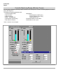
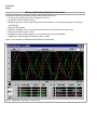
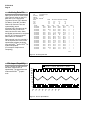
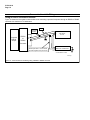
51-52-03-16
12/99
Page 1
Specification
LeaderLine PC Software
Overview
Honeywell’s LeaderLine PC Software
(LPCS) is a cost effective and efficient
means to monitor, archive, and
configure Honeywell’s LeaderLine
controllers and recorders using a
Windows™-based Personal Computer
program.
These products include:
UDC3000 Universal Digital Controller
UDC3300 Universal Digital Controller
UDC6000 Process Controller
UDC6300 Process Controller
DPR3000 Digital Process Recorder
DPR100C/D Pen/Multipoint Digital
Recorders
DPR180 Digital Process Recorder*
DPR250 Digital Process Recorder*
*Monitoring and Archiving only
The software has been developed
around the industry standard Windows
™95/98/NT operating system and is
designed for either novice or experienced computer users.
The familiar windows environment and
the on-line and context-sensitive help
utility allow the first time user to quickly
accomplish the required tasks.
Software Capabilities
Software capabilities include:
Set-up - installs the LPCS software
into the personal computer and allows
changes to the installed settings and
languages.
Network Configuration - selects
device node addresses and tag names.
Product Configurator - configure
devices either on-line or off-line. All
devices, except DPR180/250 are totally
configurable with full configuration
dependencies supported. Default
device database templates provide for
ease of initial device configuration.
Operator Displays - let the operator
monitor, archive, and selectively
change device variables on-line to tune
your process.
Converter
RS232
Up to 16
addresses
ASCII RS 422/485
PV 6000
SP 6000
L
FC
3000
SP3000
UDC3000
UDC3300
UDC6000
UDC6300
DPR100
DPR180
DPR 3000
DPR250
24063
Figure 1 - LeaderLine PC Software
Standard Features
Easy Set-up and Use - the software
package is simple to install and
requires no advanced PC skills.
The set-up procedure uses preformatted displays and on screen
selection.
Transportable Software - this
software is transportable across
Windows® 95 based, IBM® equivalent
desktop and portable Personal
Computers having a minimum 486
processor and 16 MB of memory.
Network Configuration - lets you
specify the name of a network.
Products are assigned to the network
with associated addresses and tag
names.
Standard Features, cont.
On-line/Off-line Device Configuration
- all devices, except DPR180/250 are
totally configurable either On-line or
Off-line with full configuration dependencies supported during configuration.
Default device database templates are
provided for ease of initial device
configuration. A record of device
configuration can be printed out.
Real Time Monitoring - real time
operating displays are pre-formatted.
Multiple display selection and
organization within the workspace is
supported. UDC displays can be mixed
with a DPR Trend display on the same
screen. DPR Trend displays can be
mixed with loop displays. Front Panel,
and Trend views are available for
UDCs.
Help - program accesses On-line and
Context sensitive help.
Sensing and Control, 11 West Spring Street, Freeport, Illinois 61032
Printed in U.S.A. ■ © Copyright 1999—Honeywell Inc.
51-52-03-16
Page 2
Standard Features, cont.
Standard Features, cont.
Standard Features, cont.
Archiving - is run as a background
task, allowing you to run other
operations while archiving is in
progress. For recorders you can store
PV’s (up to 32 for DPR3000) plus
related Alarm and Digital Input status
per recorder.
Data Logging and Storage with
Analysis - data is stored in ASCII
format on the PC hard disk and can be
easily imported to most spreadsheet
programs such as Microsoft Excel™
and Lotus 1,2,3™ to enable
presentation in graphical format or for
further calculations.
Multilingual - support for international
sales include English, French and
German.
For controllers, you can store PV’s,
Setpoint values, Output values,
and On/Off Alarm states.
Communications - lets you supervise
16 addresses with a mix of recorders
and controllers. There are 128 points of
data available.
Main Menu
The Main Menu bar is located along the
upper edge of the window
(See Figure 2).
The LPCS program’s Main Menu is the
top level menu that allows access to
drop-down menus that will navigate you
through the application and let you
quickly select a specific function.
Undo
Copy
Each menu item describes its
functionality.
A Toolbar at the top of the window
offers shortcuts to the most common
menu items.
A Status bar at the bottom of the
window indicates information about the
current window including downloading
and uploading status.
Cascade
Horizontal Tile
Vertical Tile
A rrange Icons
Window
Tr ending
Toolbar
Status Bar
Contents
Tip of the Day
About Honeywell LPCS...
Device Diagnostic ...
Password
Ctrl+ Z
Ctrl+ C
Dependencies Information
Language
Communication Parameters ...
Network Selection ...
New Configuration ...
Open Configuration ...
New Network
Open Network ...
Close
Save
Save As ...
Remove Configuration
Remove Network ...
Print
Ctrl+ P
Print Preview
Print Configuration...
Preview Changes
Ctrl+ R
Ctrl+ H
Ctrl+ V
Ctrl+ A
Upload Configuration ...
Download Configuration
Verify Configuration...
Monitor...
Select Product...
Archiving Parameters ...
Start Archiving
Archive
E xit
Figure 2 - Main Menu
Toolbar
The toolbar (Figure 3) contains
several commonly used functions that
can be accessed by clicking on the
corresponding button.
The buttons are grouped to show
relationships.
Save
Print
Open Configuration
New Configuration
Figure 3 - Toolbar
Copy
Monitor
Network Selection
Download Configuration
Upload Configuration
51-52-03-16
Page 3
Configuration Display and Template for Product Configuration
Full Product Line configuration: Off-line or On-line. (except DPR180 and DPR250 Recorders)
This function includes checks and adjustments for all dependencies associated with configuration.
Off-line configuration lets you create new configuration databases from a template.
On-line configuration lets you upload configuration data and modify the displayed configuration of a device that is connected
to the link.
In either case, configuration can be saved and downloaded to specific devices on the network.
Figure 4 is an example of a UDC3300 default configuration template with all options selected.
Figure 4 - Configuration Option Selection and Template
51-52-03-16
Page 4
Controller Monitoring Display (Windows Format)
You can group displays by opening multiple windows in the work space to create a monitoring display for control
loops. (See Figure 5)
The displayed operating parameters are:
• Process Variable Value
• Setpoint Value*
• Setpoint Source*
• Mode* - (Auto/Manual)
• Alarms Status (On/Off only)
• Rate Value in minutes*
*Value or selection can be changed.
• Bargraph of
Setpoint(Optional SP Pointer)
Process Variable (Eng. Units)
Output Values* (%)
• Proportional Band or Gain value*
• Reset Value in min or rpm*
51-52-03-16
Page 5
Monitoring/Trending Display For Controllers
A Trending Set Up window lets you choose, at trending start-up, up to four parameters to trend for each loop
address selected.
A page assignment tab in the set-up window lets you assign two loops (addresses) per page to be displayed in
the controller trending display window.
The ControllerMonitoring /Trending window enables operations such as:
• Displays the address and tag name of the device.
• Four parameter fields display the parameters chosen in the Set Up window.
• Four alarm fields indicate alarm states, if configured
• Color coded indication of selected parameters to be scaled for the viewing area
• MIN and MAX fields let you position the trend display appropriately in the window.
• Page selection button allows display of up to 8 pages of two addresses each
• Operating Window button at the top of the window lets you edit On-line Setpoint, Output, Setpoint Source and
Mode values of device selected.
Figure 6 is an example of a Controller Monitor/Trend window.
Figure 6 - Controller Monitor /Trend Window
51-52-03-16
Page 6
Monitoring/Trending Display For Recorders
The Recorder Monitoring /Trending window enables operations such as:
• Trending of 8 Inputs per page can be displayed in real time.
• Change the vertical scale of the curves
• Display the tag name, value in engineering units of each channel, up to 8 channels per page, up to 4 pages
(for DPR3000)
• Display the alarm states
• Send user messages of up to 30 characters to the recorder to be printed on the recorder chart
• Display a warning message on alarm
• Page selection button allows display of up to 32 channels per recorder (DPR3000)
• Capability to change background selection to Black or white
Figure 7 is an example of a DPR3000 recorder Monitor/Trend window.
Figure 7 - DPR3000 Recorder Monitor /Trend Window
51-52-03-16
Page 7
Archiving
The LPCS software package lets
you store data from up to 16
addresses (Max 128 data points) on
the PC’s hard disk.
The software can save PV, Alarm,
or Digital Input status data for
recorders and PV, SP, Output and
On/Off alarm states through a
parameter selection window.
The current date, time and channel
numbers (DPR only) are also
systematically saved each time the
inputs are scanned and the data is
archived.
After enabling the archiving function
for a specific device or group of
devices, the software will
automatically start the storage for a
user-configured time period.
A screen indication on the
monitoring/trending display alerts
the operator that the archiving
function has been activated for the
current device (DPR only) in a
Status Bar indication.
The archiving function is still active
when you switch to display another
device
The software automatically indicates
the free space available on the hard
disk and the memory space
required for data storage.
Archiving Set Up Window
The Archiving Parameter Window is set up for all the devices connected on the communications link and enables
operations such as:
• Data storage - ASCII files
• Archiving time - Days, Hours, and Minutes selectable
• Scanning Period - Based on multiple of the scanning rate.
• Number of consecutive files
• Selection of various parameters for recorders and controllers
Figure 8 is an example of an Archiving Parameter Window.
Figure 8 - Archiving Parameter Window
51-52-03-16
Page 8
Archiving Data File
File:
c\lpcs\boiler01.dpr
Recorder: DPR3000
Address:
1
Tag Name: BOILER
Name:
SINE
Unit:
mV
Low:
30
High:
50
CH1
TIME
DATE
46.66
19.33
11/01/1996
46.85
19.33
11/01/1996
46.94
19.33
11/01/1996
47
19.33
11/01/1996
47.21
19.33
11/01/1996
47.35
19.33
11/01/1996
47.23
19.33
11/01/1996
47.37
19.34
11/01/1996
47.54
19.34
11/01/1996
47.48
19.34
11/01/1996
47.24
19.34
11/01/1996
47.43
19.34
11/01/1996
47.33
19.34
11/01/1996
47.22
19.34
11/01/1996
47.19
19.34
11/01/1996
47.06
19.34
11/01/1996
47
19.34
11/01/1996
Data can be stored in ASCII format
(See Figure 8) either on the PC’s
hard drive or on a floppy disk
Tag name, Device Type, address,
File Name, Chart Min. and Max.,
Channel #, Date and Time are
systematically stored.
Archiving DATA file name can be
selected as well as data to be
stored such as PV value, Alarm,
and Digital Input status for recorders
and PV, SP, Output and On/Off
alarm states for controllers..
Data is stored in such a way that it
can be imported into most current
spreadsheet software packages
such as EXCELTM and LOTUS TM for
further manipulation.
(For example: Graphical and
computing).
TRI-WAVE SQUARE CHANNEL
mV
mV
mV
20
0
0
55
40
60
DIG 1 ACH 1
CH4
CH3
CH2
0
0
34.52
34.84
50.95
0
0
34.51
34.95
51.12
0
0
34.51
34.94
51.46
0
0
34.49
34.97
51.63
0
0
34.49
35.12
51.8
0
0
34.5
35.2
51.98
0
0
34.51
35
52.14
0
0
34.51
35.11
52.32
0
0
33.48
0.14
52.38
0
0
30.64
0.14
52.19
1
1
28.07
0.14
51.98
1
1
25.73
0.14
51.8
1
1
23.59
0.14
51.61
1
1
21.63
0.14
51.42
1
1
19.85
0.14
51.23
1
1
18.23
0.14
51.04
1
1
16.75
0.14
50.85
24072
Figure 8 - Archiving Data File
File Import Capability
Figure 9 shows the ASCII file that
has been imported into an
spreadsheet. The graph has been
made with EXCEL TM graphic
tools.
INPUT01
20
18
16
14
12
10
8
6
4
2
0
INPUT02
INPUT03
1
1
1
1
1
1
1
1
19: 19: 19: 20: 20: 20: 20: 20: 20:
33: 43: 54: 04: 15: 25: 35: 46: 56:
0
0
0
0
0
0
0
0
0
Figure 9 - Excel™ Spreadsheet
INPUT04
51-52-03-16
Page 9
Condensed Specifications
Platform
The LPCS makes use of commercially available desktop and laptop PC platforms:
CPU:
Display:
RAM:
Hard Disk
Floppy:
Ports:
80486, 66mHz Pentium families*, KG-2**
VGA Color, VGA Monochrome for configuration displays only
16 MB min.
50 MB min. for LPCS application
3.5” 1.44 MB
Serial: Converter required for RS232 to RS485/422 conversion•
Communications
• The LPCS communicates with the specified devices through the PC serial ports.
The computer must be connected to the devices by way of the RS232 to RS485
converter or by way of a RS485 PC card, which utilizes standard communication
resources.
• Multi-drop RS485 ASCII, up to 16 addresses, mixed product type. For example:
Recorders and controllers
- Link supports up to 128 data points
- Multi-port switching capability
• RS232 to RS485/422 converter required:
- recommend Black Box (Model IC109A) or Westermo (Model MA42)
Operating System
Operates in the Windows 95/98/NT environment.
Compatibility
The LPCS is compatible with the following commercially available packages:
Operating System:
Database:
Spreadsheet:
Word Processing:
Archiving File:
TM
Windows 95 release 4.00.950A*** or later (Service
Pack 1), Windows 98, or Windows NT 4.0 or later
Microsoft Access
Microsoft Excel, Lotus 1-2-3
Microsoft Word for Windows
Lotus 1-2-3, Excel, ASCII Editor
Archived Data
An ASCII format file for recorder historized data that can be opened from
packages such as Excel, Lotus 1,2,3, or any ASCII Editor.
Documentation
• On-line Help
• User Manual and displays in English, German, or French
Honeywell Products Supported
Universal Digital Controllers and Digital Process Recorders with RS485
Communications Option:
Device
UDC6000 Controller
UDC6300 Controller
UDC3000 Controller
UDC3300 Controller
DPR3000 Recorder
DPR100 Recorders
DPR180 Recorders
DPR250 Recorders
User Configuration Database
Software Version
7115 or later
8102 or later
3109, 3111 or later
3X04 or later
Rev BD or later
Rev A*38A or AK or later
001AG or later
001AG or later
Available through menu selections
51-52-03-16
Page 10
Communications Link Wiring
Using an RS232 to RS485 Converter
Figure 10 shows the Honeywell communications link connecting a personal computer through an RS232 to RS485
converter to a maximum of 16 addresses.
Shield
120 Ohm
Resistor
Computer
RS232
Output
RS232
to
RS485
+
–
1ST Device
on Link
T+/R+
T-/R-
Converter
Twisted pair shield - connect shield
wire with Supplied Crimp Connector
To other devices on link
Maximum 16 addresses
120 ohm resistor between A and B
on last device on link
22949.ppt
Figure 10 - Communications Link Wiring Using a RS232 to RS485 Converter
51-52-03-16
Page 11
Ordering Information
For the complete ordering information for LeaderLine PC Software,
call 1-800-343-0228 in the U.S. or contact your local Honeywell Sales
Office.
Specifications are subject to change without notice.