1
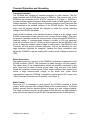
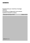
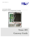
CP485x4
User’s Manual
Version 1.0
© 2005 ZYPEX, Inc.
CP485-4 User’s Manual
Table of Contents
Table of Contents
Product Description
1
CP485x4 Configuration & Setup
Power
Baud Rate
Control Mode
Duplex Mode
Termination
Key-Down Delay
2
2
2
2
2
3
3
Control Mode Description
RTS Mode
Data Mode
4
4
4
Duplex Mode Description
Full Duplex Mode
Half Duplex Mode
5
5
5
Termination Description
5
LEDs
5
DIP Switch Settings
6
Transient Protection and Grounding
Transient Protection
Shield Connection
Static Control
7
7
7
7
Connectors
Power
RS-232
9
9
9
Power Consumption
9
Product Specifications
10
Contact Information
11
CP485-4 User’s Manual
Table of Contents
Product Description
The CP485x4 line driver is a quad RS-232 to RS-485 interface converter. It
allows an RS-232 device to reliably transmit data over long distances (up to 4000
feet). The CP485x4 has many features not normally found in typical line drivers,
and is intended for operation in harsh industrial environments.
The CP485x4 may be used in point-to-point applications as well as multi-drop
applications using either 4-wire or 2-wire configurations. Up to 128 devices may
be connected together on one communication line in half-duplex mode, or 64
devices in full-duplex mode.
A variety of timing and control options are available on the CP485x4. Each
channel is individually isolated, and may be operated in either RTS mode or Data
mode. In RTS mode, the RS-232 RTS signal controls the RS-485 driver. In Data
mode, the CP485 controls the RS-485 driver. When incoming data is detected on
the RS-232 RX line, the CP485 enables the RS-485 driver, and starts buffering
the incoming data. After a 2-character time delay (keyup delay), the data is
transmitted on the RS-485 line. When all of the characters have been sent, the
CP485 leaves the RS-485 driver enabled for a fixed time of either 50 or 500
microseconds (DIP Switch selectable) to allow the transmitted bytes to propagate
out, and then disables the RS-485 driver (keydown delay).
Electronic switches are used to control all configuration options. The user need
only set the baud rate, duplex mode (full or half), control mode (RTS or Data) and
whether the line is to be terminated.
A unique capability of the CP485x4 is the ability to sense the presence of a
received RS-485 carrier (remote RS-485 driver enabled). This is very useful for
controlling devices that require a turn-on delay before data can be transmitted
(e.g., devices such as radio modems).
All timing functions are crystal controlled and provide very accurate and stable
delays. Temperature and voltage fluctuations will not affect the CP485x4’s
operation.
The CP485x4 has 1500-volt optical isolation between the RS-232 side and the
RS-485 side. The RS-485 lines are protected with 2 stages of surge protection.
CP485-4 User’s Manual
1
Version 1.0
CP485x4 Configuration and Setup
Power
Connect a DC power supply to J5 pins 1 & 2. Connect the positive side to J5 pin
1, and the common or return to J5 pin 2. Voltage can be 5 VDC to 30 VDC.
CAUTION! The CP485 will be damaged if these connections are reversed!
Connect J5 pin 3 to an earth ground. This connection enables the first stage of
transient protection for each RS-485 channel, and keeps any static charge from
building up on the RS-485 lines.
The earth ground must be a short wire, directly to a suitable
building ground, using 14-gauge wire (minimum size wire)!!!
Baud Rate
Set DIP Switches 1 – 3 to configure the channel for the desired baud rate (see
DIP Switch Settings). The data format is automatically set to 8 data bits, no parity
and 1 stop bit.
Control Mode
Set DIP Switch 4 to the desired Control Mode setting (RTS control or Data
control). “DATA” mode is with DIP Switch 4 in the ON position. See the “Control
Mode Description” in the next section for a full explanation of these two modes of
operation.
If you set DIP Switch 4 to ON, then you must set DIP Switch 7 to be either 8-bit
mode or 9-bit mode (OFF or ON, respectively).
Use 8-bit mode (in “DATA” mode only) if your data packets have either:
• 7 data bits, plus parity (odd or even)
• 8 data bits, no parity
Use 9-bit mode (in “DATA” mode only) if your data packets are 8 data bits, with
parity.
Duplex Mode
Set DIP Switch 5 to the desired Duplex Mode setting (full or half duplex). Full
duplex is 4-wire mode, and half duplex is 2-wire mode. In half duplex mode,
electronic switches connect the TX pair to the RX pair. The RS-485 lines may be
connected to either the TX+ / TX- pair or the RX+ / RX- pair.
CP485-4 User’s Manual
2
Version 1.0
Termination
Set DIP Switch 6 to enable or disable termination of the RS-485 trunk. The
“TERM” LED will illuminate if termination is enabled.
Key-Down Delay
DIP Switch 8 is only used in “DATA Mode”, and allows you to set a very short or
very long key-down delay. This is the amount of time that the RTS line is held
ON, following the transmission of the last bit of the last byte of a data packet.
The OFF position is a key-down time of 10 microseconds. The ON position of
this switch makes the key-down time 50 microseconds. For short, hard copper
lines, we recommend that this switch be in the OFF position. For “slow” devices
like modems, we suggest that you position DIP Switch 8 in the ON position.
Factory Test Options
If any DIP Switch is moved (from OFF to ON, or ON to OFF) during the one- to
two-seconds of power-up self-test (when the lights flash in the pretty power-up
sequence, it is in self-test mode), then the CS485x4 enters a “factory test mode”.
At this point, the various DIP Switches are used to enable various factory test
options. The only way to get the CS485x4 out of this “factory test mode” is to unpower the device, wait a few seconds, then re-apply power.
CP485-4 User’s Manual
3
Version 1.0
Control Mode Description
RTS Mode
When RTS Mode is selected (DIP Switch 4 ON), the baud rate setting has no
effect, and any type of data format may be used (7 data bits, even parity, 2 stop
bits, or 8 data bits, odd parity, 1 stop bit, for example). The RS-232 RTS signal is
used to control the RS-485 driver.
Data Mode
When Data Mode is selected (DIP Switch 4 OFF), DIP Switches 1 – 3 are used
to set the baud rate. Data on the RX-232 RX line is used to control the RS-485
driver. The RS-232 RTS signal is not used.
The data format handles both 1 and 2 stop bits. However, the CP485 does need
to know how many TOTAL data bits (data plus parity) will be in each byte. The
options are: 8-bit mode (7 data bits, plus a parity bit, or 8 data bits with no
parity), or 9-bit mode (8 data bits, with a parity bit). DIP Switch 4 set to OFF
selects 8-bit mode, while setting DIP Switch 4 to ON selects 9-bit mode.
When incoming data is first detected on the RS-232 RX line, the RS-485 driver is
enabled and the incoming data is stored in a buffer. After a 2-character time
delay (for the selected baud rate), the buffered data is then transmitted out the
RS-485 trunk. This allows the CP485 to provide a turn-on delay, which allows
any transients on the RS-485 lines to settle before data is sent.
After the transmission of the last character, the CP485 keeps the RS-485 driver
enabled for some small time period (50 or 500 microseconds; DIP Switch
selected) to allow the data to propagate down the RS-485 lines. This is called a
“key-down delay”, and makes sure the data is completely received at the other
end, before the RS-485 transmitted is disabled. This insures that the receiver on
the end-devices does not have “splatter” or “squelch noise” at the end of the data
packet, and yet is expected to be a short enough time period that no response
from the other device is lost. This time is somewhat arbitrary, and you may have
to try different settings of DIP Switch 8 to see what works best with your wiring
and device configurations. Generally speaking, hard-copper lines don’t require
much key-down delay, and DIP Switch 8 should be OFF; whereas modems
(especially RF modems) need much longer “quiet times”, and we suggest that
these applications DIP Switch 8 should be ON. If you have problems with very
slow (antique) devices, especially older, low-frequency RF modems, these
timings can be changed at the factory—Contact Zypex or Centaurus Prime if any
longer time period is required for your particular application.
CP485-4 User’s Manual
4
Version 1.0
Duplex Mode Description
Full Duplex Mode
In Full Duplex Mode, data is transmitted on the TX+ / TX- pair, and data is
received on the RX+ / RX- pair. The RX+ / RX- pair is always active.
Half Duplex Mode
In Half Duplex Mode, the TX+ / TX- pair is internally connected to the RX+ / RXpair. TX+ is connected to RX+, and TX- is connected to RX-. Either pair may be
used (but not both).
Termination Description
If termination is enabled in full duplex mode, the TX+ / TX- pair is terminated and
the RX+ / RX- pair if terminated.
If termination is enabled in half duplex mode, the TX / RX combination is
terminated.
Termination consists of a 120-ohm resistor across the two RS-485 lines, plus a
1.2K pull-up resistor and a 1.2K pull-down resistor.
LEDs
RTS LED
The RTS LED is illuminated when the RS-485 driver is enabled.
TX LED
The TX LED is illuminated when data is being transmitted on the RS-485 lines.
RX LED
The RX LED is illuminated when data is being received on the RS-485 lines.
DCD LED
The DCD LED is illuminated when the voltage on the RX+ / RX- pair is greater
than 800mV. If the RX pair is terminated (either end), the DCD LED will illuminate
when the remote RS-485 driver is enabled. If the RX pair is not terminated, the
LED will be ON continuously.
TERM LED
The TERM LED is illuminated when the RS-485 channel is terminated.
CABLE LED
The CABLE LED is illuminated when an active RS-232 cable is plugged into the
DB-9 connector. The LED will not illuminate if the RS-232 cable is crossed or
improperly wired.
CP485-4 User’s Manual
5
Version 1.0
DIP Switch Settings
Switch
Switch 1 Switch 2 Switch 3
OFF
OFF
OFF
ON
OFF
OFF
OFF
ON
OFF
ON
ON
OFF
OFF
OFF
ON
ON
OFF
ON
OFF
ON
ON
ON
ON
ON
Description
Baud Rate Select
1200 Baud
2400 Baud
4800 Baud
9600 Baud
19.2K Baud
38.4K Baud
57.6K Baud
115.2K Baud
Switch 4
Data / RTS Mode
OFF – Data Mode
ON – RTS Mode
Switch 5
Duplex Select
OFF – Half Duplex
ON – Full Duplex
Switch 6
RS-485 Termination
OFF – No Termination
ON – Termination Enabled
Switch 7
Data-Mode ONLY: total number of bits
OFF – 8-bit mode (e.g. 8-bit, no parity)
ON – 9-bit mode (e.g. 8-bit w/parity)
Switch 8
Key-Down Delay
OFF – Normal (50 microseconds)
ON – Slow (500 microseconds)
CP485-4 User’s Manual
6
Version 1.0
Transient Protection and Grounding
Transient Protection
The CP485x4 has 2-stages of transient protection for each channel. The first
stage connects each RS-485 data line to a SiDACtor. The common side of the
SiDACtors are connected to the “EARTH” terminal of J5 (Figure 1). SiDACtor’s
provide ultra-fast transient response and provide a path to earth ground for highvoltage transients. The second stage of transient protection uses Transorbs that
are connected to the isolated common of the RS-485 section. The Transorbs
make sure all transient signals are clamped to within the normal operating
voltage of the RS-485 electronics.
Under certain conditions, some devices introduce a large ac or dc voltage on the
RS-485 communication lines (referred to as common-mode voltage). This does
not present a problem unless the common-mode voltage exceeds the SiDACtor’s
clamping voltage. If common-mode voltages in excess of 60V are expected,
leave the connection from J5-3 (Earth) to ground open so that the SiDACtor’s will
not try to clamp the common-mode voltage to earth ground. The SiDACtor’s and
Transorbs will still provide transient protection, but not as effectively for very
large transients (lightning for example). Leaving the Earth connection open
allows the CP485x4 to operate reliably with common-mode voltages in excess of
100V.
Shield Connection
The isolated ground or common of the CP485x4 is connected to center pin of the
RS-485 connector (SHLD). The connection is made through a 100-ohm resistor.
The shield wires of the communication cables are normally connected to this
point. Care must be taken to avoid ground loops. Only one end of the shield
should be connected to earth ground. Under some conditions other devices may
induce a large common-mode voltage on the shield wire. Under these
circumstances, leave the CP485x4’s connection to earth ground (J5-3) open (see
“485x4 Transient Protection and Grounding”, and Figure 1).
Static Control
When pin J5-3 is connected to earth ground, the CP485x4 provides a “bleed
resistor” which prevents static voltage buildup on the isolated section. The bleed
resistor ensures that the isolated section is always at a safe voltage potential.
The same connection provides a filter capacitor that deflects any high-frequency
noise that may be induced on the RS-485 communication lines to earth ground.
CP485-4 User’s Manual
7
Version 1.0
CP485-4 User’s Manual
8
Version 1.0
Connectors
Power (J5)
Pin
J5-1
J5-2
J5-3
Description
+5 Vdc to +30Vdc
Common for J5-1
Earth Ground
RS-485 (J7 – J10)
Pin
Jx-1
Jx-2
Jx-3
Jx-4
Jx-5
Description
TX+
TXIsolated Common (Shield)
RX+
RX-
RS-232 (J1 – J4)
Pin
Jx-1
Jx-2
Jx-3
Jx-5
Jx-7
Jx-8
Description
DCD
RX Data
TX Data
Common
RTS
CTS
Signal
Output
Output
Input
Ground
Input
Output
Power Consumption
Voltage
5 Vdc
12 Vdc
16 Vdc
24 Vdc
30 Vdc
CP485-4 User’s Manual
Current (Typical)
1.0 Amp (inrush); 400 mA operational
9
Version 1.0
CP485x4 Specifications
RS-485 Channels
4 Individually Isolated RS-485 Channels
Max Data Rate
250kbps (RTS control)
1200 to 115.2K Baud (Data Mode)
Line Loading
¼ Load, 128 nodes / trunk
Isolation
1500V RMS
Operation
2-wire Half-Duplex, 4-wire Full-Duplex
Data Format
7 Data bits with parity, or 8 data bits (both with or without parity);
1 or 2 Stop Bits
Input Voltage
+5Vdc to +30Vdc
Removable 3-pin connector
Transmit Control
RTS Control or DATA Control
2 character keyup delay (Data Mode ONLY)
50 or 500 microsecond key-down delay (Data Mode ONLY)
DCD Operation
True Carrier Detect or synthesized Data Detect
Status Indication
LED Indicators for TX, RX, RTS, DCD
Termination, RS232 Cable and Power
Transient Protection
Power Input
Peak Pulse Power – 600 watts (10/100us waveform)
Peak Surge Current – 100 amps (8.3ms single half sine-wave)
RS-232 Port
ESD Protected
±15kV Human Body Model
±8kV Contact Discharge
±15kV Air-gap Discharge
RS-485 Port
2-Stage Surge Protection
1st Stage: 150A Peak Pulse (2x10us waveform)
2nd Stage: 600 watts (10x100us waveform)
Operating Temperature Range
−40°C to +85°C
10% to 90% RH (non-condensing)
Size
4.0 in. × 8.0 in.
Mounting
Standoffs with #4 machine screws
CP485-4 User’s Manual
10
Version 1.0
Contact Information
ZYPEX, Inc.
2795 E Bidwell Street #100-405
Folsom, CA 95630
(916) 983-9450
(916) 983-9448 fax
www.zypex.com
[email protected]
Contact Information
Centaurus Prime
4425 Cass Street, Suites A-B
San Diego, CA 92109
(858) 270-4552
(858) 273-7769 fax
www.centaurusprime.com
[email protected]
CP485-4 User’s Manual
11
Version 1.0