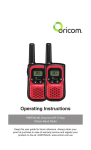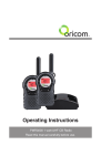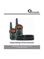
1
®
Operating Instructions
PMR1200 40 Channel UHF 2 Way
Citizen Band Radio
®
Table of contents
Safety Information and Warnings.................................... 4
Getting Started............................................................... 8
Oricom PMR1200 instructions...................................... 12
Operation...................................................................... 13
UHF channels and frequencies...................................... 22
Warranty information (Australia).................................... 24
Customer support......................................................... 26
This unit complies with all relevant Australian and New Zealand approval
requirements including radio communications (Electromagnetic Radiation
Human Exposure) standard 2003.
3
Safety Information and Warnings
Safety Information and Warnings
WARNING
4
Information on Safe Operation
Read This Information Before Using Your Oricom Radio.
Radio Antenna
Do not use any radio that has a damaged antenna. If
a damaged antenna comes in contact with the skin, a
minor burn may result.
Unauthorized antennas, modifications, or attachments
could damage the radio and violate compliance. Do NOT
change or modify the antenna.
Do NOT hold the antenna when the radio is “IN USE.”
Holding the antenna reduces range and may cause
bodily harm.
Safety and general use whilst in a vehicle
Check the State and Federal laws and regulations
regarding the use of two way radios in the area where
you drive, and always obey them.
For Vehicles fitted with Air Bags
Do not place your radio in the area over an air bag or in
the air bag deployment area. Air bags inflate with great
force. If a radio is placed in the air bag deployment area
and the air bag inflates, the radio may be propelled with
great force and cause serious injury to the occupants of
the vehicle.
Batteries
All batteries can cause property damage and/or bodily
injury such as burns if conductive material such as
jewelry, keys, or beaded chains touches exposed
terminals. The material may complete an electrical
circuit (short circuit) and become quite hot. Exercise
care in handling any charged battery, particularly when
placing it inside a pocket, purse, or other container with
metal objects.
Do not replace or charge batteries in a potentially
explosive atmosphere. Contact sparking may occur
while installing or removing batteries and cause an
explosion.
Safety Information and Warnings
WARNING
Potentially Explosive Atmospheres
Turn your radio OFF when in any area with a potentially
explosive atmosphere. Sparks in such areas could cause
an explosion or fire resulting in injury or even death.
NOTE: Areas with potentially explosive atmospheres
are often, but not always clearly marked. They include
fueling areas such as below deck on boats; fuel or
chemical transfer or storage facilities; areas where the
air contains chemicals or particles, such as grain, dust,
or metal powders; and any other area where you would
normally be advised to turn off your vehicle engine.
Blasting Caps and Areas
To avoid possible interference with blasting operations,
turn your radio OFF near electrical blasting caps or in a
“blasting area” or in areas posted: “Turn off the two way
radio.” Obey all signs and instructions.
Exposure to Radio Frequency Energy
Your Oricom two-way radio complies with Australian
Communications Authority Radio communications
(Electromagnetic Radiation-Human Exposure) Standard, 2003.
To assure optimal radio performance and make sure
human exposure to radio frequency electromagnetic
energy is within the guidelines set out in the above
standards always adhere to the following procedures.
Transmit and Receive Procedure
Your two-way radio contains a transmitter and
a receiver. To control your exposure and ensure
compliance with the general population/uncontrolled
environment exposure limits, always adhere to the
following procedure:
• Transmit no more than 50% of the time.
• To receive calls, release the PTT button.
• To transmit (talk), press the Push to Talk (PTT) button.
Transmitting 50% of the time, or less, is important
because the radio generates measurable RF energy
exposure only when transmitting (in terms of measuring
standards compliance).
Always hold the radio approximately 5cm in front of your
mouth with the antenna pointing away from your head.
5
Safety Information and Warnings
WARNING
6
Radio Operation and EME Exposure
Unauthorized antennas, modifications, or attachments
could damage the radio and violate compliance.
Do NOT hold the antenna when the radio is “IN USE.”
Holding the antenna reduces the effective range.
Do not use the radio if the antenna is damaged. If a
damaged antenna makes contact with your skin, a
minor burn can result.
If you wear a radio on your body when transmitting,
always fit the radio on the belt clip (supplied). Always
ensure the radio and it's antenna are at least 5cm from
your body when transmitting.
Electromagnetic Interference/Compatibility
Nearly every electronic device is susceptible to
electromagnetic interference (EMI). To avoid the
possibility of electromagnetic interference and/or
compatibility conflicts, turn off your radio in any location
where posted notices instruct you to do so such as
health care facilities.
Aircraft
When instructed to do so, turn off your radio when
onboard an aircraft. Any use of a radio must be in
accordance with applicable regulations per airline crew
instructions.
Safety Information and Warnings
WARNING
Medical Devices - Pacemakers
The Advanced Medical Technology Association
recommends that a minimum separation of 6 inches
(15cm) be maintained between a handheld wireless
radio and a pacemaker. These recommendations
are consistent with the independent research by
and recommendations of the U.S. Food and Drug
Administration.
People with pacemakers should:
• ALWAYS keep the radio more than 15cm from their
pacemaker when the radio is turned ON.
• N
ot carry the radio in the breast pocket.
• U se the ear opposite the pacemaker to minimize the
potential for interference.
• Turn the radio OFF immediately if there is any reason
to suspect that interference is taking place.
Medical Devices - Hearing Aids
Some radios may interfere with some hearing aids.
In the event of such interference, you may want to
consult your hearing aid manufacturer to discuss
alternatives.
Other Medical Devices
If you use any other personal medical device, consult
the manufacturer of your device to determine if it is
adequately shielded from RF energy. Your physician may
be able to assist you in obtaining this information.
General warnings
Never use your radio outdoors during a thunderstorm.
Keep the radio out of reach of babies and young
children.
7
Getting Started
Installation
Removing the Belt Clip
Pull the Belt Clip latch forward (away
from the unit)
While pulling the Belt Clip latch, push
up the Belt Clip as shown in Figure1.
Belt Clip latch
Installing the Belt Clip
Slide the Belt clip into the slot as
shown in Figure2.
A “click” indicates the Belt clip is
locked into position.
Installing the Batteries
Figure 3
Figure 1
Figure 2
Figure 4
Caution: O
bserve the proper battery polarity orientation when installing batteries.
Incorrect positioning can damage both the batteries and the unit.
a. Slide down the Battery Compartment Cover.
b. Install the rechargeable batteries by following the orientation as shown in
Figure 3 (the arrow is showing and pointing upward.)
c. Replace the Battery Compartment Cover. See Figure 4.
8
Getting Started
Important
Read these Safety Warnings before you charge the
batteries.
When placing the radio in the charger, use only the power
supplies listed in the user instructions supplied with the unit.
Don’t try to recharge non-rechargeable batteries.
Make sure the battery compartment cover is securely
locked in place when you are charging the batteries.
Dispose of used batteries safely and in a way that will not
harm the environment- never try to burn them or put them
anywhere, they could get burnt or punctured.
Don’t leave dead batteries in your radio.
They might leak if you do.
Charging the battery pack
a. Insert the small plug in the end of the mains adaptor into the Power-in
Connection Jack at the back of the desktop charger.
b. Plug the mains adaptor into a 240V AC, 50Hz main socket with the switch on
the socket set to OFF.
c. Switch ON the main socket.
The radio must be charged using the mains adaptor provided. Using any
other adaptor will invalidate any approvals & warranty.
d. Place the radio units in the charge cradle in an upright position and facing
outward. The Charge LED indicators will light up.
e. It takes about 10 hours to fully recharge the batteries if the battery are
completely run down. New batteries take up to 14 hours to fully charge.
Main socket
Important:
Always turn off the radio units when charging.
This will shorten the charging time.
9
Getting Started
f. Charging the battery pack (using adaptor)
Lift the charge socket cover located on
the right side of the handset.
Insert the round connector of the 9.0V
DC/200mA adaptor into the charge jack.
Mic/spk jack
Charge jack
Plug the mains adaptor into a 240V AC,
50Hz main socket with the switch on the
socket set to OFF.
Then switch ON the main socket.
Battery meter
The battery meter is located in the left corner of the LCD screen.
It appears like a battery with three bars inside. These indicate
the amount of power available. When the battery level reaches it
minimum level, the unit will emit two beep tones and automatically
it will power off.
Your PMR1200 can detect the battery charge in 4 levels;
Battery charge at high level.
Battery charge at medium level.
Battery charge at low level. At this level, the radio will emit
a “beep” sound for every 10 seconds in standby mode.
TIP: At this stage, you need to recharge the unit at
once, otherwise the battery will run down totally.
Battery charge at very low level. When the battery level
reaches its minimum level, the unit will emit two beep tones
and automatically turn off the power.
Important: You need to charge the unit for 10-14 hours.
CAUTION: R
isk of explosion if battery is replaced by
an incorrect type. Dispose of used batteries
according to the instructions.
10
Getting Started
Battery life
Your radio has a built in power saver to make the batteries last
longer. But when you are not using the units, turn them OFF to
conserve battery power.
For in vehicle charging the accessory kit SM5100 contains 2 car
chargers and 2 shoulder speaker mics. These can be purchased
from your re-seller or online at www.oricom.com.au
Transmitting range
The talk range depends on the environment and terrain. The
radio can reach (up to about 7km) in wide open spaces, without
obstructions such as hills or buildings. Don’t try to use two radio
units which are less than 1.5m (5 feet) apart. Otherwise, you may
experience interference.
Talk range depends on the terrain. It will be affected by concrete
structures, heavy foliage and by operating radios indoors or in
vehicles.
Optimal Range
Outdoors
Flat, open areas
Medium Range
Outdoors
Buildings or trees
Also near residential
buildings
Minimal Range
Outdoors
Dense foliage or
mountains. Also inside
some buildings
11
Oricom PMR1200 instructions
Oricom PMR1200 2 Way CB Radio
Antenna
LCD Screen
- Displays the current channel
selection and other radio
symbols.
PTT (PUSH to TALK)
button
- Press and hold to
transmit.
CALL button
- Press to send ringing
tone to other PMR units.
MENU Button
- Press to change
and switch between
other modes.
Speaker
Receiver LED
- lights up when you Are
receiving signals.
Ear/Mic/Charge
jack
PWR(POWER) Button
- Press and hold to turn
the unit ON or OFF.
MIC (Microphone)
UP/DOWN Buttons
- Press to change
channels, volume, and
to select settings during
programming.
LCD Screen
RPT
12
hannel Number. Changes from 1 to 40 as
C
selected by the user.
CTCSS Code. Changes from 1 to 38 as selected by the user.
Displays the Battery change level. When the bars are reduced, the
battery needs recharging.
Displayed when transmitting a signal.
Displayed when receiving a signal.
Displayed when the Dual Watch function is turned ON.
Displayed when the VOX feature is enabled.
Displays when scanning is activated.
Displayed when the Key Lock feature is activated.
Displays the current Speaker volume level.
Displays when Digital code system is setting.
Displayed when the repeater function is activated.
Displays when Stopwatch function is activated.
Operation
Operation
Turning the Unit ON/OFF
To Turn ON;
a. P ress and hold the POWER button until the LCD screen
turns ON and displays the current channel.
To switch OFF;
b. Press and hold the POWER button until the LCD screen
turns blank.
Changing Channels
The PMR1200 has 40 available channels, to communicate with
other radio’s, it must have your radio tuned to the same channel.
a. P ress the MENU button once, the current channel
number flashes on the LCD Screen.
b. Press the UP or DOWN button to select the desired
channel. The channel changes from 1 to 40, or vice versa.
c. P ress the PTT button to confirm the channel setting.
These are paired with higher channels as output/input (1/31, 2/32,
etc.)
Check for local repeater activity before using these channels in
Simplex mode to avoid interference. Channels 9 and above are the
best choices for general use in Simplex mode.
You can find more information about channels and frequencies by
visiting the Web site http://www.acma.gov.au
Note: Refer to the “Channel Table” section of this Owner’s Manual
for detailed frequency listing.
Setting the CTCSS sub-channel
Each channel has 38 sub-channels to let you set up group of users
within the same channel for more private communication. If you
have set the sub-channel, you can only communicate with other
radio users tuned to the same channel and sub-channel I.
13
Operation
To turn the sub-channel function off, simply set the subchannel to 0 (zero). You can then communicate with other radio’s
setting to the same channel who also turns off the sub-channel
operation (or whose unit does not have the sub-channel feature).
a. Press the MENU button twice, the current CTCSS subchannel number flashes on the LCD screen.
b. Press the UP or DOWN button to select one of the 38
CTCSS sub-channels.
c. P ress the PTT button to confirm the CTCSS sub-channel
setting.
SETTING THE DCS ADVANCED DIGITAL CODE.
Each channel also has 83 digital codes to let you set a group of
users for more secured private communication.
a. P ress the MENU button 3 times. DCS code is blinking on
the LCD screen.
b. Press the UP or DOWN button to select the desired DCS
code.
c. P ress the PTT button to confirm the DCS channel
setting.
Transmitting and Receiving
The PMR1200 transmission is SIMPLEX “one way-ata-time.” While you are speaking, you can not receive a
transmission.
The PMR1200 is an open-license band. Always identify
yourself when transmitting on the same channel.
IMPORTANT: B efore transmitting on a UHF channel listen to ensure
it is not already in use.
14
Operation
Transmitting (sending speech)
The unit is continuously in the Receive mode when the unit is
turned ON and not transmitting. When a signal is received on the
current channel, “RX” icon will be displayed on the LCD screen and
the receiver LED will light up.
a. P ress and hold the PTT (push to talk) button to transmit
your voice. “TX” icon will be displayed on the LCD
Screen.
b. H old the unit in a vertical position with the MIC
(Microphone) 5 cm away from the mouth. While holding
the PTT button, speak into the MIC (microphone) in a
normal tone of voice.
c. R elease the PTT button when you have finished
transmitting.
Monitor
You can use the Monitor feature to check for weak signals on the
current channel.
a. Press and hold the MENU and DOWN buttons at the
same time. “ ” icon will be displayed on the LCD screen.
Your radio will pick up signals on the current channel,
including background noise.
b. Press the MENU button to stop the channel monitoring.
Setting the VOX (Voice Activated) Sensitivity
In VOX mode, the radio will transmit a signal only when it is
activated by your voice or other sounds around you. The unit will
transmit further for 2 seconds even if you stop talking.
The level of VOX sensitivity is shown by a number on the LCD
Screen. At the highest level, the units will pickup softer noise
(including background noise); at the lowest level, it will pick up only
quite loud noise.
15
Operation
a. Press the MENU button 4 times, “VOX” icon will be
displayed and “OFF” flashes on the LCD screen.
b. P ress the UP button to set the VOX sensitivity into
maximum level (the maximum level is “3 ”.) To deactivate
the VOX function, press the DOWN button until “OF”
appears on the LCD Screen.
c. P ress the PTT button to confirm your setting. “VOX” will
steadily appear on the LCD Screen as along as the VOX
feature is activated.
VOX operation is not recommended if the radio will be used in a
noisy or windy environment.
A VOX headset is also available under part number KESP-300-0.
This can be purchased from your re-seller on online at
www.oricom.com.au
Activating the Auto Channel Scan
Channel scan perform searches for active signals in an endless
loop for all 40 channels, 38 CTCSS codes and all 83 DCS codes.
a. Press the MENU button 5 times, “SC” icon will display on
LCD screen.
b. P ress the UP or DOWN button to begin scanning
channels when an active signal is detected, channel scan
pauses on the active channel.
c. Press the MENU button six times, CTCSS flashes on
the LCD screen press the UP or DOWN button to begin
scanning the CTCSS from 1-38.
d. Press the MENU button seven times, DCS flashes on
the LCD screen. Press the UP or DOWN button to begin
scanning DCS code 1-83.
e. Press the PTT button to confirm your setting.
16
Operation
Call alert
Your radio can alert you to incoming signal by emitting an audible
call tone.
Call-Ring tone
You can send a Call-ring tone to other radio users to give
an alert that you want to communicate with them.
Press the CALL button
You will hear a ring tone for about two seconds; “TX” icon
appears on the LCD screen. Any other units within the
transmitting range and tuned to the same channel and subchannel (if applicable) will hear the Call-ring tone.
Selecting a Call- Ring tone
Your PMR1200 is equipped with 10 different types of Call-Ring
tones.
a. Press the MENU button 8 times, the “C A” icon will
display and flash on the LCD Screen.
b. Press the UP or DOWN button to select the desired Callring tone. A respective Call- Ring tone sound will be
played when changing from one tone to another.
c. P ress the PTT button to confirm your setting.
Setting the Roger Beep
The Roger beep is a tone which is automatically transmitted
whenever the PTT button is released. This alerts the receiving party
to inform you that you have intentionally ended the transmission,
and you are now in receive mode.
a. P ress the MENU button 9 times, the “ON” icon will flash
on the LCD Screen.
b. P ress the UP or DOWN button to select the Roger beep
On/Off.
c. P ress the PTT button to confirm your setting.
17
Operation
Setting the Key Tone ON or OFF
This feature allows your radio unit to emit a confirmation tone after
pressing each button.
a. P ress the MENU button 10 times, the “ON” icon is
flashing on the LCD Screen.
b. P ress the UP or DOWN button to select Key tone On/Off.
c. P ress the PTT button to confirm your setting.
Setting the Dual Watch Mode
Your radio is capable of monitoring two channels, the current and
another (dual watch) channel. If the unit detects a signal on either
channel, it will stop and receive the signal.
a. Press the MENU button 11 times, “DCM” icon will be
displayed while “OF ” flashes on the LCD Screen.
b. P ress the UP or DOWN button to select the Dual Watch
channel (1-40, except the current channel).
c. C ontinue pressing the MENU button to change the
CTCSS code.
d. Press the UP or DOWN button to select the desired
CTCSS code (1-38)
e. Continue pressing the MENU button to change the DCS
code.
f. Press the UP or DOWN button to select the desired DCS
code (1-83)
g. Press the PTT button to confirm your setting.
Duplex operation via Repeaters
This feature allows to use local repeater stations that are designed
to automatically re-transmit your broadcast over a large area thus
giving you increased range.
Repeaters stations are privately operated radio systems installed
throughout Australia.
You can see a list of repeater sites by following this link to our
website (note this list is always being updated)
18
Operation
http://www.oricom.com.au/support/repeater or visit
http://www.tropinet.com/uhf-repeaters/
For example, if you wish to access a repeater station in your area
which operates on channel 2 you only need to set the Duplex
access on this Channel.
So, if you are in the range of a local repeater which transmits on
channel 2, after setting your radio to allow access of the repeater
on that channel, you will select channel 2 as normal, but during
transmit operation your radio will automatically transmit to the
repeater on channel 32.
Turning on/off Duplex on channels
a.Select the required channel to suit the repeater station you
wish to access (Channels 1 – 8 only)
b. Press the Menu button twice, “RPT” icon will display
c.Press the UP or DOWN button to set the Duplex function to On
or Off.
d. Press the PTT button to confirm your setting.
e.The RPT icon will display to indicate that Duplex is set on that
channel.
Receive Channel
1
2
3
4 5* 6
7 8
Transmit channel 31 32 33 34 35* 36 37 38
* Channel 5 is emergency channel only
el 2
ann 32
Ch nnel
a
Ch
Repeater Station
Ch
an
ann nel 2
el 3
2
Ch
19
Operation
Setting the Repeater function
a. Press the Menu button 12 times, “RPT” icon will be
displayed and flashing on the LCD screen.
b. Press the UP or DOWN button to set the Repeat function
to On or Off.
c. P ress the PTT button to confirm your setting.
Important
•Speech transmissions are not allowed on channel 22 and 23
(Receive only)
•CTCSS and Call ring tone calling should be disabled on channel
5 and 35.
•If Call ring tone calling is provided, it is only allowed to operate
for a maximum of 3 seconds and it can only be possible to
operate once in any 60 second period.
Auxiliary Features
Key Lock
The Key Lock feature allows the user to disable the UP,
DOWN and MENU buttons so that the PMR1200 settings
could not be changed accidentally.
a. To activate the key Lock feature, press and hold the
MENU button until key lock “ ” icon appears on the
LCD Screen.
b. To deactivate the key Lock feature, press and hold the
MENU button until key lock “ ” icon disappears on the
LCD Screen.
Note: The PTT, and CALL buttons will remain functional even if the
Key Lock feature is activated.
20
Operation
LCD Screen Back Light
Every time the Power/Vol button is activated (except PTT
and CALL button), the LCD Screen back light will illuminate
for 5 seconds.
Microphone/Earphone/Charge Jack
Your radio is equipped with an auxiliary microphone,
earphone, and charge jack located at the opposite side of
the PTT button.
21
UHF channels and frequencies
Radiocommunications (Citizen Band Radio
Stations) Class Licence 2002
No licence is required to own or operate this radio in Australia and
New Zealand. The Radiocommunications (Citizen Band Radio Stations)
Class Licence 2002 contains the technical parameters, operating
requirements, conditions of licence and relevant standards for Citizen
Band (CB) radios. CB radios must comply with the class licence for their
use to be authorised under the class licence.
UHF channels and frequencies
IMPORTANT NOTE: The operation of your PMR1200 radio in Australia
and New Zealand is subject to conditions in the following licenses:
In Australia the ACMA Radio communications (Citizen Band Radio
Stations) and in New Zealand the General User Radio License for Citizen
Band Radio.
Channel Frequency Table
Channel
1
2
3
4
5
6
7
8
9
10
11
12
13
14
22
Frequency (MHz)
476.425
476.450
476.475
476.500
476.525
476.550
476.575
476.600
476.625
476.650
476.675
476.700
476.725
476.750
Usage
Duplex RX/Simplex
Duplex RX/Simplex
Duplex RX/Simplex
Duplex RX/Simplex
Emergency
Duplex RX/Simplex
Duplex RX/Simplex
Duplex RX/Simplex
Simplex
Simplex
Simplex (Calling channel)
Simplex
Simplex
Simplex
UHF channels and frequencies
15
16
17
18
19
20
21
22
23
24
25
26
27
28
29
30
31
32
33
34
35
36
37
38
39
40
476.775
476.800
476.825
476.850
476.875
476.900
476.925
476.950
476.975
477.000
477.025
477.050
477.075
477.100
477.125
477.150
477.175
477.200
477.225
477.250
477.275
477.300
477.325
477.350
477.375
477.400
Simplex
Simplex
Simplex
Simplex
Simplex
Simplex
Simplex
No Use
No Use
Simplex
Simplex
Simplex
Simplex
Simplex
Simplex
Simplex
Duplex TX/Simplex
Duplex TX/Simplex
Duplex TX/Simplex
Duplex TX/Simplex
Emergency
Duplex TX/Simplex
Duplex TX/Simplex
Duplex TX/Simplex
Simplex
Simplex
UHF Repeater operation is used when long distance communication is
required, unless specifically needed use of the repeater channels is to
be avoided. Note Channels 5 and 35 are emergency channels. Channel
11 is a calling channel for establishing communication and Channel
40 is the customary road vehicle channel. Channels 22 and 23 are for
Telemetry and Telecommand use, voice communications are not allowed
on these channels by law.
23
Warranty information (Australia)
Oricom makes no other warranties or conditions, express or implied,
including as to merchantability and fitness for a particular purpose,
except as stated in this Warranty. Any implied warranties that may be
imposed by law are limited in duration to the Warranty Period.
Oricom warrants that the product is free from defects in materials or
workmanship during the Warranty Period. This Warranty in no way
affects your statutory warranty rights under the Trade Practices Act
1974 or any other similar legislation. This Warranty does not extend
to any product from which the serial number has been removed, was
purchased outside of Australia or that has been damaged or rendered
defective:
1.as a result of lightning, over voltage, accident, misuse, abuse or
other external causes;
2. the operation outside the normal use of the product;
3. by the use of parts not manufactured or sold by Oricom; or
4. by modification or service by anyone other than:
(a) Oricom; or (b) an Oricom authorised service provider.
The Warranty Period will be 36 months from the date of purchase of
the product evidenced by your dated sales receipt. You are required to
provide proof of purchase as a condition of receiving warranty services.
You are entitled to a replacement or repair according to the terms and
conditions of this document if your product is found to be faulty within
the Warranty Period. This Warranty extends to the original purchaser
only and is not transferable.
Batteries (if supplied) with this product are covered under this warranty
for a period of 90 days. Oricom products are manufactured using new
materials or new and used materials equivalent to new in performance
and reliability. Spare parts may be new or equivalent to new. Spare
parts are warranted to be free from defects in material or workmanship
for thirty (30) days or for the remainder of the Warranty Period of the
Oricom branded product in which they are installed, whichever is longer.
During the Warranty Period, Oricom will replace and where possible
24
Warranty information (Australia)
repair the defective product. All component parts removed under this
Warranty become the property of Oricom.
In the unlikely event that your Oricom product has a recurring failure,
Oricom, at its discretion, may elect to provide you with a replacement
product of its choosing that is at least equivalent to your product in
performance.
Oricom does not warrant that the operation of the product will be
uninterrupted or error free. Oricom is not responsible for damage that
occurs as a result of your failure to follow the instructions that came
with the product.
These terms and conditions together with any specific terms and
conditions contained in the user guide to the product purchased
constitute the complete and exclusive agreement between you
and Oricom regarding the product. No change to the conditions of
this Warranty is valid unless it is made in writing and signed by an
authorised representative of Oricom.
Oricom is not liable for any damages caused by the product or the
failure of the product to perform, including any lost profits or savings
or special, incidental or consequential damages. Oricom is not liable
for any claim made by a third party or made by you on behalf of a third
party.
This limitation of liability applies whether damages are sought, or a
claim made, under this Warranty or as a tort claim (including negligence
and strict product liability), a contract claim or any other claim. However,
this limitation of liability will not apply to claims for personal injury.
Nothing in this Warranty excludes, restricts or modifies any condition,
warranty, right or remedy which pursuant to the Trade Practices Act
1974 applies to this Warranty and which may not be so excluded,
restricted or modified. For warranties that cannot be excluded, restricted
or modified, Oricom limits the remedies available to those specified in
the relevant legislation.
25
Customer Support
Customer Support
If you suspect your product is not functioning to specification,
before making a warranty claim please use the following resources.
- Troubleshooting Guide in this user guide
- Online Frequently Asked Questions - www.oricom.com.au
- Email our customer support team on [email protected]
- Contact Oricom Customer Support team on 1300 889 785 or
02 4574 8888 (Monday to Friday 9am to 5pm EST)
Please retain your purchase receipt and attach to the back page of
this user guide.
Visit www.oricom.com.au to register your product online
26
®
Australia
Customer Support
Oricom International Pty Ltd
Locked Bag 658
South Windsor, NSW 2756
Email: [email protected]
Web: www.oricom.com.au
Phone: 1300 889 785
Fax: (02) 4574 8898
®