1
KLMBPLUS
DDE
Server
for Microsoft Windows
and InTouch Applications
User Manual
Ver 1.x Rev 1.6
DR 280 10
KLINKMANN AUTOMATION
P.O. Box 38
FIN-00371 Helsinki Finland
tel. int. + 358 9 5404940
fax int. + 358 9 5413541
www.klinkmann.com
i
KLINKMANN Automation KLMBPLUS DDE Server
Table Of Contents
Overview.........................................................................................................................1
What is DDE?.................................................................................................................1
Accessing a Remote DDE Item from KLMBPLUS..........................................................2
Installing Modbus Plus Network and Configuring Drivers ...............................................2
Installing the KLMBPLUS DDE Server ...........................................................................3
Configuring the KLMBPLUS Server ...............................................................................4
DDE Server Settings Command ..........................................................................5
Adapter Card Settings..........................................................................................6
Adapter Card Settings without Administrator Privileges.......................................10
Saving KLMBPLUS Configuration File.................................................................11
Configuration File Location ..................................................................................11
Topic Definition Command...................................................................................12
Using the KLMBPLUS Server with InTouch ...................................................................16
Defining the Tag names.......................................................................................18
Monitoring the Status of Communication with InTouch........................................21
Item (Point) Naming........................................................................................................22
Notes on Accessing Global Data....................................................................................27
Notes on Accessing Unsolicited Data.............................................................................29
Notes on Improving DDE Server Performance...............................................................32
Notes on Using Microsoft Excel......................................................................................34
Reading Values into Excel Spreadsheets ............................................................34
Writing Values to KLMBPLUS Points...................................................................34
Improving Excel/DDE Server Performance..........................................................34
Troubleshooting..............................................................................................................35
Troubleshooting menu .........................................................................................37
KLMBPLUS DDE Server Ver 1.x, User Manual Rev 1.6
280xxm16
1
KLINKMANN Automation KLMBPLUS DDE Server
KLMBPLUS DDE Server
Overview
The KLMBPLUS DDE Server is a Microsoft Windows application program that acts as a
DDE (Dynamic Data Exchange) Server that allows other Windows application programs
access to data from Modicon PLCs in Modbus Plus network. The KLMBPLUS DDE
Server requires the SA85 Adapter Card or PCI85 Adapter Card and corresponding
software to access the Modbus Plus network - the 32-bit MBX Driver or Modicon “Local
Netlib Library” drivers (only with SA85) for Microsoft Windows (95/98/ME/NT/2000)
operating system, providing connectivity between Modicon ModConnect host interface
adapters and 32-bit applications running under MS Windows.
One or two Adapter cards may be installed on the computer and each Adapter Card
provides an interface to as many as 32 PLCs. The DDE Server supports Modicon 484,
584/984, AT984, MC984 PLCs, Bridge Plus and Bridge Mux.
The KLMBPLUS DDE Server is primarily intended for use with Wonderware InTouch
(version 3.01 and later), but it may be used by any Microsoft Windows program that is
capable of acting as a DDE Client.
What is DDE?
DDE is a complete communication protocol designed by Microsoft to allow applications in
the Windows environment to send/receive data and instructions to/from each other. It
implements a client-server relationship between two concurrently running applications.
The server application provides the data and accepts requests from any other application
interested in its data. Requesting applications are called clients. Some applications such
as InTouch and Excel can simultaneously be both a client and server.
To obtain data from another application the client program opens a channel to the server
application by specifying three things: the server application name, the topic name and
the specific item name. For example, in the case of Excel, the application name is
"Excel", the topic name is the name of the specific spreadsheet that contains the data
and the item name is the specific cell on the spreadsheet. With InTouch the application
name is "View", the topic name is the word "Tag name" when reading/writing to an
InTouch tag name and the item name is a specific tag name in the InTouch Data
Dictionary.
When a client application sets up a link to another DDE program, it requests the server
application to advise the client whenever a specific item's value changes. These data
links will remain active until either the client or server program terminates the link or the
conversation. They are a very efficient means of exchanging data because once the link
has been established no communication occurs until the specified data value changes.
InTouch uses DDE to communicate with I/O device drivers and other DDE application
programs.
KLMBPLUS DDE Server Ver 1.x, User Manual Rev 1.6
280xxm16
2
KLINKMANN Automation KLMBPLUS DDE Server
Accessing a Remote DDE Item from KLMBPLUS
The DDE protocol identifies an element of data by using a three-part address, including:
Application, Topic and Item.
Application
The name of the Windows program (server) that will be accessing the data element. In
the case of data coming from or going to Modicon equipment via this DDE Server, the
application portion of the DDE address is KLMBPLUS.
Topic
Meaningful name(s) are configured in the DDE Server to identify specific devices. These
names are then used as the topic name in all DDE conversations to that device. For
example, ModSlave5.
Note: To poll different points at different rates, multiple topic names can be defined for
the same device.
Item
A specific data element within the specified topic. For example, when using this DDE
Server, an item can be a Coil, Contact, Input Register, Holding Register, etc., in the PLC.
Special items are used to control the Server execution from client application. (The
item/point names are fixed by the KLMBPLUS Server as described in the chapter Item
(Point) Naming)
Note: In some cases, the term "point" is used interchangeably with the term "item".
Installing Modbus Plus Network and Configuring
Drivers
Install and configure the Modicon hardware and Modicon Modbus Plus network according
to the "Modicon Modbus Plus Network Planning and Installation Guide".
In case of SA85 Interface adapter - install the SA85 in the computer and configure as a
Modbus Plus Network node according to the "Modicon IBM Host Based Devices User's
Guide". The following drivers can be used with SA85:
- either the MODICON 32-bit Local NETLIB library drivers,
- or Cyberlogic’s MBX Drivers.
In case of PCI85 Interface adapter - only MBX Drivers are used to access the Modbus
Plus network from MS Windows.
Installation of Windows NT-based Local Netlib Library drivers.
When use “so called” MS Windows NT-based Local Netlib Library for Modicon
Modconnect Host Interface Adapter Local Netlib then follow "Modicon Local NETLIB
Library User Guide" for installation. After installation:
the Kernel Device Driver (MBPLUS.SYS) must be in the \WINNT\SYSTEM32\DRIVERS
directory on your computer,
the Modicon Modbus Plus API for the Kernel Device Driver (MBPAPI.DLL ),
the Modicon Modbus Plus NetBIOS Interface (NETLIB.DLL) software,
the MBPCTRS.DLL, MBPEDTSA.DLL and NETLIB.DLL files must be in
\WINNT\SYSTEM32\ on your computer.
KLMBPLUS DDE Server Ver 1.x, User Manual Rev 1.6
280xxm16
3
KLINKMANN Automation KLMBPLUS DDE Server
Further, after KLMBPLUS Server installation, the files MBPAPI.DLL and NETLIB.DLL
must be copied to directory of the KLMBPLUS.EXE file location.
Note: It is recommended to configure Adapter cards immediately after drivers installation
using specialized MBPLUS configuration software what offers the installation program. It
is good practice to create
HKEY_LOCAL_MACHINE\SYSTEM\CurrentControlSet\Services\MBPLUS key in the
Registry (see chapter Adapter Card Settings) in such way.
Installation of Cyberlogic’s MBX Drivers.
Install MBX drivers and configure a kernel mode device driver that requires a number of
parameters to be specifically set to match the configuration of the devices. A utility called
MBX Device Configuration is used to create and edit devices.
For more information on configuring the PCI-85 Interface adapter using the MBX Driver
refer to Modicon Modbus Plus PCI-85 Interface Adapter User’s Guide.
(The KLMBPLUS Server is checked with MBX Drivers version 4.0 and 4.20)
Installing the KLMBPLUS DDE Server
KLMBPLUS DDE Server must be installed from Administrator account or from other
privileged account with Administrator privileges.
The KLMBPLUS DDE Server installation package can be supplied:
1. As a self-extracting archive 28010xxx.EXE if downloaded from Klinkmann’s web
site (the xxx is the current (latest) version of the Server).
2. From installation on CD.
3. On two or three distribution disks (floppies).
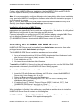
To install the KLMBPLUS Server from the self-extracting archive, run the 28010xxx.EXE
and proceed as directed by the KLMBPLUS Server Setup program.
To install the KLMBPLUS Server from CD or distribution disks, on MS Windows:
1. Insert the CD with Klinkmann Software into CD drive or insert the KLMBPLUS
Server Disk1 into a floppy drive A: or B:.
2. Select the Run command under the Start menu.
3. Run STARTUP.EXE if installing from CD or SETUP.EXE if installing from
distribution disks (floppies).
4. If installing from CD: select “Protocol Servers (DDE, SuiteLink, OPC)”, find
“KLMBPLUS DDE Server” and click on “Setup…”.
5. Proceed as directed by the KLMBPLUS Server Setup program.
When installation is finished, the subdirectory specified as a folder where to install the
KLMBPLUS Server files will contain the following files:
KLMBPLUS.EXE
The KLMBPLUS DDE Server Program. This is a Microsoft
Windows 32-bit application program.
KLMBPLUS DDE Server Ver 1.x, User Manual Rev 1.6
280xxm16
4
KLINKMANN Automation KLMBPLUS DDE Server
KLMBPLUS.HLP
The KLMBPLUS DDE Server Help file.
KLMBPLUS.CFG
An example configuration file.
WWCOMDLG.DLL
Dynamic Link Library necessary for KLMBPLUS DDE Server.
LICENSE.TXT
Klinkmann Automation software license file.
To uninstall the KLMBPLUS DDE Server, start Control Panel, select “Add/Remove
Programs” and select “KLMBPLUS DDE Server” from the list of available software
products. Click on “Add/Remove…” and proceed as directed by the UnInstallShield
program.
Notes:
1. The HASP key is needed for full time running of KLMBPLUS DDE Server. The HASP
Driver setup is performed during the Server setup. Without HASP Driver installed the
Server will run only 1 hour (with all features enabled).
Configuring the KLMBPLUS Server
Once the DDE Server has been installed, a small amount of configuration is required.
Configuring the Server automatically creates a configuration file named,
KLMBPLUS.CFG. This file stores the configuration information for the adapter card
settings and all of the topic definitions.
The configuration file is automatically saved to the directory in which the DDE Server is
installed unless a different directory is specified via the DDE Server Settings... command.
To access the commands used for the various configurations, open the /DDE Server
Settings Menu
KLMBPLUS DDE Server Ver 1.x, User Manual Rev 1.6
280xxm16
5
KLINKMANN Automation KLMBPLUS DDE Server
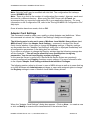
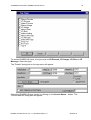
DDE Server Settings Command
A number of parameters that control the internal operation of the Server can be set. In
most cases, the default settings for these parameters provide good performance and do
not require changing. However, they can be changed to fine-tune the Server for a specific
environment.
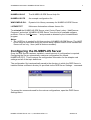
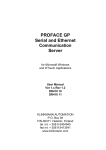
To change the Server's internal parameters, invoke the DDE Server Settings...
command. The "DDE Server Settings" dialog box will appear:
The following describes each field in this dialog box:
Protocol Timer Tick
Enter the frequency (in milliseconds) that the Server is to check for data to process. This
should be approximately two to four times faster than the fastest rate desired to update
data from the equipment.
NetDDE being used
Select this option if you are networking using NetDDE.
.
Configuration File Directory
This field displays the drive\directory into which the Server will save the current
configuration file. To save the configuration file to a different directory, enter the path for
that directory in this field.
KLMBPLUS DDE Server Ver 1.x, User Manual Rev 1.6
280xxm16
6
KLINKMANN Automation KLMBPLUS DDE Server
Note: Only the "path" may be modified with this field. The configuration file is always
named KLMBPLUS.CFG.
Note: There is no limit to the number of configuration files created. However, each must
be saved in a different directory. When using the DDE Server with InTouch, we
recommend that you save the configuration file in your application directory. For more
information on the Configuration File, refer to the "Saving KLMBPLUS Configuration File "
Help topic.
Once all entries have been made, click on OK.
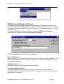
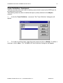
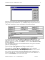
Adapter Card Settings
This command is used to create new, modify or delete Adapter card definitions. When
this command is invoked, the "Adapter Card Settings" dialog box will appear.
The following note is relevant in case of Modicon Local Netlib Library drivers (not
MBX drivers): When the Adapter Card Settings... command is invoked- the Server
firstly checks whether it has rights to change the Registry settings. If Registry settings
are accessible then the "Adapter Card Settings" dialog box is displayed immediately and
all configuration parameters in the dialog box are available.
If you have no privileges to change the Registry settings then the following message box
will be displayed: ” You will not be allowed to save modifications to registry
parameters. You do not have Registry update privileges.”
In this case the Server is useful only if Kernel Mode Device Drivers are previously
correctly configured (and Registry contains correct settings). For more information refer
to the chapter Adapter Card Settings without Administrator Privileges.
The following section refers to all users in case of MBX drivers as well as to users that log
on to MS Windows with Administrator privileges or users with assigned rights to change
the Registry settings in case of Modicon Local Netlib Library drivers.
When the "Adapter Card Settings" dialog box appears - Click on New… to create a new
or click on Modify to examine the characteristics of the selected Card.
KLMBPLUS DDE Server Ver 1.x, User Manual Rev 1.6
280xxm16
7
KLINKMANN Automation KLMBPLUS DDE Server
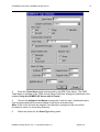
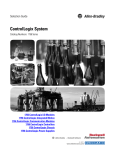
The "KLMBPLUS Adapter Card Settings " dialog box will appear:
The following describes each dialog field in this dialog box:
Card Name
This field is used to enter the unique name for the Adapter card. (This name will be used
in topic definitions to associate a topic with a specific Adapter card).
Adapter Number
Select the Adapter Number assigned to SA85 (or PCI85) card.
Note: With Local Netlib Library drivers, when using KLMBPLUS DDE Server with one
SA85 Adapter card installed in the computer, Adapter Number should be 0.
If additional Adapter card is attached then it’s number should be 1.
Memory Base Address
This dialog option is relevant only with Local Netlib Library drivers.
Select the memory address set in the "memory window" switch on the SA85 Adapter card
when it was installed. The value to be entered here is the segment or paragraph
address, not the byte address. For example, if the memory window was assigned to
D0000 - select D000 in this field.
Reserved Channels
This dialog option is relevant only with Local Netlib Library drivers.
Select a number between 0 and 7. This is the number of Modbus Plus channels reserved
for other programs to use. It is not recommended to use the Modbus Plus DDE Server
and the Modsoft programming software at the same time with a single SA85 card.
However, if you choose to run Modsoft and the DDE Server at the same time, be sure
you reserve a channel for Modsoft.
KLMBPLUS DDE Server Ver 1.x, User Manual Rev 1.6
280xxm16
8
KLINKMANN Automation KLMBPLUS DDE Server
Reply Timeout
Enter the amount of time (in seconds) that all PLCs connected via this Adapter card will
be given to reply to commands from the DDE Server.
Note: This time-out is sustained only when the PLC fails to respond. When the PLC is
responding normally, there is no penalty. The default value of three seconds should be
sufficient for most configurations.
Reply Timeout Globals
Enter the amount of time (in seconds) to reply for reading Global Data from the Modbus
Plus network.
Driver Type
Select Netlib/Netbios option if Modicon Local Netlib Library drivers are installed on
computer.
Select Netlib/MBX option if Cyberlogic’s MBX drivers are installed on computer.
Once all entries have been made, select OK to process the configuration for the Adapter
card.
Select Done in the "Adapter Card Settings" dialog box when Adapter card configuration
has been performed.
When Done is selected the Server updates it's configuration file.
If Modicon Local Netlib Library drivers (not MBX!) are used to access the Modbus Plus
network then the Server updates (if necessary) Adapter card's parameters in REGISTRY
(Kernel Mode Device Driver settings). If it is necessary to reboot the computer to activate
changes of Kernel Mode Device Driver settings then the message box appears with the
following message: "You must reboot to activate changes you made. Do you want to
reboot now? To restart the computer automatically, select Yes. If you want firstly to
check the contents of Registry - select No, then check REGISTRY parameters and restart
the computer manually.
Note: Not all parameter changes made in the "KLMBPLUS Adapter Card Settings "
dialog box causes needs to restart the computer.
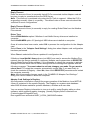
Adapter Card Settings in Registry
All configuration information required for proper operation of the Modicon Local NETLIB
Library is contained in the system Registry. The Registry is a system-wide database
where MS Windows maintains systems hardware, software and user data.
You can access Registry information to view or to edit by using Registry editor or other
software, which supports registry changing. (Usually Registry editor is started from
C:\winnt\system32\regedt32.exe.)
Run regedt32.exe and select HKEY_LOCAL_MACHINE window.
KLMBPLUS DDE Server Ver 1.x, User Manual Rev 1.6
280xxm16
9
KLINKMANN Automation KLMBPLUS DDE Server
Most of the configuration information used by the Kernel Mode Device Driver that is part
of Local NETLIB Library is located directly under the
HKEY_LOCAL_MACHINE\SYSTEM\CurrentControlSet\Services\MBPLUS key in the
Registry.
Each Adapter card has it’s own subkey in the form of Device0 or Device1 and has it’s
own unique settings (subkey Device0 strictly corresponds to Adapter number 0, subkey
Device1 - corresponds to Adapter number 1):
AdapterNumber
Each Adapter card must have a unique adapter card number assigned to it (0 or 1).
Adapter Number corresponds to one you have selected in the "KLMBPLUS Adapter Card
Settings" dialog box.
BusNumber
MS Windows supports systems with multiple buses. This parameter specifies the bus
number for the Adapter card. Use default for this parameter (zero).
DeviceType
The device type identifies the adapter card family used with the library. For Modbus Plus
host interface adapters select "SA85 Family”.
InterruptIRQ
In case of KLMBPLUS operation an Adapter must run in polled mode. IRQ must be set to
0. The Interrupt IRQ jumper must be also set to polled mode on the Adapter card.
MemoryAddress
This parameter specifies the base address set by switches of the Adapter card (example:
D0000). Memory Address corresponds to one you have selected in the "KLMBPLUS
Adapter Card Settings" dialog box.
KLMBPLUS DDE Server Ver 1.x, User Manual Rev 1.6
280xxm16
10
KLINKMANN Automation KLMBPLUS DDE Server
Name
This parameter is used to store the operating system visible name for the device driver
(for example "MbpDrv0"). This name must uniquely identify the driver instance and
cannot be used by any other driver in the system.
NetworkAdapter
This parameter identifies the type of Adapter card to be used. The valid name is: SA85.
PolledMode
In case of KLMBPLUS operation an Adapter must run in polled mode. Set parameter
value to 1.
PollingInterval
This parameter specifies the polling interval in milliseconds that the driver will use when
running in the polled mode. The valid range for the polling interval is 10 - 1000
milliseconds. The recommended value used is 20ms (default).
Slot Number
For all Micro Channel cards the slot number for the Adapter card has to be specified. The
valid slot number starts from one.
Note: Changes will be activated after the computer is rebooted.
Adapter Card Settings without Administrator Privileges
If you do not have privileges to change the Registry settings you can still use the Server
with predefined Kernel Mode Device Drivers settings in Registry.
When opening the "KLMBPLUS Adapter Card Settings " dialog box (see chapter Adapter
Card Settings) you can select Adapter Number and associate a new Card Name to it.
You can configure the number of Reserved Channels as well as the Reply Timeout
values.
Memory Base Address is not accessible! Value you see in this dialog field is not
configuration value. Use Registry editor to check real Adapter settings in Registry.
KLMBPLUS DDE Server Ver 1.x, User Manual Rev 1.6
280xxm16
11
KLINKMANN Automation KLMBPLUS DDE Server
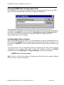
Saving KLMBPLUS Configuration File
If a configuration file does not currently exist in the configuration file directory, the DDE
Server will automatically display the Save Configuration dialog box.
This dialog box displays the path where the Server is going to save the current
configuration file. The path may be changed if necessary. Also, the path can optionally be
recorded in the WIN.INI file by selecting the "Make this the default configuration file"
option. Doing so will allow the Server to find the KLMBPLUS configuration file
automatically each time it is started.
Configuration File Location
When the KLMBPLUS Server starts up, it first attempts to locate its configuration file by,
first checking the WIN.INI file for a path that was previously specified. If the path is not
present in the WIN.INI file, the Server will assume that the current working directory is to
be used.
To start the Server from an application directory configuration file other than the default
configuration file a special switch (/d:) is used. For example, invoke the File/Run
command from the File Manager or Program Manager and enter the following:
KLMBPLUS /d:c:\directoryname
Note: There is no limit to the number of configuration files that may be created, although
each must be in a separate directory.
KLMBPLUS DDE Server Ver 1.x, User Manual Rev 1.6
280xxm16
12
KLINKMANN Automation KLMBPLUS DDE Server
Topic Definition Command
The user provides each node with an arbitrary name which is used as the DDE topic for
all references to the node.
The following steps are taken to define the topics (nodes) attached to the Mbplus
network:
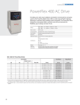
1.
Invoke the Topic Definition... command. The "Topic Definition" dialog box will
appear:
2.
To modify an existing topic, select the topic name and click on Modify. To define a
new topic, click on New. The " KLMBPLUS Topic Definition" dialog box will appear:
KLMBPLUS DDE Server Ver 1.x, User Manual Rev 1.6
280xxm16
13
KLINKMANN Automation KLMBPLUS DDE Server
3.
Enter the Topic Name which corresponds to the DDE Topic Name. (The DDE
Topic Name is entered in the "DDE Access Name Definition" dialog box described in the
chapter Using the KLMBPLUS Server with InTouch.)
4.
Choose the Adapter Card Name to associate it with the topic. (Additional topics
may be associated with the same Adapter Card Name at a later time.)
Note: If this is the first time an Adapter Card has been configured, the user will be
prompted to save it to an existing directory.
5.
Select the option for the Slave Type being used.
KLMBPLUS DDE Server Ver 1.x, User Manual Rev 1.6
280xxm16
14
KLINKMANN Automation KLMBPLUS DDE Server
6.
Enter the Slave Path of the PLC. If intermediate bridges are used between the PC
and the PLC, enter the node IDs of the bridge(s) in order from the PC through all bridges,
ending with the PLC. If multiple IDs are entered, they must be separated by a period (.).
7.
Enable Unsolicited Messages to allow the Server to accept data which PLC
internal program transfers to the host PC. In Channel box associate a Slave Channel
number to listen for Unsolicited messages. This channel number must match the channel
specified in the corresponding MSTR block (see chapter Notes on Accessing
Unsolicited Data) in the internal program of the PLC wishing to transfer data to the host
(PC).
Note: If Unsolicited Messages is checked then the topic's Data execution depends on
Update Interval value configured for current topic. If Update Interval value is zero then
the Server is only looking for data sent by the PLC's internal program and no polling is
processed. If the Update Interval value is non-zero, the Server polls for the data of this
topic in addition to accepting Unsolicited messages.
No data writes are processed for topics waiting for unsolicited data!
Note: Never check Unsolicited Messages if the PLC internal program does not process
Unsolicited Data, otherwise it hardly interrupts the Server data execution!
8.
Select the option for the style the PLC uses to store ASCII strings in its registers.
Note: For more information on the String Variable Styles, refer to the chapter Item/Point
Naming.
9.
Select the option for the Register Type being used.
Note: This selection is relevant only for Register value transmission. If BCD option is
checked then unsigned integers is executed as Binary Coded Decimal (BCD) values.
Option is not relevant for signed integers, long integers, float values and strings, which
are executed in similar way for each Slave Type selection.
10.
Enter the maximum number of consecutive coils to be read at one time. In this
example, the valid Coil Read values can be between 8 and 2000 and must be an even
multiple of 8. If this option is set to zero, then this operation is not available for the
selected Slave Type.
11.
Enter the maximum number of consecutive coils that can be written to at one time.
In this example, the valid Coil Write values can be between 8 and 128 and must be an
even multiple of 8. If this option is set to zero, then this operation is not available for the
selected Slave Type.
12.
Enter the maximum number of consecutive registers to be read at one time. In this
example, the valid Register Read values can be between 1 and 100. If this option is set
to zero, then this operation is not available for the selected Slave Type.
13.
Enter the maximum number of consecutive coils that can be written to at one time.
In this example, the valid Register Write values can be between 1 and 100. If this option
is set to zero, then this operation is not available for the selected Slave Type.
Note: The value represented in this example only applies to the 584/984 Slave Type.
KLMBPLUS DDE Server Ver 1.x, User Manual Rev 1.6
280xxm16
15
KLINKMANN Automation KLMBPLUS DDE Server
Note: The default Coil Read, Coil Write, Register Read and Register Write values are
maximally supported by the KLMBPLUS DDE Server. Reduce values if you suppose that
number of data to be processed in one request is too great and the PLC cannot process
such data quantity in satisfactory speed.
14.
Enter the frequency (in milliseconds) that the Server will read (poll) the
items/points associated with this topic. (Different items/points can be polled at different
rates by defining multiple topic names for the same PLC and setting different updates
rates for each topic.)
Once all entries have been made, click on OK.
KLMBPLUS DDE Server Ver 1.x, User Manual Rev 1.6
280xxm16
16
KLINKMANN Automation KLMBPLUS DDE Server
Using the KLMBPLUS Server with InTouch
To access items/points on Modicon PLCs from InTouch, the following steps (all
performed in WindowMaker) are required:
To define the DDE Access Names in WindowMaker for each node invoke the
/Special/Access Names... command. The "Access Names" dialog box will appear.
Click on Add. The "Add Access Name" Dialog Box will appear:
Note: If Add is selected, this dialog box will be blank when it initially appears. Data has
been entered here to illustrate the entries which are made.
The following fields are required entries when entering a DDE Access Name Definition:
KLMBPLUS DDE Server Ver 1.x, User Manual Rev 1.6
280xxm16
17
KLINKMANN Automation KLMBPLUS DDE Server
Access Name
In the Access Name box type the name you want InTouch to use to this Access Name.
(For simplicity, use the same name that you will use for the Topic Name here.)
Node Name
If the data resides in a network DDE Server, in the Node Name box, type the remote
node's name.
Application Name
Enter the application name, KLMBPLUS, which is the DDE Server used to accessing the
Controller. Do not enter the .exe extension portion of the program name.
Topic Name
Enter the name defined for the topic in KLMBPLUS to identify the node the KLMBPLUS
Server will be accessing.
Note: This will usually be the same as the "Access Name", although, if desired, they may
be different. However, it must be the same name used when the topics were configured
in section Configuring the KLMBPLUS Server.
Which protocol to use
Select the DDE protocol.
When to advise server
Select Advise all items if you want the Server program to poll for all data whether or not
it is in visible windows, alarmed, logged, trended or used in a script. Selecting this option
will impact performance, therefore its use is not recommended.
Select Advise only active items if you want the Server program to poll only points in
visible windows and points that are alarmed, logged, trended or used in any script.
Click OK to accept the new Access Name and close the "Add Access Name" dialog box.
The "Access Names" dialog box will reappear displaying the new Access Name selected
in the list.
Click Close to close the "Access Names" dialog box.
KLMBPLUS DDE Server Ver 1.x, User Manual Rev 1.6
280xxm16
18
KLINKMANN Automation KLMBPLUS DDE Server
Defining the Tag names
To define the Tag names associated with the new "Access Name", invoke the
/Special/Tagname Dictionary... command (in WindowMaker). The "Tagname Dictionary"
dialog box will appear:
Click on New and enter the Tag Name. (The tag name defined here is the name InTouch
will use. The KLMBPLUS Server does not see this name.)
Select the tag type by clicking on the Type button. The "Tag Types" dialog box will
appear:
KLMBPLUS DDE Server Ver 1.x, User Manual Rev 1.6
280xxm16
19
KLINKMANN Automation KLMBPLUS DDE Server
To access KLMBPLUS items, the type must be I/O Discrete, I/O Integer, I/O Real or I/O
Message. Select the type.
The "Details" dialog box for the tag name will appear:
Select the KLMBPLUS topic (node) by clicking on the Access Name... button. The
"Access Names" dialog box will appear:
KLMBPLUS DDE Server Ver 1.x, User Manual Rev 1.6
280xxm16
20
KLINKMANN Automation KLMBPLUS DDE Server
Select the appropriate Access Name and click on Close. (If the Access Name has not
been defined as previously described, click on Add and define the Access Name now.)
The "Details" dialog box will appear displaying the selected Access Name:
For integers and reals fill in the Min EU, Max EU, Min Raw and Max Raw fields. These
fields control the range of values, which will be accepted from the server and how the
values are scaled. If no scaling is desired, Min EU should be equal to Min Raw and Max
EU equal to Max Raw.
Enter the KLMBPLUS item/point name to be associated with this tag name in the Item
field in the "Details" dialog box:
(Refer to the Item (Point) Naming section below for complete details.)
Where applicable, the Use Tag name as Item Name option may be selected to
automatically enter the tag name in this field. Note: The tag name can only be used if it
follows the conventions listed in the Item (Point) Naming section.
Once all entries have been made, click on the Save button (in the top dialog box) to
accept the new tag name. To define additional Tag names click on the New button. To
return to the WindowMaker main screen, select Done.
KLMBPLUS DDE Server Ver 1.x, User Manual Rev 1.6
280xxm16
21
KLINKMANN Automation KLMBPLUS DDE Server
Monitoring the Status of Communication with InTouch
InTouch supports built-in topic names called DDEStatus and IOStatus, which are used to
monitor the status of communication between the Server and InTouch. For more
information on the built-in topic names DDEStatus and IOStatus, see your online
"InTouch Users Guide".
The status of communication between the Server and InTouch can be read into Excel by
entering the following DDE reference formula in a cell on a spreadsheet (in following
example PLC1 is the Topic Name configured for KLMBPLUS Server):
=view|DDEStatus!PLC1
KLMBPLUS DDE Server Ver 1.x, User Manual Rev 1.6
280xxm16
22
KLINKMANN Automation KLMBPLUS DDE Server
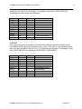
Item (Point) Naming
The DDE Server supports item/point names that are consistent with the point naming
convention used by Modicon PLCs. The Server allows you to select a Slave Type when
you configure the topic definition for the PLC.
The configuration of the types of data can be as follows:
PLC Type
484
584/984
Micro84
6 Digit
Point Type
Range
DDE Tag Type
Access
Coil
Contact
Input Register
Holding Register
Coil
Contact
Input Register
Holding Register
Coil
Contact
Input Register
Holding Register
1-999
1001-1999
3001-3999
4001-4999
Discrete
Discrete
Analog
Analog
Read/Write
Read Only
Read Only
Read/Write
1-9999
Discrete
Read/Write
10001-19999
30001-39999
40001-49999
1-655336
100001-165536
300001-365536
400001-465536
Discrete
Analog
Analog
Discrete
Discrete
Analog
Analog
Read Only
Read Only
Read/Write
Read/Write
Read Only
Read Only
Read/write
Special handling of data from Modicon equipment can be done by using the following
conventions:
SIGNED REGISTERS
The DDE Server normally allows register values in the range of 0 to 65535. Registers
may be treated as 16-bit signed quantities having values from -32,768 to 32,767.
To specify that a register be treated as a signed quantity, append a space and the letter S
to the item name. For example, to indicate that the first Holding Register is signed, enter
"40001 S" for the item name.
LONG INTEGERS
Pairs of registers can be treated as 32-bit signed integers. This is done by appending a
space and the letter L to the item name. For example: 40001 L.
FLOATING POINT
Pairs of registers can be treated as IEEE 32-bit floating-point numbers. This is done by
appending a space and the letter F to the item name. For example: 40001 F.
BITS IN REGISTERS
Individual bits in registers can be read as discrete tags by using the notation rrrr:b.
Where rrrr specifies a valid input register or holding register and b specifies a bit position
between 1 and 16 (1 specifies the most significant bit of the register).
Examples:
40001:1
most significant bit of first holding register
30008:16
least significant bit of an input register
4001:5
5th from the most significant bit of first holding register in a 484
controller.
KLMBPLUS DDE Server Ver 1.x, User Manual Rev 1.6
280xxm16
23
KLINKMANN Automation KLMBPLUS DDE Server
Note: Bits in registers are read-only. The Modbus/Modbus Plus protocol has no
commands to write individual register bits.
Since version v1.05 the Server supports bits in Global area (except Global area of topic
corresponding to the network adapter card.)
EXPLICIT CONVERSIONS
Coils and contacts are treated only as discrete variables.
Registers are normally treated as integers. This can be altered for specific registers by
adding a blank space (using the spacebar) and one of the following to the point type:
L
Long
F
Float
M
Message (ASCII Strings)
MODULO-10000 POINTS
Two or three consecutive registers may be interpreted as a single numeric quantity. In
doing so, each of the component registers must be in the range of 0-9999. For example,
two registers "40001-40002" can represent numbers between 0 and 99999999.
Overflow becomes a possibility when grouping three consecutive registers for
interpretation as a single numeric quantity. The largest number that may be represented
in the PLC with three consecutive Modulo-10000 registers is 999,999,999,999.
Unfortunately, the largest number, which can be contained in ‘integer’ type variable, is
2,147,483,647. The latter number is used by the Server to represent an overflow
condition. Therefore, the maximum usable value represented in three Modulo-10000
registers is 2,147,483,646 (or < 21 >< 4748 >< 3646 >). Any numbers larger than this will
be clamped at 2,147,483,647.
ASCII STRINGS
Multiple consecutive registers (1-100) can be treated as a string of ASCII characters. The
first character of the string is in the high-order 8-bits of the lowest numbered register.
Three options are provided for the representation of variable length strings:
1.
The string may be padded with ASCII spaces (hex 20) - (FULL LENGTH).
2.
The string may be terminated with a zero byte - (C-STYLE).
3.
The length may be stored in the first byte - (PASCAL STYLE).
Strings of ASCII characters can be stored in consecutive registers in a PLC. The number
of registers that are allocated to the storage of an individual string must be fixed.
However, the string contained in those registers can have a variable length up to twice
the number of registers allocated. Strings are stored in Modbus/Modbus Plus registers
from lowest numbered register to the highest and within each register, first the most
significant byte, then the least significant byte. The Modbus/Modbus Plus DDE Server
supports three methods of storing strings of ASCII characters in registers:
FULL LENGTH
If strings are stored in this manner, the string always uses all of the registers allocated. If
the string is shorter than the allocation of registers, it is padded with ASCII space
KLMBPLUS DDE Server Ver 1.x, User Manual Rev 1.6
280xxm16
24
KLINKMANN Automation KLMBPLUS DDE Server
characters (hex 20) to the full length. For example, string item "30001-30010 M"
containing the ASCII string "Wonderware":
30001
30002
30003
30004
30005
30006
30007
30008
30009
30010
MSB
LSB
57
6E
65
77
72
20
20
20
20
20
6F
64
72
61
65
20
20
20
20
20
"Wo"
"nd"
"er"
"wa"
"re"
" "
" "
" " padded to the end
" " with ASCII spaces
" "
C-STYLE
If strings are stored in this manner, the end of the string is marked by a byte of zero
immediately following the last character in the string. This option is so named because
this is the way strings are stored in the "C" programming language. For example, string
item "30001-30010 M" containing the ASCII string "Wonderware":
30001
30002
30003
30004
30005
30006
30007
30008
30009
30010
MSB
57
6E
65
77
72
0
x
x
x
x
LSB
6F
64
72
61
65
x
x
x
x
x
"Wo"
"nd"
"er"
"wa"
"re"
end marked by zero
the remaining
bytes
are
unused
KLMBPLUS DDE Server Ver 1.x, User Manual Rev 1.6
280xxm16
25
KLINKMANN Automation KLMBPLUS DDE Server
PASCAL STYLE
If strings are stored in this manner, the length of the string is denoted by a length byte
which occupies the first byte of the string (MSB of the first register). This option is so
named because this is the way strings are stored in the "Pascal" programming language
(for most compilers). For example: string item "30001-30010 M" containing the ASCII
string "Wonderware":
30001
30002
30003
30004
30005
30006
30007
30008
30009
30010
MSB
LSB
10
6F
64
72
61
65
x
x
x
x
57
6E
77
72
x
x
x
x
x
x
length = 10"W"
"on"
"de"
"rw'
"ar"
"e"
the remaining
bytes
are
unused
ABSOLUTE NOTATION
Absolute item naming conventions are available that are independent of PLC model
numbers. The absolute notation allows accessing of the four Modbus/Modbus Plus data
types, each with an address from 0 to 65535. The item name suffix characters indicate
the data types as follows:
nnnnn DO
(Discrete Output) refers to the same data Modbus/Modbus Plus calls "coils"
(valid range is 0 DO through 65535 DO.)
nnnnn DI
(Discrete Input) refers to the same data Modbus/Modbus Plus calls
"contacts" (valid range is 0 DI through 65535 DI.)
nnnnn IR
(Input Registers) refers to the same data Modbus/Modbus Plus calls "input
registers" (valid range is 0 IR through 65535 IR.)
nnnnn HR
(Holding Registers) refers to the same data Modbus/Modbus Plus calls
"holding registers" (valid range is 0 HR through 65535 HR.)
nnnnn PV
(Process Variable) refers to holding registers but treats them as floating
points and assumes 2 registers per floating point number. The valid range
is 0 PV through 32767 PV.
The IR and HR absolute notations can also be combined with the following conversions:
L (long), F (floating point) or S (signed.) For example:
KLMBPLUS DDE Server Ver 1.x, User Manual Rev 1.6
280xxm16
26
KLINKMANN Automation KLMBPLUS DDE Server
219 HRS
0 IRL
100 HRF
16 bit signed integer
32 bit signed integer
32 bit floating point
GLOBAL DATA
Global Data tags are specified with a G suffix. For example, point "10 G" refers to the
10'th register in the global area for the topic. Valid address range is from 1 G to 32 G.
You can use the G in conjunction with the other data type suffixes. For example, "10 GF"
is acceptable, and specifies that registers 10 and 11 in the global data area are to be
taken together as a floating-point value. This is analogous to the way the tag "40001 F"
specifies registers 40001 and 40002 will be taken together as a floating-point value.
Note: Global data is read from the Modbus Plus "token" rather than via direct
communication with the PLC. The PLC places its global data in the token, then passed
the data amongst all the participants in the network. This data stays in the token even
after a PLC leaves the network. Topics which read global data exclusively from the PLC
(i.e. there are no tags on advise which cause the Server to poll the PLC for data) will
never show STATUS failing, even if the PLC leaves the network. It is recommended to
place at least 1 "keep-alive" tag on advise to prevent this from occurring.
The MBPLUS Server cannot write to the global data of PLCs, and POKEs to global data
tags are not allowed.
For detailed explanation of Global data processing see chapter Notes on Accessing
Global Data.
UNSOLICITED DATA
Unsolicited Data has no special point naming conventions. However, due to the
architecture of the Modicon PLC's, only 4xxxx tags (or 4xxxxx tags in the 6-digit models)
may be written to with unsolicited messages.
For detailed explanation of Unsolicited data processing see chapter Notes on Accessing
Unsolicited Data.
Special write-only DDE Discrete Item SUSPEND may be used to control communication
with a separate topic. If application changes Item's value from 0 to 1 - then
communication with topic is suspended. If Item's SUSPEND value is changed back to 0,
communication with topic is resumed.
Note: When topic is suspended by setting SUSPEND item to 1, the Server rejects all
write values to this topic.
KLMBPLUS DDE Server Ver 1.x, User Manual Rev 1.6
280xxm16
27
KLINKMANN Automation KLMBPLUS DDE Server
Notes on Accessing Global Data
The PLC places its Global data in the token, and then passes the data amongst all the
participants in the network. This data stays in the token even after a PLC leaves the
network. Server can read PLC's Global data if topic with PLC address (slave path) is
activated. Global data can be accessed in local network.
Reading GLOBAL DATA by the Server
To read values from PLC's Global data a topic associated to the PLC should be
activated. To do it check PLC type in option Slave Type (e.g. 584/984). Do not select
Card that corresponds to Adapter card. Set Slave Path of PLC, e.g. 11.0.0.0.0.
Note: A general slave topic is useful for PLC's Global data access.
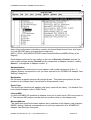
The PLC Internal program must contain MSTR (Master Instruction Block) functions for
Global data writing like presented in Ladder diagram below.
MSTR for Global data writing is represented in example with 3 parameters:
Top Parameter
Top Parameter (Register 400021 - in example) identifies the start address of contiguous
Holding register area containing 5 registers that comprises the Control Block.
Middle Parameter
The register 401001 entered in the middle Parameter is the first in a group of contiguous
holding registers that comprise the data area. For operations that supply data to the
communication processor-such as a Write operation-the Data area is the source of the
data.
Bottom Parameter
The integer value entered in the bottom parameter (direct constant value 00006 - in
example) specifies the length - i.e., the maximum number of registers in the Data area.
The Length must be in the 1...32 range.
Note: Coils and Contact presented in Ladder diagram example are used for MSTR
processing control.
KLMBPLUS DDE Server Ver 1.x, User Manual Rev 1.6
280xxm16
28
KLINKMANN Automation KLMBPLUS DDE Server
Control Block example description
The registers in the MSTR Control Block contain the following information for Global
data Write operation:
Register*
Displayed
(400021)
400022
Function
Operation type
Contents**
5 - identifies MSTR Operation types (Write=5)
Error status
0 - Displays a hex value indicating an MSTR error when
relevant
6 - Specifies the number of registers from the data area
to be sent to the comm processor. The value of the
Length must be <32 and must not exceed the size of
the data area.
0
0 - If this is the second of two local nodes set the high
byte value to 1.
400023
Length
400024
400025
N/A
Routing 1
*) Presented Register Addresses are given for example.
**) Presented values are ready to work example for Global data writing MSTR.
For more detailed explanation of this question see manuals for MODSOFT - Modicon
PLC's programming software.
PLC can write to global buffer <32 words from it's Holding register area. To access these
data a topic associated to a PLC must be activated in the Server and Items 0 G ... 31 G
should be polled.
If PLC internal program is running the MSTR like in presented example then Items 0 G ...
5 G are accessible. Item's 0 G value corresponds to Holding register 401001 (MSTR
Middle Parameter) value in the PLC memory, 1 G value corresponds to Holding register
401002 value, etc.
KLMBPLUS DDE Server Ver 1.x, User Manual Rev 1.6
280xxm16
29
KLINKMANN Automation KLMBPLUS DDE Server
Notes on Accessing Unsolicited Data
Note: Option is not supported with MBX drivers.
Due to the architecture of the KLMBPLUS PLC 4xxxx tags (or 4xxxxx tags in the 6 digit
models) may be transferred to the PC's Adapter card node by the PLC internal program.
Such data is interpreted by the KLMBPLUS Server as UNSOLICITED data. When
processing Unsolicited data the PLC is the master and Server is the slave. In case of
KLMBPLUS Server such data can only be transferred from PLC to the PC but cannot be
requested by PLC from the PC (Server). It means that the Server only accepts data
writing commands sent by the PLC internal program and extracts data values from these
commands. The Server rejects all data request commands.
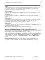
To process Unsolicited Data the PLC internal program must contain MSTR (Master
Instruction Block) function to transfer Holding register contents from PLC to the Adapter
Card's node. The following Ladder diagram contains an example of such MSTR.
MSTR for data transfer is represented in example with 3 parameters:
Top Parameter
Top Parameter (Register 400001 - in example) identifies the start address of contiguous
Holding register area containing 9 registers that comprises the Control Block.
Middle Parameter
The register 400100 entered in the middle Parameter is the first in a group of contiguous
Holding registers that comprise the source data area to be transferred to Adapter card's
node.
Bottom Parameter
The integer value entered in the bottom parameter (direct constant value 00002 - in
example) specifies the length - i.e., the maximum number of registers in the Data area.
The Length must be in the 1... 100 range.
Note: Coils and Contact presented in Ladder diagram example are used for MSTR
processing control. It is recommended to activate MSTR processing in PLC program for
alarm information as well as for transferring data what needs fast update rate.
KLMBPLUS DDE Server Ver 1.x, User Manual Rev 1.6
280xxm16
30
KLINKMANN Automation KLMBPLUS DDE Server
Control Block example description
The registers in the MSTR Control Block contain the following information:
Register*
Displayed
(400001)
Function
Operation type
400002
Error status
400003
Length
400004
Slave device
memory area
Routing 1...5
400005...
400009
Contents**
1 - identifies MSTR Operation types (Write=1).
(Read is not applicable for KLMBPLUS Server
operation! The Server will reject PLC’s requests for
data.)
0 - Displays a hex value indicating an MSTR error when
relevant
2 - Specifies the number of registers to be transferred to
the Adapter card's node. The value of the Length must
be 1...100.
100 - Specifies starting 4x register in the slave to be
read from or written to (e.g. 100=400100, 101=400101)
4 1 0 0 0 - Designates the first...fifth routing path
addresses. In example - value 4 in register 400005 is
Adapter card network Address, value 1 in register
400006 is Slave channel number opened in the Server
(see "KLMBPLUS Topic Definition" dialog box).
*) Presented Register Addresses are given for example.
**) Presented values are ready to work example of MSTR for Unsolicited data
transferring.
In this case PLC Internal program is going to transfer 2 consecutive Holding register
values (starting from 400100) to the PC's Adapter Card with network address 4. Data is
accessible by the Server through Data Slave channel #1.
For more detailed explanation of this question see manuals for MODSOFT - Modicon
PLC's programming software.
It is not recommended to activate more than 8 topics supporting Unsolicited data for one
Adapter card. Otherwise two or more topics will be addressed to the same Data Slave
channel number and that will lead to data interlinking.
To configure the topic processing unsolicited data do the following:
enable Unsolicited Messages check box to allow the Server to accept and
process Unsolicited data,
choose the Channel number the Server is going to listen to for Unsolicited
messages. This channel must match the channel specified in the corresponding MSTR
block of the PLC wishing to transmit Unsolicited data to the Server.
KLMBPLUS DDE Server Ver 1.x, User Manual Rev 1.6
280xxm16
31
KLINKMANN Automation KLMBPLUS DDE Server
If the Update Interval value in "KLMBPLUS Topic Definition" dialog box is non-zero, the
Server will poll for the data in this topic (using standard Data access principles) in addition
to accepting unsolicited messages.
To get values of Unsolicited data a client application must activate corresponding Items
(in example presented in this chapter - Items 40100 and 40101). The Server updates
values of these Items each time when Unsolicited data are received.
Note: After Unsolicited Item is activated by an application the Server immediately reeds
value of an Item through Data Master channels and further waits for Unsolicited
messages.
KLMBPLUS DDE Server Ver 1.x, User Manual Rev 1.6
280xxm16
32
KLINKMANN Automation KLMBPLUS DDE Server
Note: It is not recommended to create more than 8 topics per Adapter card supporting
unsolicited data otherwise two or more topics will be addressed with the same Data Slave
channel number (1...8) and that will lead to data interlinking. The Server does not denied
creation of such topics!
Notes on Improving DDE Server Performance
1. Choosing data access mode.
If the information gathering speed is of essence, for instance Alarms, then a separate
topic associated to the PLC must be created and only few frequently updated Items
should be activated in this topic. Update Interval must be configured to small value.
In this case also the Unsolicited data execution mode may be used instead of standard
data polling mode (see chapter Notes on Accessing Unsolicited Data). If the Server
process Unsolicited data then such data must be transferred by the PLC internal program
so frequently that the Server receives data each time when it looks for Unsolicited Data. If
no Unsolicited Data received then the Server is waiting for them half a second before
leaves a code. It hardly interrupts the Server execution. For this reason not only Alarm
information (when Alarm happens) must be transferred by the PLC internal program but
also "non-Alarm" information must be send time-by-time if no Alarm happens.
If a topic is created to process Unsolicited data then an additional topic must be created
(without Unsolicited Messages support) with the same PLC address and all data writing
must be processed through this topic.
If data access speed has no great importance then standard data polling mode should be
used.
2 The timing problems
The combination of two timing values ("Protocol Timer Tick " value from "DDE Server
Settings" dialog box and "Update Interval" value from "KLMBPLUS Topic Definition"
dialog box) and total number of send messages for each topic determine the
performance of the Server.
In all cases number of messages sent to the network multiplied by "Protocol Timer Tick"
and divided by Channel number the Server operates with (configured in "KLMBPLUS
Adapter Cards Settings" dialog box) must fit into "Update Interval" for all topics. For
example, if there are two topics with 5 messages in one topic and 6 messages in second,
"Update Interval" for both topics is 1000 milliseconds and "Protocol Timer Tick" is 50
milliseconds then total Server work time is
50 * 5 + 50 * 6 = 250 + 300 = 550 milliseconds when accessing data through one
channel. If channel number to operate is 5 (if Reserved Channels number configured in
"KLMBPLUS Adapter Cards Settings" dialog box is 3) then total Server work time is 550 /
5 = 110 milliseconds. In this case if total amount of information sent/received to/from the
MBPLUS network is great and also processing of received data is time consuming then
there would be heavy conditions for other Windows applications (no time to work between
each 50 milliseconds).
KLMBPLUS DDE Server Ver 1.x, User Manual Rev 1.6
280xxm16
33
KLINKMANN Automation KLMBPLUS DDE Server
For a great InTouch applications (with 500 items and more) it is recommended to
increase "Protocol Timer Tick" value and "Update Interval" value - this will allow other
Windows applications run at better timing conditions.
3 Using MBPLUS Network Resources
The KLMBPLUS Server supports access up to 64 data areas in Global buffer and
supports processing of up to 8 Data Master channels and up to 8 Data Slave channels
(for Unsolicited messages) for each Adapter card installed on the PC.
When the Server enters the code it tries to execute maximum number of data channels
per scan and that might put other Windows applications into heavy timing conditions. To
achieve better system timing conditions it is recommended to configure a number of
processed topics/messages per scan. To do it you must set the following Items in
WIN.INI file:
[KLMBPLUS]
MaxUnsolicInTimerTick=5
MaxGlobalInTimerTick=1
MaxChannelInTimerTick=2
If you enter a values as shown in example then every time the Server enters a code it
checks 5 Slave channels for Unsolicited data, then process Global data for 1 PLC and
then process data through 2 Data Master channels. If application has created many
topics then each of Data Master channels is used for a separate topic execution. If only
one topic is created then both channels are used for simultaneously accessing that topic
data.
By manipulating with MaxUnsolicInTimerTic, MaxGlobalInTimerTic and
MaxChannelInTimerTic values optimal KLMBPLUS Server performance can be achieved.
Each system configuration must have unique settings. To access data in local network it
is not reasonably to activate many channels. When data is accessed from remote
networks then the more channels are activated the best timing conditions may be
achieved.
If WIN.INI file does not contain these entries then the Server operates with the default
values:
MaxUnsolicInTimerTic=4
MaxGlobalInTimerTic=1
MaxChannelInTimerTic=8.
4 The using of PLC memory areas
In most cases the KLMBPLUS DDE Server uses MODBUS commands to process data in
MBPLUS network and the maximum number of data items received from the network is
defined by user in the "KLMBPLUS Topic Definition" dialog box.
For example, Register Read Item value is set to 100. In this case maximum of 100
words can be read by one command. The Server uses the following system to create
read commands: memory area's words 0-99 read by the first command, words 100...199
in the second, etc. The data only from one memory area can be read by one read
command. In this case the optimal using of PLC memory is very important - there must
be as few as possible commands sent to the network and it is strongly recommended to
use consecutive memory addresses for DDE items/points - this will considerably improve
the performance of the Server. This choice is recommended if large amount of
consecutive data must be read from few memory areas.
KLMBPLUS DDE Server Ver 1.x, User Manual Rev 1.6
280xxm16
34
KLINKMANN Automation KLMBPLUS DDE Server
5. Other proposals
For great InTouch applications it is recommended to decrease the amount of log
information used for historical trending - historical trends are stored on the disk and
therefore disk read/write operations will take more time as permissible. If there are
problems with the speed of screen redrawing then possible solutions would be the
decreasing of total amount of redrawn information (specially texts) or the increasing of
Server timing values "Protocol Timer Tick" and "Update Interval".
It is recommended to check DumpScreen option in the Server’s System Menu (see
chapter Troubleshooting) only for testing of Server's execution, not in case of normal
Server's execution.
Notes on Using Microsoft Excel
Data from KLMBPLUS topics (nodes) may be accessed from Excel spreadsheets. To do
so, enter a formula like the following one into a cell on the spreadsheet.
=KLMBPLUS|topic!item
Sometimes, Excel requires the topic and/or item/points to be surrounded by apostrophes.
In the formula, topic must be replaced with one of the valid topic names defined during
the Server configuration process. Replace item with one of the valid item/point names
described in the Item (Point) Naming chapter.
Reading Values into Excel Spreadsheets
Values may be read directly into Excel spreadsheets by entering a DDE formatted
formula into a cell, as shown in the following examples:
=KLMBPLUS|'PLC1'!'40001'
=KLMBPLUS|'PLC2'!'10 G'
=KLMBPLUS|'PLC3'!'21 IR'
Writing Values to KLMBPLUS Points
Values may be written to the KLMBPLUS Server by creating an Excel macro which uses
the DDE "POKE" Command. The command is entered in Excel as follows:
=INITIATE("KLMBPLUS ","Topic Name")
=POKE(Channel_Id,"Item",Data_Reference)
=RETURN()
For Channel_Id, use the cell reference where the "INITIATE" statement is found.
For Data_Reference, use the cell identification, which contains the "POKE" value.
Some applications have a limited number of channels; therefore, they should be closed
when finished by using a "TERMINATE" statement in the macro. The "TERMINATE"
macro should have sufficient delay to ensure that the "POKE" has been executed. (Refer
to the Excel Manual for further details.)
Improving Excel/DDE Server Performance
KLMBPLUS DDE Server Ver 1.x, User Manual Rev 1.6
280xxm16
35
KLINKMANN Automation KLMBPLUS DDE Server
To improve communication performance between Excel and the DDE Server, the
following lines should be added to the WIN.INI file under the DDE Server heading:
AllowXLTable=1
DDE Server will accept XLTable format initializations from Excel. This will significantly
speed up the initialization of Excel/Server Conversation.
AllowXLTableForPokes=1
DDE Server will accept XLTable format pokes from Excel. This will significantly speed up
the poke operations from Excel.
For example:
[KLMBPLUS]
AllowXLTable=1
AllowXLTableForPokes=1
Troubleshooting
WIN.INI entries
The first time you run the KLMBPLUS DDE Server configuration, most of the items in the
following list will automatically appear in the WIN.INI file. It is usually in the C:\WINDOWS
directory. It is an ASCII file and can be altered manually if you wish with any text editor,
e.g., MS Windows
Note: do not use a program that formats text, such as MS Word or Write unless the file is
saved as a DOS text).
The following is a typical entry for the KLMBPLUS DDE Server:
[KLMBPLUS]
ProtocolTimer=50
RequestTimer=1000
ValidDataTimeout=60000
DDEBlockSize=4096
WriteRetryIndefinitely=0
ConfigurationFile=C:\KLMBPLUS\
MaxUnsoliInTimerTic=4
MaxGlobalInTimerTic=8
MaxChannelInTimerTic=1
WinIconic=0
WinFullScreen=0
WinTop=112
WinLeft=0
WinWidth=200
WinHeight=168
ShowEvents=1
ShowSend=0
ShowReceive=0
ShowErrors=1
MultiWrite=0
SlowPollRetries=2
KLMBPLUS DDE Server Ver 1.x, User Manual Rev 1.6
280xxm16
36
KLINKMANN Automation KLMBPLUS DDE Server
SlowPollInterval=15
ShowAllRejectedWrites=0
ConsecutiveWriteErrors=3
MaxUnsolicInTimerTick=5
MaxGlobalInTimerTick=1
MaxChannelInTimerTick=2
The MultiWrite entry is used to enter the data writing principles for the Server. The
following values can be entered.
(1) If MultiWrite=0 then for each new write value a separate write message is created.
Only one write message is executed per scan. Even if more than one Network data
channel is accessible only one channel will be used to process write message when the
Server enters a code. The Server changes the values in the PLCs in the same sequence
as they are changed in the user (client) application. In this case the data update rate is
low if application changes values very frequently.
(2) If MultiWrite=1 then the same message can be used for the writing of new values into
the consecutive memory addresses for the same memory area (for example, into 40001,
40002, 40003...). Up to 128 consecutive values can be included in the same write
command depending on configured Block I/O Sizes (Coil Write and Register Write) in
the "KLMBPLUS Topic Definition" dialog box (see chapter Topic Definition Command).
The new value can be added only to the end of the last write message (last message in
the list of pending write messages). Therefore some values may be written into the PLC
memory simultaneously even if the client application changes them step-by-step. In this
case the writing speed can be seriously increased. If more than one Data channel is
accessible the Server process more than one write command simultaneously.
For example, the client application sequentially changes the values of following 100
items: 40001, 40002,..., 40100 and the values of following 100 items: 00001, 00002,...,
00100. In this case the Server creates only two write messages to write the new values
for all the changed items. If the values of the same Items are changed in the following
sequence: 40001, 00001, 40002, 00002, 40003, ... then Server creates a separate write
message for the each new write value.
(3) If MultiWrite=2 then Server tries to include the new write value into the some of
previously created messages ignoring the sequence of data changing in the client
application. If more than one Data channel is accessible the Server process more than
one write command simultaneously. Important! If MultiWrite=2 then maximum writing
speed is achieved, but this option is not recommended if data changing sequence is
important for PLC program!
The ConsecutiveWriteErrors entry is used to enter the number of consecutive
unsuccessful write retries for one write command. If after ConsecutiveWriteErrors the
write command still is not executed then write command is deleted from the list of active
(pending) write messages and write is finally rejected. If the total amount of messages in
the list of active write messages exceeds 300 then every write message is performed only
once not taking into account the ConsecutiveWriteErrors value.
KLMBPLUS DDE Server Ver 1.x, User Manual Rev 1.6
280xxm16
37
KLINKMANN Automation KLMBPLUS DDE Server
The ShowAllRejectedWrites option is useful when communication with a separate topic
(topics) is suspended by Item SUSPEND (see chapter Item (Point) Naming) and the
Server rejects each write to this topic (topics). If ShowAllRejectedWrites = 1 then
information about each rejected write value is displayed by the Server. If
ShowAllRejectedWrites = 0 then the Server rejects each write to the suspended topics
without logging any information.
SlowPollRetries and SlowPollInterval
The SlowPollRetries entry is used to enter the number of consecutive error retries for
one topic (PLC). If after SlowPollRetries there is still no successful response from PLC,
then this topic is changed to slow poll mode. The SlowPollInterval entry is used to enter
the slow poll mode update interval (in seconds).
For example, the following entries can be used to specify that slow poll mode 2 minutes
will start after 3 consecutive unsuccessful retries:
SlowPollRetries=3
SlowPollInterval=120
The MaxUnsolicInTimerTic entry is used to enter the number of Data Slave channels
the Server will check for Unsolicited messages each time when enter a code. Valid values
are 1...8.
The MaxGlobalInTimerTic entry is used to enter the number of Topics for which the
Server will process Global data each time when enter a code. Valid values are 1...8.
The MaxChannelInTimerTic entry is used to enter the number of Data Master channels
the Server tries to process each time when enter a code. Valid values are 1...8.
Note: Real number of processed Data channels per scan also depends on created topic
number, activated Item number, reserved channel number as well as free channel
number in current moment. Neither the same Data Slave channel nor Data Master
channel nor Global data area are processed twice per scan.
The default values (they are used if WIN.INI file and do not contain these entries) are the
following: MultiWrite=0, ConsequtiveWriteErrors=3, ShowAllRejectedWrites=0,
SlowPollRetries=2, SlowPollInterval=15, MaxUnsolicInTimerTick=5,
MaxGlobalInTimerTick=1 and MaxChannelInTimerTick=2.
Troubleshooting menu
The following debugging choices are appended to the Server’s System Menu (the menu
that appears when you click on the “-” box in the upper left hand corner of the Server
window):
Suspend Protocol / Resume Protocol - these choices permit you to turn protocol
processing on and off, what means that you can suspend access to the PLC.
Show Send - if checked then all outgoing user data is displayed in hexadecimal format.
Show Receive - if checked then all incoming user data is displayed in hexadecimal
format.
KLMBPLUS DDE Server Ver 1.x, User Manual Rev 1.6
280xxm16
38
KLINKMANN Automation KLMBPLUS DDE Server
Show Errors - if checked then all information about errors is displayed.
ShowEvents- if checked then Server logs the information about situations when the total
number of active (pending) write messages exceeds 300. It may happen when the Server
has timing problems when executing write commands. When such warnings appear then
it is recommended to modify the Server timing settings or to reduce the total amount of
write data in the client application. Otherwise the possibility of loosing write data
increases.
Information about suspended and resumed topics is displayed if ShowEvents is
checked.
ShowBadWrites- if checked then the Server displays information about all situations
when data write commands are not executed successfully and after
ConsecutiveWriteErrors retries the write is rejected and write message is deleted from
list of active (pending) write messages. This option (if checked) is effective even if other
error logging is stopped.
Verbose
- if checked then all information about errors (except errors indicated in
other choices) is displayed. This option is useful for getting additional information about
error situations when processing Global data as well as data accessible through Data
Master channels:
VerboseUnsol
- if checked then all information about errors (except errors indicated
in other choices) is displayed. This option is useful for getting additional information about
error situations when processing data accessible through Data Slave channels:
When this option is checked simultaneously with the option Show Errors then outgoing
user data as well as incoming user data is displayed in addition to the error report. For
some types of errors the Server gives explanation of possible error reason.
If client application closes communication with a topic then the Server immediately
deletes all this topic's messages from message lists. If write messages are still in the list
of active (pending) messages these write messages are deleted not trying to perform
them. If Verbose option is checked simultaneously with the option ShowBadWrites then
information about not performed and deleted write messages is displayed.
Dump - displays all information about Adapter cards, active topics and data items.
DumpScreen- if checked information about active topics and messages is displayed in
KLMBPLUS main window.
All debug (except DumpScreen option) is displayed via the Wonderware Logger, which
must be active for these commands to work.
Warning: if you check Show Send and/or Show Receive debug output grows very fast.
Message strings you see in WWLogger file are not precisely the same the Server process
to MBPLUS network. Strings contain additional information Bytes (Address, CRC) what
allows checking communication.
KLMBPLUS DDE Server Ver 1.x, User Manual Rev 1.6
280xxm16
39
KLINKMANN Automation KLMBPLUS DDE Server
KLINKMANN AUTOMATION
KLMBPLUS DDE Server
Revision History
Aug 97
Oct 97
Sep 2000
Nov 2001
Mar 2002
Jan 2003
Jan 2003
Rev 1.0
Rev 1.1
Rev 1.2
Rev 1.3
Rev 1.4
Rev 1.5
Rev 1.6
First Release
Minor modifications in manual text
Bit support for Global data added
Support for PCI85 card with MBX drivers added
Installation from CD information added
Minor modifications in manual text
Reply Timeout Global added. SlowPollRetries added
KLMBPLUS DDE Server Ver 1.x, User Manual Rev 1.6
280xxm16