1
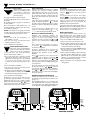
MADE IN
Digital Pressure Gauges
DPG3500, DPG5500, and DPG5600
INSTRUCTION
SHEET
M4094-0606
DPG5500,
DPG5600
Shop online at: omega.com e-mail: [email protected]
For latest product manuals: omegamanual.info
DPG3500
DPG5500
DPG5600
DPG3500
Battery Powered, Min/Max/Zero, NEMA 4X Housing
Battery Powered, Min/Max/Zero
Battery Powered, Min/Max/Zero, Display Backlighting
Ranges and Resolution
Batteries & Battery Life
Resolution is fixed as indicated in table
Ranges in Bold are standard. Contact Omega Engineering for other ranges listed below.
abs: Absolute reference (normally reads atmospheric pressure, reads zero at full vacuum)
vac: Vacuum gauge, minus sign not used unless specified
DPG3500 and DPG5500
2 AA alkaline, approx. 2000 hours
DPG5600
2 AA alkaline, approx. 150 to 1500 hrs depending
on backlight usage
–30.00 inHg/15.00 psig
–30.0 inHg/100.0 psig
–30.0 inHg/200.0 psig
3.000 psig
5.000 psig
15.00 psi abs
15.00 psig vac
±15.00 psig
15.00 psig
30.00 psi abs
30.00 psig
60.00 psig
100.0 psi abs
100.0 psig
200.0 psig
300.0 psig
500.0 psig
1000 psig
2000 psig
3000 psig
5000 psig
6.000 inHg
10.00 inHg
30.00 inHg abs
30.00 inHg vac
±30.00 inHg
30.00 inHg
60.00 inHg abs
60.00 inHg
120.0 inHg
200.0 inHg abs
200.0 inHg
50.00 oz/in2
80.0 oz/in2
240.0 oz/in2 abs
240.0 oz/in2 vac
±240.0 oz/in2
240.0 oz/in2
85.0 inH2O
140.0 inH2O
400.0 inH2O abs
400.0 inH2O vac
±400 inH2O
400.0 inH2O
850 inH2O
7.000 ftH2O
12.00 ftH2O
35.00 ftH2O
70.00 ftH2O
140.0 ftH2O
230.0 ftH2O
480.0 ftH2O
150.0 mmHg
260.0 mmHg
760.0 mmHg abs
760.0 mmHg vac
760.0 mmHg
1600 mmHg abs
1600 mmHg
760.0 torr abs
1600 torr abs
2100 mmH2O
3500 mmH2O
200.0 cmH2O
350.0 cmH2O
1000 cmH2O
2100 cmH2O
200.0 mbar
350.0 mbar
1000 mbar abs
1000 mbar vac
±1000 mbar
1000 mbar
2000 mbar abs
2000 mbar
4000 mbar
1.000 bar abs
1.000 bar vac
±1.000 bar
1.000 bar
2.000 bar abs
2.000 bar
4.000 bar
7.000 bar abs
7.000 bar
14.00 bar
20.00 bar
35.00 bar
70.00 bar
140.0 bar
200.0 bar
350.0 bar
20.00 kPa
35.00 kPa
100.0 kPa abs
100.0 kPa vac
±100.0 kPa
100.0 kPa
200.0 kPa abs
200.0 kPa
400.0 kPa
700.0 kPa abs
700.0 kPa
1500 kPa
2000 kPa
3500 kPa
5000 kPa
3.500 MPa
7.000 MPa
14.00 MPa
20.00 MPa
35.00 MPa
1000 g/cm2 abs
1000 g/cm2
2100 g/cm2 abs
2100 g/cm2
1.000 kg/cm2 abs
1.000 kg/cm2 vac
±1.000 kg/cm2
1.000 kg/cm2
2.000 kg/cm2 abs
2.000 kg/cm2
4.000 kg/cm2
7.000 kg/cm2 abs
7.000 kg/cm2
14.00 kg/cm2
20.00 kg/cm2
35.00 kg/cm2
70.00 kg/cm2
140.0 kg/cm2
200.0 kg/cm2
350.0 kg/cm2
1.000 atm abs
±1.000 atm
1.000 atm
4.000 atm
7.000 atm
14.00 atm
20.00 atm
35.00 atm
70.00 atm
135.0 atm
200.0 atm
340.0 atm
Low Battery Indication
Low battery symbol on display when batteries
must be replaced
Dimensions (see drawing on next page)
DPG3500
3.5" W x 3.0" H x 2.0" D NEMA 4X housing
Add approx. 0.75" to height for pressure fitting
DPG5500 and DPG5600
3.38" W x 2.88" H x 1.65" D housing
Add approx. 0.75" to height for pressure fitting
Weight (approximate)
Gauge:
9 ounces
Shipping weight: 1 pound
Material & Color
DPG3500
Light gray ABS/polycarbonate NEMA 4X case,
rear gasket, polycarbonate label
DPG5500 and DPG5600
Extruded aluminum case, light gray epoxy
powder coated, black ABS/polycarbonate bezel,
front and rear gaskets, polycarbonate label
Connection Size
/4" NPT male
1
Sensor Material
All wetted parts are 316 stainless steel
Controls & Functions
Overpressure
All Models:
DPG5600:
2 times sensor range
3000 psig range & metric equivalents: 5000 psig
5000 psig range & metric equivalents: 7500 psig
112.5% out-of-range display: i – – – or i –.–.–.–
depending on model
Front pushbutton turns gauge on or off and cycles through functions
Press pushbutton to activate 1 minute backlighting when gauge is on
Function
Pushbutton
Prompt (Release Button)
Result
On
Zero
Hi Reading
Lo Reading
Exit Hi/Lo
Clear Hi/Lo
Clear Zero, Off
Press 1 sec
Press/hold
Press/hold
Press/hold
Press/hold
Press/hold
Press/hold
Gauge Range/Display Test
oooo
HI
Lo
AP
HI / LO / AP ☞ Cir
HI / LO / AP ☞ Cir ☞ OFF
Actual Pressure
Zeroed Actual Pressure
HI & max. reading
Lo & min. reading
Actual Pressure
Actual Pressure
Clear Zero, Gauge Off
Accuracy (linearity, hysteresis, repeatability)
Calibration
±0.25% of full scale ±1 least significant digit
Internal calibration pushbuttons, non-interactive
zero, midpoint, span, ±10% range
Display (update rate, type, size)
3 readings per second nominal update rate
4 digit LCD, 0.4" digit height
5 character 0.25" H alphanumeric display
DPG5600: Red LED backlight. Backlighting may
not be visible under bright lighting conditions.
Burst Pressure
4 times sensor pressure rating, or 10,000 psi,
whichever is less
Storage Temperature
–40 to 203°F (–40 to 95°C)
Operating Temperature
–4 to 185°F (–20 to 85°C)
Compensated Temperature
Shutoff
32 to 158°F (0 to 70°C)
See gauge rear label, last character of model
number
-5:
5 minute auto shutoff (standard)
-NS: No auto shutoff, on/off via front pushbutton
Temperature Stability
±0.5% span typical, ±1% span max. 0 to 82°C
DPG3500, DPG5500, and DPG5600 Series
Installation and Precautions
Install or remove gauge using
wrench on hex fitting only. Do
not attempt to tighten by
turning housing or any other
part of the gauge.
CAUTION:
See gauge rear label for pressure range!
Use fittings appropriate for the pressure range of
the gauge.
Do not apply vacuum to gauges not specified for
vacuum operation.
Due to the hardness of 316 stainless steel, it is
recommended that a thread sealant be used to
ensure leak-free operation.
NEVER insert objects into the gauge port or blow
out with compressed air. Permanent damage not
covered by warranty will result to the sensor.
Power-Up
1. Press and hold the
approximately 1 second.
pushbutton
for
2. The full-scale range is indicated and the
display segments are tested.
3. The actual pressure is displayed.
NOTE:
Power-Up With Display Zero
This feature is only used with Gauge
reference models. Absolute reference
gauges do not use the pushbutton
zero feature since they read atmospheric
pressure under normal conditions.
Normal Operation
Shut-Down
Following the start-up initialization, the display
indicates the pressure reading updated
approximately 3 times per second. The auto
shutoff timer starts when the gauge is powered
up or whenever the button is pushed, unless the
gauge was ordered without an auto shutoff time
(-NS option).
To shut off the gauge manually at any time, press
and hold the pushbutton until the display
indicates OFF (about 5 seconds) and then
release.
If excessive vacuum is applied to a pressure-only
gauge, the display will indicate – E r r until the
vacuum is released. Applying vacuum to a gauge
designed for pressure may damage the pressure
sensor.
Battery Replacement
Minimum and Maximum Readings
A low battery indication will be shown in the
upper left-hand corner of the display when the
battery voltage falls sufficiently. The battery
should be replaced soon after the indicator
comes on or unreliable readings may result.
Minimum and maximum readings are
continuously stored and updated whenever
gauge is on. The stored readings can be
manually cleared if desired. The HI and LO
memory is also cleared whenever the gauge is
off.
1. Remove the screws on the back of the unit.
2. Remove batteries by lifting up the positive end
of the battery (opposite the spring) taking care
not to bend the battery holder spring.
Press and hold the pushbutton for about 1
second until HI is displayed. The maximum
stored value is displayed.
3. Discard old batteries properly, DO NOT discard
into fire, sources of extreme heat, or in any
other hazardous manner.
After HI is displayed, press and hold the
pushbutton again for about 1 second until LO is
displayed. The minimum stored value is
displayed.
After LO is displayed, press and hold the
pushbutton again for about 1 second until AP
(Applied Pressure) is displayed. The HI and LO
memory is not erased and the gauge returns to
normal operation with the display indicating the
current pressure.
2. Press and hold the pushbutton.
Press and continue to hold the pushbutton until
the display indicates C i r H i / L o (about 3
seconds total) and then release the pushbutton.
Both HI and LO values are cleared and the
gauge returns to the normal mode and displays
the current pressure.
4. Continue to press the pushbutton until o o o o
is displayed and then release the button. This
indicates that the gauge has been zeroed.
If the gauge was ordered without auto shutoff (NS option) it will stay on until manually shut off or
until the batteries are depleted. Turn gauge off
when not in use to conserve battery life.
If excessive pressure is applied (112.5% over
range), an out-of-range indication of i – – – or i
–.–.–.– will be displayed depending on model.
1. Be sure the gauge port is exposed to normal
atmospheric pressure and no pressure is
applied. The zeroing function is only activated
at each power-up and the stored zero
correction is erased when the gauge is shut
off.
3. The full-scale range is indicated and the
display segments are tested.
For gauges with auto shutoff, the display
indicates OFF five seconds prior to auto shutoff.
The pushbutton can be pressed to keep the
gauge on. The auto shutoff and backlight (if
equipped) timers are reset whenever the
pushbutton is pressed and released.
4. Always replace both batteries at the same time
with high quality alkaline batteries. Install
batteries with correct orientation. The negative
(flat) end of each battery should be inserted
first facing the battery holder spring.
6. Replace the back cover, including the rubber
sealing gasket.
DPG5600 with Display Backlighting
5. The actual pressure is displayed.
Attempting to zero the gauge with pressure
greater than approximately 3% of full-scale
applied will result in an error condition, and the
display will alternately indicate E r r 0 and the
actual measured pressure. The gauge must be
powered down to reset the error condition.
Display backlighting can be tur ned on by
momentarily pressing the button whenever the
gauge is on.
The backlighting will turn on for one minute and
then automatically shut off. This also restarts the
auto shutoff timer. The display backlighting will
not be apparent under bright lighting conditions.
3.0"
X X X88
XX
888
2.88"
X X X88
XX
888
2
Turn at
hex
fitting
only!
Omega Engineering / Made in USA
0.75"
/4"NPT
1
DPG3500
2
0.75"
/4"NPT
2.0"
Turn at
hex
fitting
only
Omega Engineering / Made in USA
1
3.5"
2
1.65"
3.38"
DPG5500, DPG5600
DPG3500, DPG5500, and DPG5600 Series
CAUTION:
Calibration Precautions
4.
Install or remove gauge using wrench on hex fitting only.
Do not attempt to tighten or loosen by turning housing or
any other part of the gauge.
See gauge rear label for pressure range!
Use fittings appropriate for the pressure range of the gauge. The gauge
range is indicated on the rear label and is indicated on the display during
power-up.
Do not apply vacuum to gauges not designed for vacuum operation.
Due to the hardness of 316 stainless steel, it is recommended that a thread
sealant be used to ensure leak-free operation.
NEVER insert objects into the gauge port or blow out with compressed air.
Permanent damage not covered by warranty will result to the sensor.
These products do not contain user serviceable parts. Contact Omega
Engineering for calibration, service, or refurbishment.
NOTE:
1.
Calibration Preparation
a. Calibration should only be performed by qualified individuals using
appropriate calibration standards and procedures.
b. The calibration equipment should be at least four times more accurate
than the gauge being calibrated.
c. Remove the screws on the back of the unit and remove cover.
d. It is good practice to install fresh batteries before calibrating batterypowered gauges.
e. Allow the gauge to equalize to normal room temperature before
calibration.
2.
Entering the Calibration Mode
a. Note the locations of the two internal calibration pushbuttons marked
UP and DOWN. These buttons are disabled unless the gauge is in
calibration mode.
b. With the gauge off, press and hold the DOWN calibration button, and
also press the front button to power up the gauge in calibration mode.
5.
3.
UP
Calibration Mode Functions
a. The display first indicates the gauge’s full-scale pressure range, tests all
display segments, and then indicates CAL to indicate that the gauge is
in the calibration mode. Release all pushbuttons.
b. The display will then indicate the current pressure reading, updating
approximately 3 times per second. The gauge will remain in the
calibration mode until powered down or reset manually. While in the
calibration mode, the shutoff timer, One Touch Zero (gauge reference
models only), Min/Max (for applicable models) are all disabled, and the
calibration pushbuttons are active.
c. Each press of the UP or DOWN button makes a small correction, which
may not always be indicated on the digital display. Press and hold the
pushbutton for one second or longer to make larger continuous
corrections. The display of the gauge being calibrated is adjusted to
match the calibrator’s setting or readout.
d. If the batter y pack is unplugged or the power removed during
calibration, calibration settings will not be saved.
Absolute Reference Gauges (3 Points)
a. Apply full vacuum to the gauge. The vacuum pump must be able to
produce a vacuum of 10 microns (0.01 torr or 10 millitorr) or lower. The
character display will alternate between ZERO and CAL. Press the UP
and DOWN buttons to obtain a display indication of zero.
b. Apply full-scale pressure. The character display will alternate between
+SPAN and CAL. Press the UP and DOWN buttons to obtain a
display indication equal to full-scale pressure.
c. Apply 50% of full-scale pressure. The character display will alternate
between +MID and CAL. Press the UP and DOWN buttons to obtain a
display indication equal to 50% of full-scale pressure.
6.
Bipolar (±) and –30inHg/15psig Compound Ranges
(5 Points)
a. With the gauge port open to atmosphere, the character display will
alternate between ZERO and CAL. Press the UP and DOWN buttons
to obtain a display indication of zero.
b. Apply full-scale positive pressure. The character display will alternate
between +SPAN and CAL. Press the UP and DOWN buttons to obtain
a display indication equal to full-scale pressure.
c. Apply 50% of full-scale positive pressure. The character display will
alternate between +MID and CAL. Press the UP and DOWN buttons to
obtain a display indication equal to 50% of full-scale pressure.
d. Apply full vacuum. The character display will alternate between -SPAN
and CAL. Press the UP and DOWN buttons to obtain a display
indication equal to the full vacuum reading.
e. Apply 50% of the full-scale vacuum range (for example, –7.4 psi for a
±15 psi gauge). The character display will alternate between -MID and
CAL. Press the UP and DOWN buttons to obtain a display indication
equal to 50% of full-scale vacuum.
7.
DOWN
Gauge Reference Gauges (3 Points)
a. With the gauge port open to atmosphere, the character display will
alternate between ZERO and CAL. Press the UP and DOWN buttons
to obtain a display indication of zero.
b. Apply full-scale pressure. The character display will alternate between
+SPAN and CAL. Press the UP and DOWN buttons to obtain a
display indication equal to full-scale pressure.
c. Apply 50% of full-scale pressure. The character display will alternate
between +MID and CAL. Press the UP and DOWN buttons to obtain a
display indication equal to 50% of full-scale pressure.
–30inHg/100psig and –30inHg/200psig Compound
(4 Points)
a. With the gauge port open to atmosphere, the character display will
alternate between ZERO and CAL. Press the UP and DOWN buttons
to obtain a display indication of zero.
b. Apply full-scale positive pressure. The character display will alternate
between +SPAN and CAL. Press the UP and DOWN buttons to obtain
a display indication equal to full-scale pressure.
c. Apply 50% of full-scale positive pressure. The character display will
alternate between +MID and CAL. Press the UP and DOWN buttons to
obtain a display indication equal to 50% of full-scale pressure.
d. Apply full vacuum. The character display will alternate between -SPAN
and CAL. Press the UP and DOWN buttons to obtain a display
indication equal to the full vacuum reading.
8.
Exit Calibration Mode and Verify Calibration
a. Battery-powered gauges: Exit the calibration mode and save the
calibration data by pressing and holding the front button until the display
indicates OFF.
b. Verify pressure indications at 0%, 25%, 50%, 75%, and 100% of full
scale.
c. Replace the rear cover and screws, taking care not to pinch the power
leads between the case and the rear cover.
3
Servicing Europe:
OMEGAnet ® Online Service
www.omega.com
Internet e-mail
[email protected]
Servicing North America:
USA:
ISO 9001 Certified
Canada:
One Omega Drive, Box 4047
Stamford CT 06907-0047
Tel: (203) 359-1660
e-mail: [email protected]
FAX: (203) 359-7700
976 Bergar
Laval (Quebec) H7L 5A1, Canada
Tel: (514) 856-6928
FAX: (514) 856-6886
e-mail: [email protected]
Benelux:
Postbus 8034, 1180 LA Amstelveen, The Netherlands
Tel: +31 (0)20 3472121
FAX: +31 (0)20 6434643
Toll Free in Benelux: 0800 0993344
e-mail: [email protected]
Czech Republic:
Frystatska 184, 733 01 Karviná, Czech Republic
Tel: +420 (0)59 6311899
FAX: +420 (0)59 6311114
Toll Free: 0800-1-66342
e-mail: [email protected]
France:
11, rue Jacques Cartier, 78280 Guyancourt, France
Tel: +33 (0)1 61 37 2900
FAX: +33 (0)1 30 57 5427
Toll Free in France: 0800 466 342
e-mail: [email protected]
Germany/Austria: Daimlerstrasse 26, D-75392 Deckenpfronn, Germany
Tel: +49 (0)7056 9398-0
FAX: +49 (0)7056 9398-29
Toll Free in Germany: 0800 639 7678
e-mail: [email protected]
For immediate technical or application assistance:
USA and Canada: Sales Service: 1-800-826-6342 / 1-800-TC-OMEGA®
Customer Service: 1-800-622-2378 / 1-800-622-BEST®
Engineering Service: 1-800-872-9436 / 1-800-USA-WHEN®
TELEX: 996404 EASYLINK: 62968934 CABLE: OMEGA
Mexico:
En Espan˜ol: (001) 203-359-7803
FAX: (001) 203-359-7807
United Kingdom: One Omega Drive, River Bend Technology Centre
ISO 9002 Certified
e-mail:[email protected]
[email protected]
Northbank, Irlam, Manchester
M44 5BD United Kingdom
Tel: +44 (0)161 777 6611
FAX: +44 (0)161 777 6622
Toll Free in United Kingdom: 0800-488-488
e-mail: [email protected]
It is the policy of OMEGA to comply with all worldwide safety and EMC/EMI regulations that apply. OMEGA is constantly pursuing certification of its products to the
European New Approach Directives. OMEGA will add the CE mark to every appropriate device upon certification.
The information contained in this document is believed to be correct, but OMEGA Engineering, Inc. accepts no liability for any errors it contains, and reserves the right to alter specifications without
notice. WARNING: These products are not designed for use in, and should not be used for, human applications.
WARRANTY/DISCLAIMER
OMEGA ENGINEERING, INC. warrants this unit to be free of defects in materials and workmanship for a period of 13 months from date of purchase.
OMEGA’s WARRANTY adds an additional one (1) month grace period to the normal one (1) year product warranty to cover handling and
shipping time. This ensures that OMEGA’s customers receive maximum coverage on each product.
If the unit malfunctions, it must be returned to the factory for evaluation. OMEGA’s Customer Service Department will issue an Authorized Return (AR)
number immediately upon phone or written request. Upon examination by OMEGA, if the unit is found to be defective, it will be repaired or replaced
at no charge. OMEGA’s WARRANTY does not apply to defects resulting from any action of the purchaser, including but not limited to mishandling,
improper interfacing, operation outside of design limits, improper repair, or unauthorized modification. This WARRANTY is VOID if the unit shows
evidence of having been tampered with or shows evidence of having been damaged as a result of excessive corrosion; or current, heat, moisture or
vibration; improper specification; misapplication; misuse or other operating conditions outside of OMEGA’s control. Components which wear are not
warranted, including but not limited to contact points, fuses, and triacs.
OMEGA is pleased to offer suggestions on the use of its various products. However, OMEGA neither assumes responsibility for any
omissions or errors nor assumes liability for any damages that result from the use of its products in accordance with information provided
by OMEGA, either verbal or written. OMEGA warrants only that the parts manufactured by it will be as specified and free of defects.
OMEGA MAKES NO OTHER WARRANTIES OR REPRESENTATIONS OF ANY KIND WHATSOEVER, EXPRESS OR IMPLIED, EXCEPT THAT OF
TITLE, AND ALL IMPLIED WARRANTIES INCLUDING ANY WARRANTY OF MERCHANTABILITY AND FITNESS FOR A PARTICULAR PURPOSE
ARE HEREBY DISCLAIMED. LIMITATION OF LIABILITY: The remedies of purchaser set forth herein are exclusive, and the total liability of
OMEGA with respect to this order, whether based on contract, warranty, negligence, indemnification, strict liability or otherwise, shall not
exceed the purchase price of the component upon which liability is based. In no event shall OMEGA be liable for consequential, incidental or
special damages.
CONDITIONS: Equipment sold by OMEGA is not intended to be used, nor shall it be used: (1) as a “Basic Component” under 10 CFR 21 (NRC), used in
or with any nuclear installation or activity; or (2) in medical applications or used on humans. Should any Product(s) be used in or with any nuclear
installation or activity, medical application, used on humans, or misused in any way, OMEGA assumes no responsibility as set forth in our basic
WARRANTY / DISCLAIMER language, and, additionally, purchaser will indemnify OMEGA and hold OMEGA harmless from any liability or damage
whatsoever arising out of the use of the Product(s) in such a manner.
RETURN REQUESTS / INQUIRIES
Direct all warranty and repair requests/inquiries to the OMEGA Customer Service Department. BEFORE RETURNING ANY PRODUCT(S) TO
OMEGA, PURCHASER MUST OBTAIN AN AUTHORIZED RETURN (AR) NUMBER FROM OMEGA’S CUSTOMER SERVICE DEPARTMENT (IN ORDER
TO AVOID PROCESSING DELAYS). The assigned AR number should then be marked on the outside of the return package and on any
correspondence.
The purchaser is responsible for shipping charges, freight, insurance and proper packaging to prevent breakage in transit.
PATENT NOTICE: U. S. Pat. No. 6,074,089; 5,465,838 / Canada 2,228,333; 2,116,055 / UK GB 2,321,712 / Holland 1008153 / Israel 123052 / France
2 762 908 / EPO 0614194. Other patents pending.
FOR WARRANTY RETURNS, please have the following information
available BEFORE contacting OMEGA:
1. Purchase Order number under which the product was PURCHASED,
2. Model and serial number of the product under warranty, and
3. Repair instructions and/or specific problems relative to the product.
FOR NON-WARRANTY REPAIRS, consult OMEGA for current repair charges.
Have the following information available BEFORE contacting OMEGA:
1. Purchase Order number to cover the COST of the repair,
2. Model and serial number of the product, and
3. Repair instructions and/or specific problems relative to the product.
OMEGA’s policy is to make running changes, not model changes, whenever an improvement is possible. This affords our customers the latest in technology and
engineering.
OMEGA is a registered trademark of OMEGA ENGINEERING, INC.
© Copyright 2004 OMEGA ENGINEERING, INC. All rights reserved. This document may not be copied, photocopied, reproduced, translated, or reduced to any electronic
medium or machine-readable form, in whole or in part, without the prior written consent of OMEGA ENGINEERING, INC.
M4094/0606