1
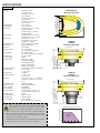
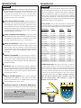
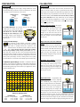
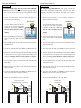
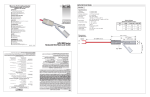
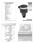
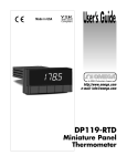
WARRANTY/DISCLAIMER
OMEGA ENGINEERING, INC. warrants this unit to be free of defects in materials and workmanship for a
period of 13 months from date of purchase. OMEGA Warranty adds an additional one (1) month grace
period to the normal one (1) year product warranty to cover handling and shipping time. This ensures
that OMEGA’s customers receive maximum coverage on each product.
If the unit should malfunction, it must be returned to the factory for evaluation. OMEGA’s Customer Service
Department will issue an Authorized Return (AR) number immediately upon phone or written request. Upon
examination by OMEGA, if the unit is found to be defective it will be repaired or replaced at no charge.
OMEGA’s WARRANTY does not apply to defects resulting from any action of the purchaser, including but not
limited to mishandling, improper interfacing, operation outside of design limits, improper repair, or unauthorized modification. This WARRANTY is VOID if the unit shows evidence of having been tampered with or
shows evidence of being damaged as a result of excessive corrosion; or current, heat, moisture or vibration;
improper specification; misapplication; misuse or other operating conditions outside of OMEGA’s control.
Components which wear are not warranted, including but not limited to contact points, fuses, and triacs.
OMEGA is pleased to offer suggestions on the use of its various products. However, OMEGA neither
assumes responsibility for any omissions or errors nor assumes liability for any damages that result
from the use of its products in accordance with information provided by OMEGA, either verbal or written. OMEGA warrants only that the parts manufactured by it will be as specified and free of defects.
OMEGA MAKES NO OTHER WARRANTIES OR REPRESENTATIONS OF ANY KIND WHATS0EVER,
EXPRESSED OR IMPLIED, EXCEPT THAT OF TITLE, AND ALL IMPLIED WARRANTIES INCLUDING ANY
WARRANTY OF MERCHANTABILITY AND FITNESS FOR A PARTICULAR PURPOSE ARE HEREBY DISCLAIMED. LIMITATION OF LIABILITY: The remedies of purchaser set forth herein are exclusive and the
total liability of OMEGA with respect to this order, whether based on contract, warranty, negligence,
indemnification, strict liability or otherwise, shall not exceed the purchase price of the component
upon which liability is based. In no event shall OMEGA be liable for consequential, incidental or special damages.
CONDITIONS: Equipment sold by OMEGA is not intended to be used, nor shall it be used: (1) as a “Basic
Component” under 10 CFR 21 (NRC), used in or with any nuclear installation or activity; or (2) in medical
applications or used on humans. Should any Product(s) be used in or with any nuclear installation or activity,
medical application, used on humans, or misused in any way, OMEGA assumes no responsibility as set forth
in our basic WARRANTY / DISCLAIMER language, and additionally, purchaser will indemnify OMEGA and
hold OMEGA harmless from any liability or damage whatsoever arising out of the use of the Product(s) in
such a manner.
USA:
ISO 9001 Certified
Canada:
omega.com
TM
OMEGA®
OMEGAnet On-Line Service
http://www.omega.com
SM
Internet e-mail
[email protected]
Servicing North America:
One Omega Drive, Box 4047
Stamford, CT 06907-0047
Tel: (203) 359-1660
Fax: (203) 359-7700
e-mail: [email protected]
976 Bergar
Laval (Quebec) H7L 5A1
Tel: (514) 856-6928
FAX: (514) 856-6886
email: [email protected]
For immediate technical or application assistance:
USA and Canada: Sales Service: 1-800-826-6342 / 1-800-TC-OMEGASM
Customer Service: 1-800-622-2378 / 1-800-622-BESTSM
Engineering Service: 1-800-872-9436 / 1-800-USA-WHENSM
Mexico
En Espanol: (001) 203-359-7803
e-mail: [email protected]
FAX: (001) 203-359-7807
[email protected]
Servicing Europe:
Czech Republic:
RETURN REQUESTS / INQUIRIES
Direct all warranty and repair requests/inquiries to the OMEGA Customer Service Department. BEFORE
RETURNING ANY PRODUCT(S) TO OMEGA, PURCHASER MUST OBTAIN AN AUTHORIZED RETURN (AR)
NUMBER FROM OMEGA’S CUSTOMER SERVICE DEPARTMENT (IN ORDER TO AVOID PROCESSING
DELAYS). The assigned AR number should then be marked on the outside of the return package and on
any correspondence.
The purchaser is responsible for shipping charges, freight, insurance and proper packaging to prevent
breakage in transit.
FOR NON-WARRANTY REPAIRS, consult OMEGA
for current repair charges. Have the following
information available BEFORE contacting OMEGA:
1. P.O. number to cover the COST
of the repair,
2. Model and serial number of product, and
3. Repair instructions and/or specific
problems relative to the product.
Germany/Austria:
United Kingdom:
ISO 9002 Certified
M-4465/0707
FOR WARRANTY RETURNS, please have the following information available BEFORE contacting
OMEGA:
1. P.O. number under which the product
was PURCHASED,
2. Model and serial number of the product under
warranty, and
3. Repair instructions and/or specific
problems relative to the product.
Frystatska 184, 733 01 Karvina, Czech Republic
Tel: +420 (0)59 6311899
FAX: +420 (0)59 6311114
Toll Free: 0800-1-66342
e-mail: [email protected]
Daimlerstrasse 26, D-75392 Deckenpfronn, Germany
Tel: +49 (0)7056 9398-0
FAX: +49 (0)7056 9398-29
Toll Free in Germany: 0800 639 7678
e-mail: [email protected]
One Omega Drive, River BendTechnology Centre
Northbank, Irlam, Manchester
M44 5EX, England
Tel: +44 (0)161 777-6611
FAX: +44 (0)161 777-6622
Toll Free in England: 0800-488-488
e-mail: [email protected]
It is the policy of OMEGA to comply with all worldwide safety and EMC/EMI regulations that apply. OMEGA is constantly
pursuing certification of its products to the European New Approach Directives. OMEGA will add the CE mark to every
appropriate device upon certification.
The information contained in this document is believed to be correct but OMEGA Engineering, Inc. accepts no liability for any errors it contains, and reserves the right to alter specifications without notice.
WARNING: These products are not designed for use in, and should not be used for, patient connected applications.
Metering & Control Instrumentation
Refractometers
Pumps & Tubing
Air, Soil & Water Monitors
Industrial Water & Wastewater Treatment
pH, Conductivity & Dissolved Oxygen Instruments
OMEGA’s policy is to make running changes, not model changes, whenever an improvement is possible.
This affords our customers the latest in technology and engineering.
OMEGA is a registered trademark of OMEGA ENGINEERING, INC.
© Copyright 1996 OMEGA ENGINEERING, INC. All rights reserved. This document may not be copied,
photocopied, reproduced, translated, or reduced to any electronic medium or machine-readable form, in whole or in part, without prior
written consent of OMEGA ENGINEERING, INC.
Multi-Point Ultrasonic Level Switch
LVCN700 Series
ENVIRONMENTAL
MONITORING AND CONTROL
Heating Cable
Cartridge & Strip Heaters
Immersion & Band Heaters
Flexible Heaters
Laboratory Heaters
HEATERS
Data Acquisition & Engineering Software
Communications-Based Acquisition Systems
Plug-in Cards for Apple, IBM & Compatibles
Datalogging Systems
Recorders, Printers & Plotters
DATA ACQUISITION
pH Electrodes, Testers & Accessories
Benchtop/Laboratory Meters
Controllers, Calibrators, Simulators & Pumps
Industrial pH & Conductivity Equipment
http://www.omega.com
e-mail: [email protected]
pH/CONDUCTIVITY
Rotameters, Gas Mass Flowmeters & Flow Computers
Air Velocity Indicators
Turbine/Paddlewheel Systems
Totalizers & Batch Controllers
®
FLOW/LEVEL
Transducers & Strain Gauges
Load Cells & Pressure Gauges
Displacement Transducers
Instrumentation & Accessories
PRESSURE, STRAIN AND FORCE
Thermocouple, RTD & Thermistor Probes,
Connectors, Panels & Assemblies
Wire: Thermocouple, RTD & Thermistor
Calibrators & Ice Point References
Recorders, Controllers & Process Monitors
Infrared Pyrometers
TEMPERATURE
User’s Guide
Where Do I Find Everything I Need for
Process Measurement and Control?
OMEGA…Of Course!
Shop online at omega.com
SPECIFICATIONS
Step One
Temp. comp.:
Electronics temp.:
Pressure:
Enclosure rating:
Enclosure vent:
Encl. material:
Trans. material:
Process mount:
Mount. gasket:
Conduit entrance:
Classification:
CE compliance:
4.1" (104 mm)
3.8" (96 mm)
1.2"
1" NPT (1" G)
0.75"
(19 mm)
LU75
LU72
LVCN716
LVCN726
Enclosure (Side View)
5.2" (133 mm)
1.7"(44 mm)
Contact fail-safety:
Process temp.:
(32 mm)
Contact type:
Contact rating:
Contact logic:
5.2" (133 mm)
1.9" (49 mm)
Consumption:
LVCN704
LVCN709
Enclosure (Side View)
2.5"(63 mm)
LED indication:
Calibration:
Memory:
Supply voltage:
5.2" (133 mm)
3.9" (100 mm)
Dead band:
2.4" (62 mm)
Beam width:
LVCN700 Series
Enclosure (Top View)
3.0"(76 mm)
Repeatability:
Adjustability:
Hysteresis:
LVCN704: 2" to 4'
(5 cm to 1.2m)
LVCN709: 4" to 9.8'
(10 cm to 3m)
LVCN716: 4" to 16.4'
(10 cm to 5m)
LVCN126: 8" to 26.2'
(20 cm to 8m)
0.25" (6 mm)
Over entire range
LVCN704/709: 0.5" (1.2 cm)
(single set point)
LVCN716/726: 1" (2.5 cm)
(single set point)
LVCN704/709: 2" (5 cm) dia.
LVCN716/726: 3" (7.6 cm) dia.
LVCN704: 2" (5 cm)
LVCN709/716: 4" (10 cm)
LVCN726: 8" (20 cm)
Power, relay and echo status
Target, push button
Non-volatile
AC: 95-250 VAC
DC: 12-28 VDC (Optional)
AC: 20 watts max.
DC: 100 mA @ 24 VDC (Optional)
(3) SPDT relays
60 VA
Single point: alarm
Two point: latching or
out of bounds alarms
Duplex or Alternation:
(Relays 1 and 2 only)
De-energizes during echo signal loss
F: -4° to 140°
C: -20° to 60°
Automatic
F: -40° to 160°
C: -40° to 71°
30 psi (2 bar) @ 25° C., derated @
1.667 psi (.113 bar) per °C. above
25° C.
NEMA 4X (IP65)
Water tight membrane
PC/ABS FR
PVDF Kynar®
LVCN704/709: 1" NPT (1" G)
LVCN716/726: 2" NPT (2" G)
Viton®
Dual, 1/2" NPT
General purpose
EN 61326 EMC
[DC series only (DC powered)]
4.5" (114 mm)
Range:
2" NPT
(2" G)
Handling Static-Sensitive Circuits/Devices: When han-
1. Always touch a known good ground source before handling the
part. This should be repeated while handling the part and more
frequently after sitting down from a standing position, sliding
across the seat or walking a distance.
2. Avoid touching electrical terminals of the part unless making connections.
3. DO NOT open the unit cover until it is time to calibrate.
Temperature/Pressure Derating
Operating Pressure (psi)
dling the Ultrasonic switch, the technician should follow
these guidelines to reduce any possible electrostatic charge
build-up on the technicians body and the electronic part.
40
Unacceptable
Range
30
20
Acceptable
Range
10
00
-40
-20
00
20
40
Temperature (C¡)
60
80
INTRODUCTION
TECHNOLOGY
Step Two
Step Three
About this Manual: PLEASE READ THE ENTIRE MANUAL PRIOR TO INSTALLING OR USING THIS PRODUCT. This
manual includes information on the LVCN700 series
Ultrasonic Level Switch. Please refer to the part number
located on the switch label to verify the exact model configuration which you have purchased.
User’s Responsibility for Safety: Omega manufactures a
broad range of level sensing technologies. While each of these sensors is designed to operate in a wide variety of applications, it is the
user’s responsibility to select a sensor model that is appropriate for
the application, install it properly, perform tests of the installed system, and maintain all components. The failure to do so could result
in property damage or serious injury.
A. Application: The general purpose ultrasonic level switch provides non-contact level detection up to 26’ or 8m with 3 relays. Each
relay can be configured on a single set point alarm, two latched set
points for automatic fill or empty, two set points for out of bounds
alarms or three set point (relays 1 and 2 only) alternation / duplexing
. The switch is well suited for a wide range of corrosive, waste and
slurry type media, and is broadly selected for atmospheric day tank,
pump lift station and waste sump applications.
B. Part Number: The part and serial numbers are located on the
wrench flat. Check the part number on the product label and confirm
which of the below model configurations you have purchased:
Part Number
Range
Supply
Mount
LVCN704
4’ (1.2m)
95-250 VAC
1” NPT
LVCN704G
4’ (1.2m)
95-250 VAC
1” NPT
LVCN704-DC
4’ (1.2m)
12-28 VDC
1” NPT
LVCN704G-DC
4’ (1.2m)
12-28 VDC
1” NPT
LVCN709
9.8’ (3m)
95-250 VAC
1” NPT
LVCN709G
9.8’ (3m)
95-250 VAC
1” NPT
LVCN709-DC
9.8’ (3m)
12-28 VDC
1” NPT
LVCN709G-DC
9.8’ (3m)
12-28 VDC
1” NPT
LVCN716
16.4’ (5m)
95-250 VAC
1” NPT
LVCN716G
16.4’ (5m)
95-250 VAC
1” NPT
LVCN716-DC
16.4’ (5m)
12-28 VDC
1” NPT
LVCN716G-DC
16.4’ (5m)
12-28 VDC
1” NPT
Material Compatibility: The LVCN700 series enclosure is
LVCN726
26.2’ (8m)
95-250 VAC
2” NPT
made of a flame retardant Polycarbonate (PC/ABS FR). The transducer is made of Polyvinylidene Fluoride (PVDF). Make sure that
the model which you have selected is chemically compatible with
the application media.
LVCN726G
26.2’ (8m)
95-250 VAC
2” NPT
LVCN726-DC
26.2’ (8m)
12-28 VDC
2” NPT
LVCN726G-DC
26.2’ (8m)
12-28 VDC
2” NPT
Proper Installation and Handling: Only properly trained
staff should install and/or repair this product. Install the switch with
the included Viton gasket and never overtighten the switch within
the fitting. Always check for leaks prior to system start-up.
Wiring and Electrical: A supply voltage of 95-250 VAC is
used to power the Ultrasonic switch, and a supply voltage of 12-28
VDC is used to power the optional DC version of the LVCN700
series Ultrasonic switch. Electrical wiring of the switch should be
performed in accordance with all applicable national, state, and
local codes.
Enclosure: While the LVCN700 series housing is liquid-resistant, the unit is not designed to be operational when immersed. It
should be mounted in such a way that the enclosure and transducer do not come into contact with the application media under normal operational conditions.
Make a Fail-Safe System: Design a fail-safe system that
accommodates the possibility of switch and/or power failure.
OMEGA recommends the use of redundant backup systems and
alarms in addition to the primary system.
C. NEMA 4X Enclosure: The enclosure has a flip cover with two
1/2” NPT female conduit ports and an internal terminal strip for
wiring. To open the enclosure, you will need a small insertion tool
such as a screwdriver. Insert the tool into the hole located at the
front of the enclosure and gently push on the latching mechanism
to release the cover. Rotate the hinged cover up for 135° access to
the faceplate and terminal strips. Before closing the enclosure,
make sure that the enclosure gasket is properly seated, and
that any conduit fittings, cable connectors or plugs are
installed correctly and sealed.
Flammable, Explosive or Hazardous Applications:
The LVCN700 series should not be used within classified hazLVCN726
Shown
Warning
Always use the Viton gasket when installing the Ultrasonic
switch, and make sure that all electrical wiring of the switch
is in accordance with applicable codes.
RELAY
1
RELAY
2
RELAY
3
Cal.
L1 L2
POWER
Run
High
Low
Select
PREPARATION
CALIBRATION
Step Four
Step Five
A. Supply Voltage: The power supply voltage should never exceed
the maximum rating of 250 VAC for the LVCN700 series AC switch
or 28 VDC for the LVCN700-DC series switch.
A. Introduction: The switch has two modes, the RUN and CAL
modes. In the RUN mode, the switch is operational and the relay(s)
will energize or de-energize at the calibrated set point distances. In the
CAL mode, the relay set point distances and states may be target-calibrated into memory. The switch arrives from the factory without
any preset calibration. Each relay channel may be user calibrated
into one of the following configurations; 1) high or low level alarm,
2) high and low level out of bounds alarm, 3) automatic fill or empty,
or 4) duplexing/Alternating.
LVCN700 series
shown
LVCN700-DC series
shown
HOT
NEUTRAL
Positive
Negative
VAC
INPUT
VDC
INPUT
L1 L2
POWER
VAC
(+) (-)
POWER
VDC
B. Conduit Entrance: The enclosure has two 1/2” NPT female
conduit ports for routing of the switch
supply and relay circuit wiring. Do not Supply
Relay
Port
Port
run mixed AC and DC voltages
1/2 NPT
through the same conduit port. Route
Conduit
the supply voltage circuit through one
port and the relay circuit(s) through the
opposite port.
C. Relay Fail-Safe Design:
The switch has (3) relay channels. Each relay is a SPDT
(single pole, double throw) type rated at 60 VA. Normally
open (NO) or normally closed (NC) operation is user
RELAY
selected based on the desired system control and fail-safe
1
logic. Always design a fail-safe system that accommodates for the possibility of relay and/or power failure. The "normal" relay state is where the relay coil is de-energized and the Red
relay LED is OFF. Therefore, if power is cut OFF to the switch it will
de-energize the relay. Make sure that the de-energized state is the safe
state in your system design. As such, if switch power is lost, a pump
will turn OFF if it is connected to the normally open side of the relay.
E. Maximum Applied Range: Individual or cumulative effects of
agitation, vapor or foam can reduce the overall quality of signal return
and shorten the maximum applied range of the switch. To determine
the maximum applied range of the switch in your application, refer to
the below derating chart.
0%
High or Low Level Alarm: The high or
low level alarm is programmed with a single set point at the desired tank level.
Configured as a high alarm, the relay will
energize if the level rises above the set
point. Configured as a low level alarm, the
relay will energize if the level falls below
the set point.
High and Low Level Out of Bounds
Alarm: Programmed with two set points,
the high and low level out of bounds alarm
protects the top of the tank from overspill
and the bottom of the tank from run-dry. If
the level rises above or falls below the set
points, the relay will energize. The relay
will remain de-energized as long as the level
is in between the set points.
Automatic Fill or Empty: Programmed
with two set points, the latched automatic
fill or empty will control a pump or valve.
When the level reaches the energize set
point, the latching relay will energize, and
remain energized until the level reaches the
de-energize set point.
Energize
De-energize
High Alarm Shown
Energize
De-energize
Energize
De-energize
100Khz
Energize
50Khz
50%
100%
0
1
2
3
4
5
6
7
8
9
Ultrasonic Derating Chart
LVCN704/709
Agitation = 1-3 @ 100 kHz
Vapor
= 4-6 @ 100 kHz
Foam
= 5-6 @ 100 kHz
LVCN716/726
Agitation = 1-3 @ 50 kHz
Vapor
= 3-5 @ 50 kHz
Foam
= 4-6 @ 50 kHz
10
(Auto-Fill Shown)
Duplex/Alternate: Programmed with
three set points and two relays, duplexing
will automatically fill or empty the tank
Energize
(Backup)
with two pump alternation for maintenance
High High
Energize
and lead-lag control for back up operation.
(Primary)
High
When the level reaches the energize set
point, the latching relay will energize, and
remain energized until the level reaches the
De-energize (All) Low
de-energize set point. Each time the level
reaches the energize set point, the relays will alternate. If the level
reaches the back-up energize set point, both relays will energize until
the level reaches the de-energize set point. Alternation will automatically fill or empty the tank with two pumps switching after each cycle.
CALIBRATION
PROGRAMMING
Step Six
Step Seven
B. Calibration Tools: To target calibrate the switch set points, you
will need the appropriate power supply (95-250 VAC or 12-28 VDC
for DC version), tape measurer, flat reflective target such as a wall, and
optional Omega box insert for use as a product holder.
A. Programming a Relay Channel: The relay set points are target calibrated using the appropriate HIGH and/or LOW two keystroke button sequence at each target distance (D1=distance one, D2
= distance two and D3 = Distance 3) per the following logic.
C. Off Tank Target Calibration: The switch’s relay set points may
be target calibrated OFF the tank or installed ON the tank. Generally,
target calibration is done OFF the tank because it is easier to move the
switch rather than raise or lower the liquid level to the desired relay
set point distances. Locate a flat reflective calibration target such as a
wall. Place the switch perpendicular to the target in the provided
Omega box insert or equivalent
Set Point
holder. Alternatively, you may
Calibration
hold the switch with your hand,
but it is critical that prior to
entering any relay set point disSet Point
Box
tances, the product is held
Insert
Tape
Distance
steady and perpendicular to the
target for at least 15 seconds. If
Table
calibrating against a wall, it is
recommended that the switch be
Target
elevated 3’ (1m) off the ground
Wall
by placing it on a table or equivalent flat surface.
Relay Function
1. High level alarm
2. Low level alarm
3. Out of bounds alarm
4. Automatic fill
5. Automatic empty
6. Duplexing/Alternation
D. Entering the CAL Mode: To enter the CAL mode, you must
first disable the calibration lock out feature. To do so, press and hold
the SELECT button down. While holding the SELECT button, slide
the RUN/CAL switch LEFT to the CAL position, and then release
the SELECT button. At this point, all relay LEDs should be OFF.
Cal.
Run
High
Low
Select
E. Selecting a Relay Channel: After entering the CAL mode,
press the SELECT button once and the Relay 1 LED will turn ON
indicating that the channel is now active for set point calibration.
Press the SELECT button again until the desired Relay channel
becomes active.
RELAY
1
RELAY
2
RELAY
3
L1 L2
POWER
F. Erasing a Relay Channel: With the exception of new prod-
Button Sequence @ Distance(s)
High-High (D1)
Low-Low (D1)
High-High (D1) & Low-Low (D2)
Low-High (D1) & High-Low (D2)
High-Low (D1) & Low-High (D2)
[High-Low (D1) & Low-High (D2), Rly 1]
& [High-High (D3), Rly 2]
After the second High or Low button key-stroke, the Power
LED will flash from AMBER to GREEN indicating that the set
point has been accepted into memory. If all three Relay LEDs
flash RED and remain ON, then the button sequence was done
incorrectly. If so, press SELECT to return to the appropriate
relay channel and erase the previous set points per the CALIBRATION section (Step #6-F) of this manual. Then re-program
the channel with the correct button sequence.
B. Programming a High or Low Level Alarm: After having
powered the switch with the appropriate supply voltage, entered the
CAL mode, selected a relay channel and erased any previously input
set points, follow the below procedure (LOW level alarm instructions
are in parenthesis):
1. Stretch the tape measurer out to the appropriate distance in
between the switch and target.
2. Position the switch at the desired HIGH (LOW) set point distance
defined as the air gap space between the transducer and the target.
Make sure that the switch is stationary and perpendicular to
the target before continuing.
3. Press the HIGH (LOW) button
for the first key-stroke and the
Relay LED will blink once.
4. Press the HIGH (LOW) button
again for the second key-stroke
and the Relay LED will blink
twice.
High or Low Level Alarm
Programming
Tape
Box
Insert
Distance
Table
5. The Power LED will flash from
AMBER to GREEN when the
set point has been accepted into
memory.
Target
Wall
6. Press SELECT to program the next relay channel or slide the
RUN/CAL switch RIGHT to exit the CAL mode.
High Level Alarm
Low Level Alarm
ucts out of the box, all previously entered relay set points should be
erased prior to new programming with the following procedure:
1. Enter CAL mode and SELECT the relay channel to erase.
2. Simultaneously press and hold down both the HIGH and LOW
buttons, and then release the buttons.
3. The Relay and Power LEDs will blink in an alternating pattern
indicating that the relay set points have been erased.
4. At this point, once the LED becomes solid, you may either re-program the channel with new set points or leave it inactive.
Set Point
Energize
De-energize
De-energize
Energize
PROGRAMMING
PROGRAMMING
Step Eight
Step Nine
C. Programming a High and Low Level Out of Bounds
Alarm: After having powered the switch with the appropriate supply
voltage, entered the CAL mode, selected a relay channel and erased
any previously input set points, follow the below procedure:
D. Programming Automatic Fill: After having powered the
switch with the appropriate supply voltage, entered the CAL mode,
selected a relay channel and erased any previously input set points,
follow the below procedure:
1. Stretch the tape measurer out to the appropriate distance in
between the switch and target.
1. Stretch the tape measurer out to the appropriate distance in
between the switch and target.
Automatic Fill
Out of Bounds
2. Position the switch at the desired HIGH
set point distance defined as the lesser
of the two air gap spaces between the
transducer and the target. Make sure
that the switch is stationary and perpendicular to the target before continuing.
3. Press the HIGH button for the first keystroke and the Relay LED will blink
once.
Energize
De-energize
Energize
2. Position the switch at the desired LOW
set point distance defined as the greater
of the two air gap spaces between the
transducer and the target. Make sure
that the switch is stationary and perpendicular to the target before continuing.
De-energize
3. Press the LOW button for the first keystroke and the Relay LED will blink
once.
Energize
4. Press HIGH again for the second key-stroke and the Relay LED
will blink twice.
4. Press the HIGH button for the second key-stroke and the Relay
LED will blink twice.
5. The Power LED will flash from AMBER to GREEN when the
HIGH set point has been accepted into memory.
5. The Power LED will flash from AMBER to GREEN when the
LOW set point has been accepted into memory.
6. Position the switch at the desired LOW set point distance defined
as the greater of the two air gap spaces between the transducer and
the target. Make sure that the switch is stationary and perpendicular to the target before continuing.
6. Position the switch at the desired HIGH set point distance defined
as the lesser of the two air gap spaces between the transducer and
the target. Make sure that the switch is stationary and perpendicular to the target before continuing.
7. Press LOW for the first key-stroke and the Relay LED will blink
three times.
7. Press the HIGH button for the first key-stroke and the Relay LED
will blink three times.
8. Press LOW for the second key-stroke and the Relay LED will
blink four times.
8. Press the LOW button for the second key-stroke and the Relay
LED will blink four times.
9. The Power LED will flash from AMBER to GREEN when the
LOW set point has been accepted into memory.
9. The Power LED will flash from AMBER to GREEN when the
HIGH set point has been accepted into memory.
10. Press SELECT to program the next relay channel or slide the
RUN/CAL switch RIGHT to exit the CAL mode.
10. Press SELECT to program the next relay channel or slide the
RUN/CAL switch RIGHT to exit the CAL mode.
High and Low Level
Out of Bounds Alarm Programming
Automatic Fill
Programming
Low
Set Point
Tape
Box
Insert
Low
Set Point
High
Set Point
Distance
Tape
Box
Insert
High
Set Point
Distance
Distance
Distance
Table
6
Table
2
Target
Wall
2
6
Target
Wall
PROGRAMMING
PROGRAMMING
Step Ten
Step Eleven
E. Programming Automatic Empty: After having powered the
switch with the appropriate supply voltage, entered the CAL mode,
selected a relay channel and erased any previously input set points,
follow the below procedure:
Programming Duplexing Pump Control: After having powered
the switch with the appropriate supply voltage, entered the CAL
mode, selected relay channel 1 and erased any previously input set
points, follow the below procedure:
1. Stretch the tape measurer out to the appropriate distance in
between the switch and target.
Automatic Empty
2. Position the switch at the desired HIGH
set point distance defined as the lesser
of the two air gap spaces between the
transducer and the target. Make sure
that the switch is stationary and perpendicular to the target before continuing.
3. Press the HIGH button for the first keystroke and the Relay LED will blink
once.
Energize
De-energize
1. Stretch the tape measurer out to the appropriate distance in
between the switch and target.
2. Position the switch at the desired HIGH
set point distance defined as the lesser
of the two air gap spaces between the
transducer and the target. Make sure
that the switch is stationary and perpendicular to the target before continuing.
5. The Power LED will flash from AMBER to GREEN when the
HIGH set point has been accepted into memory.
6. Position the switch at the desired LOW set point distance defined
as the greater of the two air gap spaces between the transducer and
the target. Make sure that the switch is stationary and perpendicular to the target before continuing.
7. Press the LOW button for the first key-stroke and the Relay LED
will blink three times.
8. Press the HIGH button for the second key-stroke and the Relay
LED will blink four times.
3. Press the HIGH button for the first keystroke and the Relay LED will blink
once.
De-energize (All) Low
5. The Power LED will flash from AMBER to GREEN when the
HIGH set point has been accepted into memory.
6. Position the switch at the desired LOW set point distance defined
as the greater of the two air gap spaces between the transducer and
the target. Make sure that the switch is stationary and perpendicular to the target before continuing.
7. Press the LOW button for the first key-stroke and the Relay LED
will blink three times.
8. Press the HIGH button for the second key-stroke and the Relay
LED will blink four times.
9. The Power LED will flash from AMBER to GREEN when the
LOW set point has been accepted into memory.
10. Press SELECT to program relay channel 2.
Duplex Programming
(Primary)
9. The Power LED will flash from AMBER to GREEN when the
LOW set point has been accepted into memory.
10. Press SELECT to program the next relay channel or slide the
RUN/CAL switch RIGHT to exit the CAL mode.
Low
Set Point
Tape
Box
Insert
High
Set Point
Distance
Distance
Automatic Empty
Programming
Table
Low
Set Point
Box
Insert
Energize
(Primary)
High
Energize
(Backup)
High High
4. Press the LOW button for the second key-stroke and the Relay
LED will blink twice.
4. Press the LOW button for the second key-stroke and the Relay
LED will blink twice.
Tape
Duplex
High
Set Point
6
2
Target
Wall
Distance
Distance
Table
6
2
Target
Wall
11. Position the switch at the desired HIGH HIGH set point distance
defined as the air gap space between the transducer and the target.
Make sure that the switch is stationary and perpendicular to
the target before continuing.
PROGRAMMING
INSTALLATION
Step Twelve
Step Thirteen
Programming Duplex Pump Control (continued):
Duplex Programming
(Backup)
Tape
Do not install at
angle relative
to the liquid
Do not install within 3” of
tank side wall
Do not install
with objects
in the beam
Do not install
in applications
with vacuum
Set Point
Box
Insert
Distance
Table
11
Target
Wall
VACUUM
12. Press the HIGH button for the first key-stroke and the Relay LED
will blink once.
13. Press the HIGH button again for the second key-stroke and the
Relay LED will blink twice.
14. The Power LED will flash from AMBER to GREEN when the set
point has been accepted into memory.
15. Press the SELECT switch repeatedly until BOTH LEDs for Relay
1 and Relay 2 are ON (after Relay 3).
16. Press the HIGH button for the first key-stroke and Relay LED will
blink once.
17. Press the HIGH button again for the second key-stroke and Relay
LED will blink twice.
18. Press SELECT to program the next relay channel or slide the
RUN/CAL switch RIGHT to exit the CAL mode.
Note: The duplexing mode can be disabled by repeating Steps #15-18
and pressing the LOW button instead of the HIGH button in the
HIGH/HIGH combination.
Warning
Install the appropriate installation fitting. Make sure that
the fitting and switch threads are not damaged or worn.
Install the switch with the included Viton mounting gasket.
Hand tighten the switch within the fitting. Perform an
installed leak test under normal process conditions prior to
system start up.
Gasket
A. Fitting Selection: Check the switch part number
to determine the required fitting mount size and
thread type. The switch is commonly installed in
tank adapters, flanges, brackets or stand pipes.
1. Adapter: Select a tank adapter fitting with
minimal height so as to ensure that the
installed transducer will not be substantially
elevated into the fitting. Avoid tank adapter
styles with threads and/or pipe stops forward
of the installed transducer.
Adapter
Programming Alternating Control Only:
Alternating
Flange
on Riser
High High
Energize
High
De-energize (All) Low
Note: The alternation mode can be disabled
by repeating Steps #15-18 and pressing the
LOW button instead of the HIGH button in the HIGH/HIGH combination.
Alternating Programming
(Backup)
Inner Diameter
Bracket
3. Bracket: A LVM-30 side mount bracket or
equivalent can be used for open tank top
installations against the side wall.
Stand Pipe
Set Point
Box
Insert
Table
Height
Distance
2
Ventilation
Hole
2"/3" Minimum
Diameter
Target
Wall
Dead Band
Highest
Liquid Level
Operational Range
Tape
2. Flange: Tall flanges with narrow risers
impede the acoustic signal. Select a fitting
with the right riser height versus inner diameter geometry. The switch may be elevated up
to 12” (30 cm) in a 6” (15 cm) riser, 8” (20
cm) in a 4” (10 cm) riser and 3” (7.6 cm) in a
2” (5 cm) riser.
Riser
1. To program the switch for alternating
control only without the lead-lag function, follow the instructions for
Programming Duplexing Pump Control
(Steps 11 and 12). The difference
between Duplexing and Alternation is
the location of the Relay 2 set point. Set
Relay 2 close to the deadband without
crossing into the deadband and above
the highest level of expected liquid.
Lowest
Liquid Level
4. Stand Pipe: A stand pipe may be
used to dampen turbulence or separate
surface foam. Select a 2” or larger
pipe for model LVCN704/709. Select
a 3” or larger pipe for model
LVCN716/726. The pipe length
should run the measurement span. Cut
a 45° notch at the bottom of the pipe
and drill a 1/4” pressure equalization
hole high in the dead band.
WIRING
TROUBLESHOOTING
Step Fourteen
Step Fifteen
Warning
To prevent damaging the relays, the use of an appropriate
motor starter or secondary relay is ALWAYS recommended
when actuating pumps or valves.
A. Wiring a LVCN700 series (95-250 VAC) to a Pump
(Automatic Fill or Empty) and (Independent High and Low)
Alarms
HOT
NEUTRAL
VAC
INPUT
RELAY
2
RELAY
3
Cal.
Run
Low Alarm
High
Low
NEUTRAL
HOT
Select
VAC
INPUT
B. Wiring a LVCN700-DC (12-28 VDC) to a Pump (Automatic
Fill or Empty) and (Independent High and Low) Alarms
HOT
NEUTRAL
VDC
INPUT
RELAY
2
RELAY
1
RELAY
3
Cal.
RELAY
1
RELAY
2
RED
(All OFF)
RELAY
3
L1 L2
POWER
RELAY
3
L1 L2
POWER
Amber
(Solid ON)
Application 1. Observe and attempt to correlate an application
event such as foaming, substantial vapor and/or
turbulence that may reduce or eliminate the
acoustic signal strength. Read the Maximum
Applied Range (Step #4-E) and consider reinstalling the switch in a Stand-Pipe (Step #11-A-4)
to dampen turbulence and/or separate the point of
measurement from surface foam and/or vapor.
High Alarm
Motor Starter
(Pump)
(+) (-)
RELAY
2
B. Power LED AMBER in RUN Mode: If while in the RUN mode,
the Power LED turns solid AMBER, this indicates that the switch has
power, but is not tracking the level and has entered into it’s FAILSAFE mode. Coincidently, all Relay LEDs will be OFF, indicating
that the relays are in their de-energized safe-state. The switch will
remain in the FAIL-SAFE mode until such time that it re-acquires the
level and automatically returns to normal operation as programmed.
Check the following points in determining why the switch is not
tracking the level:
Motor Starter
(Pump)
L1 L2
POWER
VAC
RELAY
1
RED
Green
(Solid ON or OFF) (Solid ON)
High Alarm
RELAY
1
A. Power LED SOLID GREEN in RUN Mode: During normal
operation in the RUN mode, the Power LED will remain solid
GREEN indicating that the switch has power and is tracking the level.
The RED Relay LEDs will be ON or OFF as programmed per the current level state.
POWER
VDC
Run
Low Alarm
High
Low
Select
NEUTRAL
HOT
VDC
INPUT
C. Wiring a LVCN700 (95-250 VAC) to Pumps (Duplex or
Alternating) and Alarm (Out of Bounds, High or Low)
HOT
NEUTRAL
VAC
INPUT
3. Verify that the tank height is not greater than the
maximum range of the switch. If so, purchase and
install a switch with the appropriate range for your
tank height or level distance.
RELAY
1
RELAY
2
RELAY
3
Cal.
Motor Starter
(Pump 1)
Run
High
Motor Starter
(Pump 2)
Low
Select
NEUTRAL
HOT
VAC
INPUT
Duplex/Alternation
Alarm
L1 L2
POWER
VAC
Installation 2. Verify the switch is installed correctly per the
INSTALLATION section (Step #11) of this manual. Initially focus on the fitting and/or obstructions
within the beam that may reduce or eliminate the
acoustic signal transmission-receipt. Consider
changing the fitting or relocating the switch to
another area of the tank.
C. Relay LED Changes State, But Relay Doesn’t Change:
Verify that the switch is wired correctly per the WIRING section
(Step #12) of this manual. If so, the Relays may have been damaged
due to a high inductive load or carbon build-up over time.
OPERATION
Step Sixteen
Functional Chart for Relay On/Off Operations
Backup
Primary
Duplexing
Control
Operation
Stop
Energize
Relay 1 De-Energize
Energize
Relay 2 De-Energize
Backup
Alternating
Control
Operation
Primary
Stop
Energize
Relay 1 De-Energize
Energize
Relay 2 De-Energize
Start
Automatic
Empty
Operation
Stop
Energize
Relay X De-Energize
Stop
Automatic
Fill
Operation
Start
Energize
Relay X De-Energize
High
Out of
Bounds
Operation
Low
Energize
Relay X De-Energize